
ਗਰਮ ਟੈਗ
ਪ੍ਰਸਿੱਧ ਖੋਜ
ਰੇਡੀਓ ਸਟੇਸ਼ਨ ਉਪਕਰਨ: ਸਟੂਡੀਓ ਅਤੇ ਟ੍ਰਾਂਸਮਿਸ਼ਨ ਲਈ ਪੂਰੀ ਸੂਚੀ
ਰੇ ਚੈਨ ਦੁਆਰਾ / ਆਖਰੀ ਅਪਡੇਟ 10 ਅਗਸਤ, 2023 / RF ਤਕਨੀਕੀ ਗਾਈਡਾਂ
ਰੇਡੀਓ ਸਟੇਸ਼ਨ ਉਪਕਰਣ ਆਮ ਤੌਰ 'ਤੇ ਕਿਸੇ ਖਾਸ ਪ੍ਰਸਾਰਣ ਤਕਨਾਲੋਜੀ ਦੀ ਪਰਵਾਹ ਕੀਤੇ ਬਿਨਾਂ, ਰੇਡੀਓ ਸਟੇਸ਼ਨ ਦੇ ਸੰਚਾਲਨ ਵਿੱਚ ਵਰਤੇ ਜਾਣ ਵਾਲੇ ਹਾਰਡਵੇਅਰ ਅਤੇ ਸੌਫਟਵੇਅਰ ਦੇ ਸੰਗ੍ਰਹਿ ਨੂੰ ਦਰਸਾਉਂਦਾ ਹੈ। ਜਦੋਂ ਕਿ ਰੇਡੀਓ ਸਟੇਸ਼ਨ ਰਵਾਇਤੀ ਤੌਰ 'ਤੇ FM ਅਤੇ AM ਪ੍ਰਸਾਰਣ ਦਾ ਹਵਾਲਾ ਦਿੰਦੇ ਹਨ, ਰੇਡੀਓ ਸਟੇਸ਼ਨ ਸਾਜ਼ੋ-ਸਾਮਾਨ ਵਿੱਚ ਰੇਡੀਓ ਪ੍ਰਸਾਰਣ ਦੀਆਂ ਹੋਰ ਕਿਸਮਾਂ, ਜਿਵੇਂ ਕਿ ਇੰਟਰਨੈਟ ਰੇਡੀਓ, ਸੈਟੇਲਾਈਟ ਰੇਡੀਓ, ਜਾਂ ਡਿਜੀਟਲ ਰੇਡੀਓ ਵਿੱਚ ਵਰਤੇ ਜਾਣ ਵਾਲੇ ਉਪਕਰਣ ਵੀ ਸ਼ਾਮਲ ਹੋ ਸਕਦੇ ਹਨ। ਇਸ ਤੋਂ ਇਲਾਵਾ, ਰੇਡੀਓ ਸਟੇਸ਼ਨ ਉਪਕਰਣ ਟੈਲੀਵਿਜ਼ਨ ਪ੍ਰਸਾਰਣ ਨਾਲ ਸਬੰਧਤ ਉਪਕਰਣਾਂ ਨੂੰ ਵੀ ਸ਼ਾਮਲ ਕਰ ਸਕਦੇ ਹਨ, ਜਿਵੇਂ ਕਿ ਟੀਵੀ ਸਟੂਡੀਓ ਵਿੱਚ ਵਰਤੇ ਜਾਂਦੇ ਆਡੀਓ ਅਤੇ ਵੀਡੀਓ ਉਤਪਾਦਨ ਉਪਕਰਣ ਜਾਂ ਟੀਵੀ ਪ੍ਰਸਾਰਣ ਲਈ ਪ੍ਰਸਾਰਣ ਉਪਕਰਣ। ਸੰਖੇਪ ਰੂਪ ਵਿੱਚ, ਰੇਡੀਓ ਸਟੇਸ਼ਨ ਉਪਕਰਣ ਵੱਖ-ਵੱਖ ਕਿਸਮਾਂ ਦੇ ਰੇਡੀਓ ਪ੍ਰਸਾਰਣ ਵਿੱਚ ਲਗਾਏ ਗਏ ਸਾਧਨਾਂ ਅਤੇ ਤਕਨਾਲੋਜੀਆਂ ਨੂੰ ਸ਼ਾਮਲ ਕਰਦੇ ਹਨ, ਸਟੇਸ਼ਨ ਦੀਆਂ ਖਾਸ ਲੋੜਾਂ ਅਤੇ ਇਸਦੇ ਚੁਣੇ ਹੋਏ ਪ੍ਰਸਾਰਣ ਮਾਧਿਅਮ ਨੂੰ ਪੂਰਾ ਕਰਦੇ ਹਨ।

ਭਾਵੇਂ ਤੁਸੀਂ ਇੱਕ ਨਵਾਂ ਰੇਡੀਓ ਸਟੇਸ਼ਨ ਸਥਾਪਤ ਕਰਨ ਦੀ ਯੋਜਨਾ ਬਣਾ ਰਹੇ ਹੋ ਜਾਂ ਮੁੱਖ ਉਪਕਰਣਾਂ ਦੀ ਚੋਣ ਕਰਨ ਲਈ ਮਾਰਗਦਰਸ਼ਨ ਦੀ ਮੰਗ ਕਰ ਰਹੇ ਹੋ, ਇੱਕ ਆਮ ਰੇਡੀਓ ਸਟੇਸ਼ਨ ਕਮਰੇ ਦੇ ਅਧਾਰ 'ਤੇ ਹੇਠਾਂ ਦਿੱਤੀ ਉਪਕਰਨ ਸੂਚੀ ਕੀਮਤੀ ਸਹਾਇਤਾ ਪ੍ਰਦਾਨ ਕਰ ਸਕਦੀ ਹੈ। ਸੂਚੀ ਨੂੰ ਕੁਝ ਹਿੱਸਿਆਂ ਵਿੱਚ ਵੰਡਿਆ ਜਾਵੇਗਾ, ਜੋ ਕਿ ਇੱਕ ਆਮ ਰੇਡੀਓ ਸਟੇਸ਼ਨ ਰੈਕ ਸਾਜ਼ੋ-ਸਾਮਾਨ ਦੇ ਕਮਰੇ ਵਿੱਚ ਵਰਤੇ ਜਾਣ ਵਾਲੇ ਵੱਖ-ਵੱਖ ਕਿਸਮਾਂ ਦੇ ਉਪਕਰਣਾਂ ਨਾਲ ਮੇਲ ਖਾਂਦਾ ਹੈ। ਆਓ ਇੱਕ ਨਜ਼ਰ ਮਾਰੀਏ।
ਵਿਸਤ੍ਰਿਤ ਹੱਲ
ਸਿੰਗਲ-ਫ੍ਰੀਕੁਐਂਸੀ ਨੈੱਟਵਰਕ (SFN)
ਇੱਕ ਸਿੰਗਲ-ਫ੍ਰੀਕੁਐਂਸੀ ਨੈੱਟਵਰਕ (SFN) ਇੱਕ ਹੈ ਸਿੰਕ੍ਰੋਨਾਈਜ਼ਡ ਟ੍ਰਾਂਸਮੀਟਰਾਂ ਦਾ ਨੈਟਵਰਕ ਜੋ ਇੱਕੋ ਬਾਰੰਬਾਰਤਾ 'ਤੇ ਪ੍ਰਸਾਰਿਤ ਕਰਦਾ ਹੈ ਅਤੇ ਇੱਕ ਖਾਸ ਖੇਤਰ ਦੇ ਅੰਦਰ ਕਵਰੇਜ ਪ੍ਰਦਾਨ ਕਰਦਾ ਹੈ। ਰਵਾਇਤੀ ਮਲਟੀ-ਫ੍ਰੀਕੁਐਂਸੀ ਨੈਟਵਰਕਾਂ ਦੇ ਉਲਟ ਜਿੱਥੇ ਹਰੇਕ ਟ੍ਰਾਂਸਮੀਟਰ ਇੱਕ ਵੱਖਰੀ ਬਾਰੰਬਾਰਤਾ 'ਤੇ ਕੰਮ ਕਰਦਾ ਹੈ, SFNs ਸਮਕਾਲੀ ਸਮੇਂ ਅਤੇ ਸਿਗਨਲ ਪੜਾਅ ਦੀ ਵਰਤੋਂ ਕਰਦੇ ਹਨ ਤਾਂ ਜੋ ਇਹ ਯਕੀਨੀ ਬਣਾਇਆ ਜਾ ਸਕੇ ਕਿ ਸੰਚਾਰਿਤ ਸਿਗਨਲ ਦਖਲਅੰਦਾਜ਼ੀ ਕਰਨ ਦੀ ਬਜਾਏ ਇੱਕ ਦੂਜੇ ਨੂੰ ਮਜ਼ਬੂਤ ਕਰਦੇ ਹਨ।

ਸਿੰਗਲ-ਫ੍ਰੀਕੁਐਂਸੀ ਨੈੱਟਵਰਕ ਕਿਵੇਂ ਕੰਮ ਕਰਦੇ ਹਨ?
SFN ਇੱਕੋ ਬਾਰੰਬਾਰਤਾ 'ਤੇ ਮਲਟੀਪਲ ਟ੍ਰਾਂਸਮੀਟਰਾਂ ਤੋਂ ਇੱਕੋ ਸਮਗਰੀ ਨੂੰ ਇੱਕੋ ਸਮੇਂ ਪ੍ਰਸਾਰਿਤ ਕਰਕੇ ਕੰਮ ਕਰਦੇ ਹਨ। ਸਿਗਨਲਾਂ ਦੇ ਵਿਚਕਾਰ ਦਖਲਅੰਦਾਜ਼ੀ ਨੂੰ ਰੋਕਣ ਲਈ, ਟ੍ਰਾਂਸਮੀਟਰਾਂ ਨੂੰ ਧਿਆਨ ਨਾਲ ਸਮਕਾਲੀ ਕੀਤਾ ਜਾਂਦਾ ਹੈ ਤਾਂ ਜੋ ਇਹ ਯਕੀਨੀ ਬਣਾਇਆ ਜਾ ਸਕੇ ਕਿ ਉਹਨਾਂ ਦੇ ਪ੍ਰਸਾਰਿਤ ਸਿਗਨਲ ਘੱਟੋ-ਘੱਟ ਸਮੇਂ ਦੇ ਅੰਤਰ ਨਾਲ ਰਿਸੀਵਰਾਂ 'ਤੇ ਪਹੁੰਚਦੇ ਹਨ। ਇਹ ਸਮਕਾਲੀਕਰਨ ਸੰਚਾਰਿਤ ਸਿਗਨਲ ਦੀ ਇਕਸਾਰਤਾ ਨੂੰ ਬਣਾਈ ਰੱਖਣ ਅਤੇ SFN ਖੇਤਰ ਵਿੱਚ ਸਹਿਜ ਕਵਰੇਜ ਪ੍ਰਾਪਤ ਕਰਨ ਲਈ ਮਹੱਤਵਪੂਰਨ ਹੈ।
ਇੱਕ SFN ਵਾਤਾਵਰਣ ਵਿੱਚ ਪ੍ਰਾਪਤ ਕਰਨ ਵਾਲੇ ਮਲਟੀਪਲ ਟ੍ਰਾਂਸਮੀਟਰਾਂ ਤੋਂ ਸਿਗਨਲ ਪ੍ਰਾਪਤ ਕਰਦੇ ਹਨ, ਅਤੇ ਪ੍ਰਾਪਤ ਸਿਗਨਲ ਰਚਨਾਤਮਕ ਤੌਰ 'ਤੇ ਜੋੜਦੇ ਹਨ, ਸਮੁੱਚੀ ਸਿਗਨਲ ਤਾਕਤ ਨੂੰ ਵਧਾਉਂਦੇ ਹਨ। ਇਹ ਮਜ਼ਬੂਤੀ ਕਵਰੇਜ ਸੀਮਾਵਾਂ ਨੂੰ ਦੂਰ ਕਰਨ ਵਿੱਚ ਮਦਦ ਕਰਦੀ ਹੈ ਅਤੇ ਪੂਰੇ SFN ਕਵਰੇਜ ਖੇਤਰ ਵਿੱਚ ਇਕਸਾਰ ਅਤੇ ਭਰੋਸੇਮੰਦ ਰਿਸੈਪਸ਼ਨ ਪ੍ਰਦਾਨ ਕਰਦੀ ਹੈ।
ਇੱਕ ਸਿੰਗਲ-ਫ੍ਰੀਕੁਐਂਸੀ ਨੈੱਟਵਰਕ ਦੀ ਚੋਣ ਕਰਨਾ
SFN ਦੀ ਚੋਣ ਕਰਦੇ ਸਮੇਂ ਹੇਠਾਂ ਦਿੱਤੇ ਕਾਰਕਾਂ 'ਤੇ ਗੌਰ ਕਰੋ:
- ਕਵਰੇਜ ਖੇਤਰ: ਉਹ ਭੂਗੋਲਿਕ ਖੇਤਰ ਨਿਰਧਾਰਤ ਕਰੋ ਜਿਸਨੂੰ ਤੁਸੀਂ SFN ਨਾਲ ਕਵਰ ਕਰਨਾ ਚਾਹੁੰਦੇ ਹੋ। ਆਬਾਦੀ ਦੀ ਘਣਤਾ, ਟੌਪੋਗ੍ਰਾਫੀ, ਅਤੇ ਕਿਸੇ ਵੀ ਸੰਭਾਵੀ ਰੁਕਾਵਟਾਂ ਦਾ ਮੁਲਾਂਕਣ ਕਰੋ ਜੋ ਸਿਗਨਲ ਦੇ ਪ੍ਰਸਾਰ ਨੂੰ ਪ੍ਰਭਾਵਤ ਕਰ ਸਕਦੀਆਂ ਹਨ। ਇਹ ਜਾਣਕਾਰੀ ਪ੍ਰਭਾਵੀ ਕਵਰੇਜ ਲਈ ਲੋੜੀਂਦੇ ਟ੍ਰਾਂਸਮੀਟਰਾਂ ਦੀ ਸੰਖਿਆ ਅਤੇ ਸਥਾਨ ਨਿਰਧਾਰਤ ਕਰਨ ਵਿੱਚ ਮਦਦ ਕਰੇਗੀ।
- ਟ੍ਰਾਂਸਮੀਟਰ ਸਿੰਕ੍ਰੋਨਾਈਜ਼ੇਸ਼ਨ: ਯਕੀਨੀ ਬਣਾਓ ਕਿ SFN ਟ੍ਰਾਂਸਮੀਟਰਾਂ ਨੂੰ ਸਮੇਂ ਦੇ ਅੰਤਰ ਨੂੰ ਘੱਟ ਕਰਨ ਅਤੇ ਉਸਾਰੂ ਸਿਗਨਲ ਸੁਮੇਲ ਨੂੰ ਪ੍ਰਾਪਤ ਕਰਨ ਲਈ ਸਹੀ ਢੰਗ ਨਾਲ ਸਮਕਾਲੀ ਕੀਤਾ ਜਾ ਸਕਦਾ ਹੈ। ਮਜਬੂਤ ਸਿੰਕ੍ਰੋਨਾਈਜ਼ੇਸ਼ਨ ਵਿਧੀਆਂ ਅਤੇ ਤਕਨਾਲੋਜੀਆਂ ਪੂਰੇ ਨੈਟਵਰਕ ਵਿੱਚ ਇਕਸਾਰ ਸੰਕੇਤਾਂ ਨੂੰ ਬਣਾਈ ਰੱਖਣ ਲਈ ਮਹੱਤਵਪੂਰਨ ਹਨ।
- ਬਾਰੰਬਾਰਤਾ ਪ੍ਰਬੰਧਨ: ਬਾਰੰਬਾਰਤਾ ਦੀ ਵਰਤੋਂ ਦਾ ਤਾਲਮੇਲ ਕਰੋ ਅਤੇ ਉਸੇ ਫ੍ਰੀਕੁਐਂਸੀ ਬੈਂਡ ਵਿੱਚ ਕੰਮ ਕਰਨ ਵਾਲੇ ਦੂਜੇ ਪ੍ਰਸਾਰਕਾਂ ਜਾਂ ਸੇਵਾਵਾਂ ਨਾਲ ਸੰਭਾਵੀ ਦਖਲਅੰਦਾਜ਼ੀ ਦਾ ਪ੍ਰਬੰਧਨ ਕਰੋ। SFN ਸੰਚਾਲਨ ਲਈ ਰੈਗੂਲੇਟਰੀ ਦਿਸ਼ਾ-ਨਿਰਦੇਸ਼ਾਂ ਦੀ ਪਾਲਣਾ ਕਰਨਾ ਅਤੇ ਉਚਿਤ ਲਾਇਸੰਸ ਪ੍ਰਾਪਤ ਕਰਨਾ ਜ਼ਰੂਰੀ ਹੈ।
- ਟ੍ਰਾਂਸਮਿਸ਼ਨ ਉਪਕਰਣ: ਲੋੜੀਂਦੀ ਆਉਟਪੁੱਟ ਪਾਵਰ, ਸਿਗਨਲ ਗੁਣਵੱਤਾ, ਅਤੇ ਸਮਕਾਲੀ ਸਮਰੱਥਾ ਪ੍ਰਦਾਨ ਕਰਨ ਦੇ ਸਮਰੱਥ ਟ੍ਰਾਂਸਮੀਟਰ ਅਤੇ ਸੰਬੰਧਿਤ ਉਪਕਰਣ ਚੁਣੋ। ਵਰਤਮਾਨ ਅਤੇ ਭਵਿੱਖ ਦੀਆਂ ਲੋੜਾਂ ਨੂੰ ਪੂਰਾ ਕਰਨ ਲਈ ਪਾਵਰ ਕੁਸ਼ਲਤਾ, ਰਿਡੰਡੈਂਸੀ, ਅਤੇ ਮਾਪਯੋਗਤਾ ਵਰਗੇ ਕਾਰਕਾਂ 'ਤੇ ਵਿਚਾਰ ਕਰੋ।
- ਨੈੱਟਵਰਕ ਯੋਜਨਾ ਅਤੇ ਅਨੁਕੂਲਤਾ: ਸਹੀ ਟ੍ਰਾਂਸਮੀਟਰ ਪਲੇਸਮੈਂਟ, ਐਂਟੀਨਾ ਦੀ ਚੋਣ, ਅਤੇ ਸਿਗਨਲ ਕਵਰੇਜ ਪੂਰਵ-ਅਨੁਮਾਨਾਂ ਨੂੰ ਯਕੀਨੀ ਬਣਾਉਣ ਲਈ ਵਿਆਪਕ ਨੈੱਟਵਰਕ ਯੋਜਨਾਬੰਦੀ ਅਤੇ ਅਨੁਕੂਲਤਾ ਵਿੱਚ ਰੁੱਝੋ। ਸਿਗਨਲ ਤਾਕਤ, ਦਖਲਅੰਦਾਜ਼ੀ, ਅਤੇ ਸੰਭਾਵੀ ਕਵਰੇਜ ਪਾੜੇ ਦਾ ਮੁਲਾਂਕਣ ਕਰਨ ਲਈ ਟੂਲ ਅਤੇ ਭਵਿੱਖਬਾਣੀ ਮਾਡਲਾਂ ਦੀ ਵਰਤੋਂ ਕਰੋ।
- ਰੱਖ-ਰਖਾਅ ਅਤੇ ਨਿਗਰਾਨੀ: SFN ਨੈੱਟਵਰਕ ਦੇ ਨਿਯਮਤ ਰੱਖ-ਰਖਾਅ, ਨਿਗਰਾਨੀ, ਅਤੇ ਸਮੱਸਿਆ-ਨਿਪਟਾਰਾ ਲਈ ਪ੍ਰਕਿਰਿਆਵਾਂ ਦੀ ਸਥਾਪਨਾ ਕਰੋ। ਰਿਮੋਟ ਨਿਗਰਾਨੀ ਸਮਰੱਥਾਵਾਂ ਅਤੇ ਕਿਰਿਆਸ਼ੀਲ ਰੱਖ-ਰਖਾਅ ਅਭਿਆਸ ਨੈਟਵਰਕ ਦੀ ਕਾਰਗੁਜ਼ਾਰੀ ਨੂੰ ਯਕੀਨੀ ਬਣਾਉਣ ਅਤੇ ਡਾਊਨਟਾਈਮ ਨੂੰ ਘੱਟ ਕਰਨ ਵਿੱਚ ਮਦਦ ਕਰਨਗੇ।
N+1 ਸਿਸਟਮ
ਇੱਕ N+1 ਸਿਸਟਮ ਦਾ ਹਵਾਲਾ ਦਿੰਦਾ ਹੈ ਇੱਕ ਰਿਡੰਡੈਂਸੀ ਸੰਰਚਨਾ ਜਿੱਥੇ N ਲੋੜੀਂਦੇ ਸੰਚਾਲਨ ਭਾਗਾਂ ਦੀ ਸੰਖਿਆ ਨੂੰ ਦਰਸਾਉਂਦਾ ਹੈ, ਅਤੇ ਇੱਕ ਵਾਧੂ ਕੰਪੋਨੈਂਟ (+1) ਇੱਕ ਬੈਕਅੱਪ ਜਾਂ ਸਟੈਂਡਬਾਏ ਵਜੋਂ ਸ਼ਾਮਲ ਕੀਤਾ ਗਿਆ ਹੈ। ਇੱਕ N+1 ਸਿਸਟਮ ਦਾ ਉਦੇਸ਼ ਬੈਕਅੱਪ ਸਮਰੱਥਾ ਜਾਂ ਰਿਡੰਡੈਂਸੀ ਪ੍ਰਦਾਨ ਕਰਨਾ ਹੈ, ਇੱਕ ਜਾਂ ਇੱਕ ਤੋਂ ਵੱਧ ਪ੍ਰਾਇਮਰੀ ਕੰਪੋਨੈਂਟਾਂ ਦੀ ਅਸਫਲਤਾ ਜਾਂ ਰੱਖ-ਰਖਾਅ ਦੀ ਸਥਿਤੀ ਵਿੱਚ ਸਹਿਜ ਸੰਚਾਲਨ ਦੀ ਆਗਿਆ ਦੇਣਾ।

ਇੱਕ N+1 ਸਿਸਟਮ ਕਿਵੇਂ ਕੰਮ ਕਰਦਾ ਹੈ?
ਇੱਕ N+1 ਸਿਸਟਮ ਵਿੱਚ, ਪ੍ਰਾਇਮਰੀ ਕੰਪੋਨੈਂਟਸ, ਜਿਵੇਂ ਕਿ ਟ੍ਰਾਂਸਮੀਟਰ ਜਾਂ ਹੋਰ ਨਾਜ਼ੁਕ ਉਪਕਰਣ, ਆਮ ਕੰਮ ਦੇ ਬੋਝ ਨੂੰ ਸੰਭਾਲਣ ਲਈ ਸਥਾਪਤ ਕੀਤੇ ਜਾਂਦੇ ਹਨ। ਵਾਧੂ ਬੈਕਅੱਪ ਕੰਪੋਨੈਂਟ (+1) ਨੂੰ ਸਟੈਂਡਬਾਏ ਮੋਡ ਵਿੱਚ ਰੱਖਿਆ ਜਾਂਦਾ ਹੈ, ਜੇਕਰ ਕੋਈ ਵੀ ਪ੍ਰਾਇਮਰੀ ਕੰਪੋਨੈਂਟ ਫੇਲ ਹੋ ਜਾਂਦਾ ਹੈ ਜਾਂ ਰੱਖ-ਰਖਾਅ ਦੀ ਲੋੜ ਹੁੰਦੀ ਹੈ ਤਾਂ ਇਹ ਲੈਣ ਲਈ ਤਿਆਰ ਹੈ। ਇਹ ਰਿਡੰਡੈਂਸੀ ਨਿਰਵਿਘਨ ਸੰਚਾਲਨ ਨੂੰ ਯਕੀਨੀ ਬਣਾਉਂਦੀ ਹੈ ਅਤੇ ਡਾਊਨਟਾਈਮ ਨੂੰ ਘੱਟ ਕਰਦੀ ਹੈ।
ਜਦੋਂ ਇੱਕ ਅਸਫਲਤਾ ਜਾਂ ਰੱਖ-ਰਖਾਅ ਦੀ ਘਟਨਾ ਵਾਪਰਦੀ ਹੈ, ਬੈਕਅੱਪ ਕੰਪੋਨੈਂਟ ਆਪਣੇ ਆਪ ਜਾਂ ਮੈਨੂਅਲੀ ਓਪਰੇਸ਼ਨ ਵਿੱਚ ਬਦਲਿਆ ਜਾਂਦਾ ਹੈ, ਅਸਫਲ ਜਾਂ ਔਫਲਾਈਨ ਕੰਪੋਨੈਂਟ ਦੇ ਵਰਕਲੋਡ ਨੂੰ ਲੈ ਕੇ। ਇਹ ਸਵਿੱਚ N+1 ਸਿਸਟਮ ਦੇ ਖਾਸ ਸੈੱਟਅੱਪ ਅਤੇ ਲੋੜਾਂ 'ਤੇ ਨਿਰਭਰ ਕਰਦੇ ਹੋਏ, ਆਟੋਮੈਟਿਕ ਫੇਲਓਵਰ ਮਕੈਨਿਜ਼ਮ, ਮੈਨੂਅਲ ਦਖਲ, ਜਾਂ ਦੋਵਾਂ ਦੇ ਸੁਮੇਲ ਦੀ ਵਰਤੋਂ ਕਰਕੇ ਕੀਤਾ ਜਾ ਸਕਦਾ ਹੈ।
ਇੱਕ N+1 ਸਿਸਟਮ ਚੁਣਨਾ
N+1 ਸਿਸਟਮ ਦੀ ਚੋਣ ਕਰਦੇ ਸਮੇਂ ਹੇਠਾਂ ਦਿੱਤੇ ਕਾਰਕਾਂ 'ਤੇ ਗੌਰ ਕਰੋ:
- ਨਾਜ਼ੁਕ ਭਾਗ: ਆਪਣੇ ਪ੍ਰਸਾਰਣ ਪ੍ਰਣਾਲੀ ਦੇ ਨਾਜ਼ੁਕ ਭਾਗਾਂ ਦੀ ਪਛਾਣ ਕਰੋ ਜਿਨ੍ਹਾਂ ਲਈ ਰਿਡੰਡੈਂਸੀ ਦੀ ਲੋੜ ਹੈ। ਇਹਨਾਂ ਵਿੱਚ ਟਰਾਂਸਮੀਟਰ, ਪਾਵਰ ਸਪਲਾਈ, ਆਡੀਓ ਪ੍ਰੋਸੈਸਰ, ਜਾਂ ਲਗਾਤਾਰ ਕੰਮ ਕਰਨ ਲਈ ਜ਼ਰੂਰੀ ਕੋਈ ਹੋਰ ਉਪਕਰਣ ਸ਼ਾਮਲ ਹੋ ਸਕਦੇ ਹਨ।
- ਰਿਡੰਡੈਂਸੀ ਲੋੜਾਂ: ਤੁਹਾਡੇ ਪ੍ਰਸਾਰਣ ਸਿਸਟਮ ਲਈ ਲੋੜੀਂਦੇ ਰਿਡੰਡੈਂਸੀ ਦਾ ਪੱਧਰ ਨਿਰਧਾਰਤ ਕਰੋ। ਕੰਪੋਨੈਂਟ ਦੀ ਅਸਫਲਤਾ ਦੇ ਸੰਭਾਵੀ ਪ੍ਰਭਾਵ ਦਾ ਮੁਲਾਂਕਣ ਕਰੋ ਅਤੇ ਨਿਰਵਿਘਨ ਕਾਰਵਾਈ ਨੂੰ ਕਾਇਮ ਰੱਖਣ ਲਈ ਲੋੜੀਂਦੇ ਬੈਕਅੱਪ ਭਾਗਾਂ ਦੀ ਗਿਣਤੀ ਨਿਰਧਾਰਤ ਕਰੋ। ਕਾਰਕਾਂ 'ਤੇ ਵਿਚਾਰ ਕਰੋ ਜਿਵੇਂ ਕਿ ਕੰਪੋਨੈਂਟ ਦੀ ਨਾਜ਼ੁਕਤਾ, ਅਸਫਲਤਾ ਦੀਆਂ ਸੰਭਾਵਨਾਵਾਂ, ਅਤੇ ਲੋੜੀਂਦੇ ਰਿਡੰਡੈਂਸੀ ਦੇ ਪੱਧਰ.
- ਆਟੋਮੈਟਿਕ ਬਨਾਮ ਮੈਨੁਅਲ ਸਵਿਚਿੰਗ: ਇਹ ਨਿਰਧਾਰਤ ਕਰੋ ਕਿ ਕੀ N+1 ਸਿਸਟਮ ਨੂੰ ਆਟੋਮੈਟਿਕ ਫੇਲਓਵਰ ਮਕੈਨਿਜ਼ਮ ਜਾਂ ਕੰਪੋਨੈਂਟ ਸਵਿਚਿੰਗ ਲਈ ਮੈਨੂਅਲ ਦਖਲ ਦੀ ਲੋੜ ਹੈ। ਆਟੋਮੈਟਿਕ ਸਵਿਚਿੰਗ ਤੇਜ਼ ਜਵਾਬ ਸਮਾਂ ਪ੍ਰਦਾਨ ਕਰ ਸਕਦੀ ਹੈ ਅਤੇ ਡਾਊਨਟਾਈਮ ਨੂੰ ਘੱਟ ਤੋਂ ਘੱਟ ਕਰ ਸਕਦੀ ਹੈ, ਜਦੋਂ ਕਿ ਮੈਨੂਅਲ ਸਵਿਚਿੰਗ ਵਧੇਰੇ ਨਿਯੰਤਰਣ ਅਤੇ ਪੁਸ਼ਟੀਕਰਨ ਦੀ ਆਗਿਆ ਦਿੰਦੀ ਹੈ।
- ਅਨੁਕੂਲਤਾ ਅਤੇ ਏਕੀਕਰਣ: ਯਕੀਨੀ ਬਣਾਓ ਕਿ N+1 ਸਿਸਟਮ ਵਿੱਚ ਬੈਕਅੱਪ ਕੰਪੋਨੈਂਟ ਅਨੁਕੂਲ ਹਨ ਅਤੇ ਪ੍ਰਾਇਮਰੀ ਕੰਪੋਨੈਂਟਸ ਨਾਲ ਸਹਿਜੇ ਹੀ ਏਕੀਕ੍ਰਿਤ ਹਨ। ਸਹੀ ਸੰਚਾਰ ਅਤੇ ਕਾਰਜਕੁਸ਼ਲਤਾ ਨੂੰ ਯਕੀਨੀ ਬਣਾਉਣ ਲਈ ਕਨੈਕਟਰ, ਪ੍ਰੋਟੋਕੋਲ ਅਤੇ ਕੰਟਰੋਲ ਇੰਟਰਫੇਸ ਵਰਗੇ ਕਾਰਕਾਂ 'ਤੇ ਵਿਚਾਰ ਕਰੋ।
- ਨਿਗਰਾਨੀ ਅਤੇ ਚੇਤਾਵਨੀਆਂ: ਪ੍ਰਾਇਮਰੀ ਅਤੇ ਬੈਕਅੱਪ ਭਾਗਾਂ ਦੋਵਾਂ ਦੀ ਸਥਿਤੀ ਦੀ ਸਰਗਰਮੀ ਨਾਲ ਨਿਗਰਾਨੀ ਕਰਨ ਲਈ ਮਜ਼ਬੂਤ ਨਿਗਰਾਨੀ ਅਤੇ ਚੇਤਾਵਨੀ ਪ੍ਰਣਾਲੀਆਂ ਨੂੰ ਲਾਗੂ ਕਰੋ। ਇਹ ਅਸਫਲਤਾਵਾਂ ਜਾਂ ਰੱਖ-ਰਖਾਅ ਦੀਆਂ ਲੋੜਾਂ ਦਾ ਛੇਤੀ ਪਤਾ ਲਗਾਉਣ ਵਿੱਚ ਮਦਦ ਕਰਦਾ ਹੈ, ਜਿਸ ਨਾਲ N+1 ਸਿਸਟਮ ਵਿੱਚ ਸਮੇਂ ਸਿਰ ਦਖਲਅੰਦਾਜ਼ੀ ਅਤੇ ਢੁਕਵੀਂ ਸਵਿਚਿੰਗ ਹੁੰਦੀ ਹੈ।
- ਰੱਖ-ਰਖਾਅ ਅਤੇ ਜਾਂਚ: ਪ੍ਰਾਇਮਰੀ ਅਤੇ ਬੈਕਅੱਪ ਕੰਪੋਨੈਂਟਸ ਦੋਵਾਂ ਲਈ ਨਿਯਮਤ ਰੱਖ-ਰਖਾਅ ਦੇ ਕਾਰਜਕ੍ਰਮ ਸਥਾਪਤ ਕਰੋ। N+1 ਸਿਸਟਮ ਵਿੱਚ ਲੋੜ ਪੈਣ 'ਤੇ ਉਹਨਾਂ ਦੀ ਤਿਆਰੀ ਅਤੇ ਭਰੋਸੇਯੋਗਤਾ ਨੂੰ ਯਕੀਨੀ ਬਣਾਉਣ ਲਈ ਬੈਕਅੱਪ ਕੰਪੋਨੈਂਟਾਂ ਦੀ ਸਮੇਂ-ਸਮੇਂ 'ਤੇ ਜਾਂਚ ਅਤੇ ਤਸਦੀਕ ਕਰੋ।
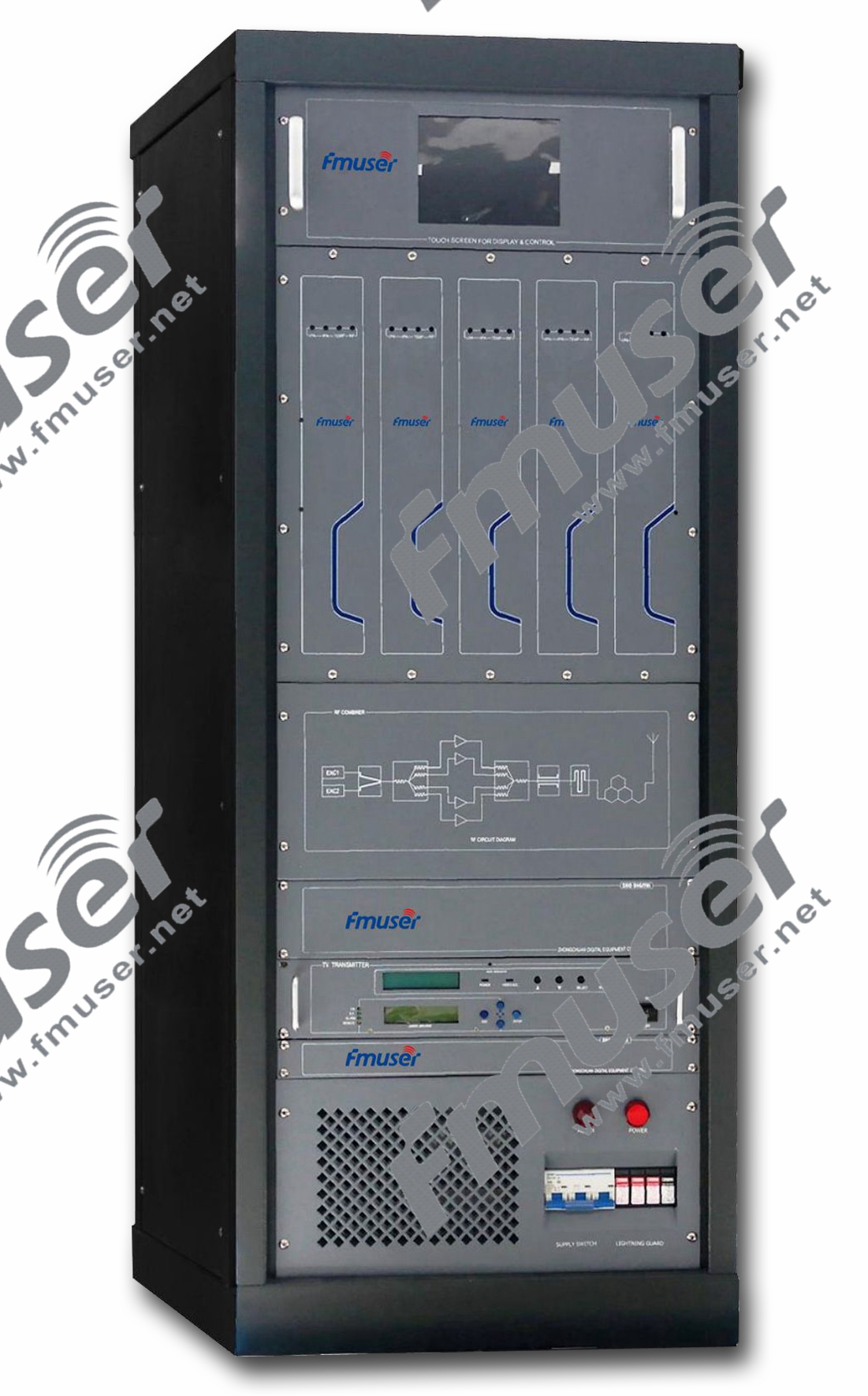
ਪ੍ਰਸਾਰਣ ਟ੍ਰਾਂਸਮੀਟਰ
ਬ੍ਰੌਡਕਾਸਟਿੰਗ ਟ੍ਰਾਂਸਮੀਟਰ ਰੇਡੀਓ ਅਤੇ ਟੈਲੀਵਿਜ਼ਨ ਸਟੇਸ਼ਨਾਂ ਦਾ ਦਿਲ ਹੁੰਦੇ ਹਨ, ਜੋ ਕਿ ਆਡੀਓ ਅਤੇ ਵੀਡੀਓ ਸਿਗਨਲਾਂ ਨੂੰ ਵਿਸ਼ਾਲ ਦਰਸ਼ਕਾਂ ਤੱਕ ਪਹੁੰਚਾਉਣ ਲਈ ਜ਼ਿੰਮੇਵਾਰ ਹੁੰਦੇ ਹਨ। ਉਹ ਘਰਾਂ ਅਤੇ ਵਾਹਨਾਂ ਵਿੱਚ ਰੇਡੀਓ ਅਤੇ ਟੈਲੀਵਿਜ਼ਨਾਂ ਨੂੰ ਏਅਰਵੇਵਜ਼ ਉੱਤੇ ਉੱਚ-ਗੁਣਵੱਤਾ ਵਾਲੀ ਸਮੱਗਰੀ ਦੀ ਡਿਲਿਵਰੀ ਨੂੰ ਯਕੀਨੀ ਬਣਾਉਂਦੇ ਹਨ। ਬ੍ਰੌਡਕਾਸਟਿੰਗ ਟ੍ਰਾਂਸਮੀਟਰ ਵੱਖ-ਵੱਖ ਕਿਸਮਾਂ ਨੂੰ ਸ਼ਾਮਲ ਕਰਦੇ ਹਨ, ਜਿਸ ਵਿੱਚ FM ਬ੍ਰੌਡਕਾਸਟ ਟ੍ਰਾਂਸਮੀਟਰ, AM ਟ੍ਰਾਂਸਮੀਟਰ, ਅਤੇ ਟੀਵੀ ਪ੍ਰਸਾਰਣ ਟ੍ਰਾਂਸਮੀਟਰ ਸ਼ਾਮਲ ਹਨ। ਆਉ ਇਹਨਾਂ ਕਿਸਮਾਂ ਅਤੇ ਪ੍ਰਸਾਰਣ ਉਦਯੋਗ ਵਿੱਚ ਉਹਨਾਂ ਦੀ ਮਹੱਤਤਾ ਦੀ ਪੜਚੋਲ ਕਰੀਏ।
- FM ਬ੍ਰੌਡਕਾਸਟ ਟ੍ਰਾਂਸਮੀਟਰ: FM (ਫ੍ਰੀਕੁਐਂਸੀ ਮੋਡਿਊਲੇਸ਼ਨ) ਪ੍ਰਸਾਰਣ ਟ੍ਰਾਂਸਮੀਟਰ ਰੇਡੀਓ ਪ੍ਰਸਾਰਣ ਲਈ ਵਿਆਪਕ ਤੌਰ 'ਤੇ ਵਰਤੇ ਜਾਂਦੇ ਹਨ। ਉਹ ਐਫਐਮ ਬੈਂਡ ਉੱਤੇ ਆਡੀਓ ਸਿਗਨਲ ਪ੍ਰਸਾਰਿਤ ਕਰਦੇ ਹਨ, ਸੁਣਨ ਵਾਲਿਆਂ ਨੂੰ ਸਪਸ਼ਟ ਅਤੇ ਉੱਚ-ਵਫ਼ਾਦਾਰ ਆਵਾਜ਼ ਪ੍ਰਦਾਨ ਕਰਦੇ ਹਨ। ਐਫਐਮ ਟ੍ਰਾਂਸਮੀਟਰ ਆਡੀਓ ਸਿਗਨਲ ਦੇ ਨਾਲ ਕੈਰੀਅਰ ਦੀ ਬਾਰੰਬਾਰਤਾ ਨੂੰ ਮੋਡਿਊਲੇਟ ਕਰਦੇ ਹਨ, ਜਿਸ ਨਾਲ ਫ੍ਰੀਕੁਐਂਸੀ ਅਤੇ ਸਟੀਰੀਓ ਟ੍ਰਾਂਸਮਿਸ਼ਨ ਦੀ ਇੱਕ ਵਿਸ਼ਾਲ ਸ਼੍ਰੇਣੀ ਦੀ ਆਗਿਆ ਦਿੱਤੀ ਜਾਂਦੀ ਹੈ। FM ਪ੍ਰਸਾਰਣ ਇਸਦੀ ਉੱਚੀ ਆਵਾਜ਼ ਦੀ ਗੁਣਵੱਤਾ ਲਈ ਪ੍ਰਸਿੱਧ ਹੈ, ਇਸ ਨੂੰ ਸੰਗੀਤ ਸਟੇਸ਼ਨਾਂ, ਟਾਕ ਸ਼ੋਆਂ ਅਤੇ ਹੋਰ ਰੇਡੀਓ ਪ੍ਰੋਗਰਾਮਿੰਗ ਲਈ ਢੁਕਵਾਂ ਬਣਾਉਂਦਾ ਹੈ। >> ਹੋਰ ਜਾਣੋ
- AM ਟ੍ਰਾਂਸਮੀਟਰ: AM (ਐਂਪਲੀਟਿਊਡ ਮੋਡੂਲੇਸ਼ਨ) ਟ੍ਰਾਂਸਮੀਟਰ AM ਰੇਡੀਓ ਪ੍ਰਸਾਰਣ ਵਿੱਚ ਮਹੱਤਵਪੂਰਣ ਭੂਮਿਕਾ ਨਿਭਾਉਂਦੇ ਹਨ। ਉਹ ਆਵਾਜ਼ ਅਤੇ ਸੰਗੀਤ ਨੂੰ ਪ੍ਰਸਾਰਿਤ ਕਰਨ ਲਈ ਆਡੀਓ ਸਿਗਨਲ ਨਾਲ ਕੈਰੀਅਰ ਬਾਰੰਬਾਰਤਾ ਦੇ ਐਪਲੀਟਿਊਡ ਨੂੰ ਮੋਡਿਊਲੇਟ ਕਰਦੇ ਹਨ। AM ਪ੍ਰਸਾਰਣ ਦਾ ਇੱਕ ਲੰਮਾ ਇਤਿਹਾਸ ਹੈ ਅਤੇ ਖ਼ਬਰਾਂ, ਟਾਕ ਸ਼ੋਅ, ਖੇਡਾਂ ਅਤੇ ਹੋਰ ਸਮੱਗਰੀ ਲਈ ਵਿਆਪਕ ਤੌਰ 'ਤੇ ਵਰਤਿਆ ਜਾਣਾ ਜਾਰੀ ਹੈ। AM ਟਰਾਂਸਮੀਟਰਾਂ ਦਾ ਇੱਕ ਵਿਆਪਕ ਕਵਰੇਜ ਖੇਤਰ ਹੁੰਦਾ ਹੈ ਪਰ ਵਾਯੂਮੰਡਲ ਦੇ ਦਖਲਅੰਦਾਜ਼ੀ ਲਈ ਵਧੇਰੇ ਸੰਵੇਦਨਸ਼ੀਲ ਹੁੰਦੇ ਹਨ, ਉਹਨਾਂ ਨੂੰ ਲੰਬੀ-ਸੀਮਾ ਦੇ ਪ੍ਰਸਾਰਣ ਅਤੇ ਰਾਤ ਦੇ ਸਮੇਂ ਸੁਣਨ ਲਈ ਢੁਕਵਾਂ ਬਣਾਉਂਦੇ ਹਨ। >> ਹੋਰ ਜਾਣੋ
- ਟੀਵੀ ਪ੍ਰਸਾਰਣ ਟ੍ਰਾਂਸਮੀਟਰ: ਟੀਵੀ ਪ੍ਰਸਾਰਣ ਟ੍ਰਾਂਸਮੀਟਰ ਟੈਲੀਵਿਜ਼ਨ ਪ੍ਰਸਾਰਣ ਦੀ ਰੀੜ੍ਹ ਦੀ ਹੱਡੀ ਬਣਦੇ ਹਨ। ਉਹ ਆਡੀਓ ਅਤੇ ਵੀਡੀਓ ਸਿਗਨਲ ਨੂੰ ਹਵਾ ਰਾਹੀਂ ਟੈਲੀਵਿਜ਼ਨਾਂ ਤੱਕ ਪ੍ਰਸਾਰਿਤ ਕਰਦੇ ਹਨ, ਜਿਸ ਨਾਲ ਦਰਸ਼ਕਾਂ ਨੂੰ ਉਨ੍ਹਾਂ ਦੇ ਮਨਪਸੰਦ ਪ੍ਰੋਗਰਾਮ ਦੇਖਣ ਦੇ ਯੋਗ ਬਣਦੇ ਹਨ। ਟੀਵੀ ਟ੍ਰਾਂਸਮੀਟਰ ਕਿਸੇ ਖਾਸ ਖੇਤਰ ਦੇ ਪ੍ਰਸਾਰਣ ਮਾਪਦੰਡਾਂ 'ਤੇ ਨਿਰਭਰ ਕਰਦੇ ਹੋਏ, ਕਈ ਮਾਡੂਲੇਸ਼ਨ ਤਕਨੀਕਾਂ ਦੀ ਵਰਤੋਂ ਕਰਦੇ ਹਨ, ਜਿਵੇਂ ਕਿ ਡਿਜੀਟਲ (ATSC) ਜਾਂ ਐਨਾਲਾਗ (NTSC)। ਟੀਵੀ ਟ੍ਰਾਂਸਮੀਟਰ ਇੱਕ ਵਿਸ਼ਾਲ ਬਾਰੰਬਾਰਤਾ ਰੇਂਜ ਨੂੰ ਕਵਰ ਕਰਦੇ ਹਨ ਅਤੇ ਲੋੜੀਂਦੇ ਕਵਰੇਜ ਖੇਤਰ ਤੱਕ ਪਹੁੰਚਣ ਲਈ ਉੱਚ ਪਾਵਰ ਲੈਵਲ ਦੀ ਲੋੜ ਹੁੰਦੀ ਹੈ। >> ਹੋਰ ਜਾਣੋ
FM, AM, ਅਤੇ TV ਪ੍ਰਸਾਰਣ ਟ੍ਰਾਂਸਮੀਟਰਾਂ ਤੋਂ ਇਲਾਵਾ, ਵਿਸ਼ੇਸ਼ ਐਪਲੀਕੇਸ਼ਨਾਂ ਲਈ ਹੋਰ ਕਿਸਮ ਦੇ ਪ੍ਰਸਾਰਣ ਟ੍ਰਾਂਸਮੀਟਰ ਮੌਜੂਦ ਹਨ। ਇਹਨਾਂ ਵਿੱਚ ਸੈਟੇਲਾਈਟਾਂ ਰਾਹੀਂ ਪ੍ਰਸਾਰਣ ਲਈ ਡਿਜੀਟਲ ਰੇਡੀਓ ਟ੍ਰਾਂਸਮੀਟਰ (ਉਦਾਹਰਨ ਲਈ, DAB, HD ਰੇਡੀਓ), ਸ਼ਾਰਟਵੇਵ ਟ੍ਰਾਂਸਮੀਟਰ, ਅਤੇ ਸੈਟੇਲਾਈਟ ਅੱਪਲਿੰਕ ਟ੍ਰਾਂਸਮੀਟਰ ਸ਼ਾਮਲ ਹਨ। ਇਹ ਟ੍ਰਾਂਸਮੀਟਰ ਵਿਭਿੰਨ ਦਰਸ਼ਕਾਂ ਨੂੰ ਸਮੱਗਰੀ ਪ੍ਰਦਾਨ ਕਰਨ ਲਈ ਵਿਸਤ੍ਰਿਤ ਵਿਕਲਪਾਂ ਦੀ ਪੇਸ਼ਕਸ਼ ਕਰਦੇ ਹੋਏ, ਖਾਸ ਪ੍ਰਸਾਰਣ ਲੋੜਾਂ ਅਤੇ ਤਕਨਾਲੋਜੀਆਂ ਨੂੰ ਪੂਰਾ ਕਰਦੇ ਹਨ।
ਪ੍ਰਸਾਰਣ ਟ੍ਰਾਂਸਮੀਟਰ ਧਿਆਨ ਨਾਲ ਤਿਆਰ ਕੀਤੇ ਗਏ ਹਨ, ਅਨੁਕੂਲ ਸਿਗਨਲ ਗੁਣਵੱਤਾ, ਕਵਰੇਜ, ਅਤੇ ਰੈਗੂਲੇਟਰੀ ਮਾਪਦੰਡਾਂ ਦੀ ਪਾਲਣਾ ਨੂੰ ਯਕੀਨੀ ਬਣਾਉਣ ਲਈ ਉੱਨਤ ਤਕਨਾਲੋਜੀਆਂ ਨੂੰ ਸ਼ਾਮਲ ਕਰਦੇ ਹੋਏ। ਉਹਨਾਂ ਨੂੰ ਆਮ ਤੌਰ 'ਤੇ ਰੇਡੀਓ ਜਾਂ ਟੀਵੀ ਐਂਟੀਨਾ ਦੁਆਰਾ ਰਿਸੈਪਸ਼ਨ ਲਈ ਸਪੇਸ ਵਿੱਚ ਸਿਗਨਲਾਂ ਨੂੰ ਰੇਡੀਏਟ ਕਰਨ ਲਈ ਐਂਟੀਨਾ ਨਾਲ ਜੋੜਿਆ ਜਾਂਦਾ ਹੈ।
ਐਫਐਮ ਰੇਡੀਓ ਟ੍ਰਾਂਸਮੀਟਰ
ਐਫਐਮ ਰੇਡੀਓ ਟ੍ਰਾਂਸਮੀਟਰ ਰੇਡੀਓ ਸਟੂਡੀਓ ਤੋਂ ਆਵਾਜ਼ ਨੂੰ ਕੈਪਚਰ ਕਰਨ ਅਤੇ ਇੱਕ ਐਫਐਮ ਐਂਟੀਨਾ ਦੁਆਰਾ ਨਿਰਧਾਰਤ ਰੇਡੀਓ ਪ੍ਰਾਪਤ ਕਰਨ ਵਾਲੇ ਖੇਤਰ ਵਿੱਚ ਪ੍ਰਸਾਰਣ ਵਿੱਚ ਇੱਕ ਮਹੱਤਵਪੂਰਣ ਭੂਮਿਕਾ ਅਦਾ ਕਰਦਾ ਹੈ। ਇਹ ਟ੍ਰਾਂਸਮੀਟਰ ਜਾਂ ਤਾਂ ਇੱਕ ਵੱਖਰਾ ਇਲੈਕਟ੍ਰਾਨਿਕ ਡਿਵਾਈਸ ਜਾਂ ਕਿਸੇ ਹੋਰ ਇਲੈਕਟ੍ਰਾਨਿਕ ਡਿਵਾਈਸ ਦੇ ਅੰਦਰ ਇੱਕ ਸਰਕਟ ਹੋ ਸਕਦਾ ਹੈ। ਜਦੋਂ ਟ੍ਰਾਂਸਮੀਟਰ ਅਤੇ ਰਿਸੀਵਰ ਨੂੰ ਇੱਕ ਯੂਨਿਟ ਵਿੱਚ ਜੋੜਿਆ ਜਾਂਦਾ ਹੈ, ਤਾਂ ਉਹਨਾਂ ਨੂੰ ਟ੍ਰਾਂਸਸੀਵਰ ਕਿਹਾ ਜਾਂਦਾ ਹੈ। ਤਕਨੀਕੀ ਦਸਤਾਵੇਜ਼ਾਂ ਵਿੱਚ, "ਟ੍ਰਾਂਸਮੀਟਰ" ਸ਼ਬਦ ਨੂੰ ਅਕਸਰ "XMTR" ਜਾਂ "TX" ਕਿਹਾ ਜਾਂਦਾ ਹੈ। ਟ੍ਰਾਂਸਮੀਟਰਾਂ ਦਾ ਮੁੱਖ ਉਦੇਸ਼ ਇੱਕ ਖਾਸ ਦੂਰੀ 'ਤੇ ਰੇਡੀਓ ਜਾਣਕਾਰੀ ਸੰਚਾਰ ਦੀ ਸਹੂਲਤ ਦੇਣਾ ਹੈ।
FM ਰੇਡੀਓ ਟ੍ਰਾਂਸਮੀਟਰ ਕਿਵੇਂ ਕੰਮ ਕਰਦਾ ਹੈ?
ਜਾਣਕਾਰੀ ਪ੍ਰਸਾਰਿਤ ਕਰਨ ਲਈ, ਟ੍ਰਾਂਸਮੀਟਰ ਇਲੈਕਟ੍ਰਾਨਿਕ ਸਿਗਨਲ ਪ੍ਰਾਪਤ ਕਰਦਾ ਹੈ, ਜਿਵੇਂ ਕਿ ਮਾਈਕ੍ਰੋਫੋਨ ਤੋਂ ਆਡੀਓ (ਧੁਨੀ) ਸਿਗਨਲ, ਕੈਮਰੇ ਤੋਂ ਵੀਡੀਓ (ਟੀਵੀ) ਸਿਗਨਲ, ਜਾਂ ਵਾਇਰਲੈੱਸ ਨੈਟਵਰਕ ਡਿਵਾਈਸਾਂ ਦੇ ਮਾਮਲੇ ਵਿੱਚ ਕੰਪਿਊਟਰ ਤੋਂ ਡਿਜੀਟਲ ਸਿਗਨਲ। ਟ੍ਰਾਂਸਮੀਟਰ ਰੇਡੀਓ ਤਰੰਗਾਂ ਪੈਦਾ ਕਰਨ ਲਈ ਇੱਕ ਰੇਡੀਓ ਫ੍ਰੀਕੁਐਂਸੀ ਸਿਗਨਲ ਦੇ ਨਾਲ ਜਾਣਕਾਰੀ ਸਿਗਨਲ ਨੂੰ ਜੋੜਦਾ ਹੈ, ਜਿਸਨੂੰ ਕੈਰੀਅਰ ਸਿਗਨਲ ਕਿਹਾ ਜਾਂਦਾ ਹੈ। ਇਸ ਪ੍ਰਕਿਰਿਆ ਨੂੰ ਮੋਡੂਲੇਸ਼ਨ ਕਿਹਾ ਜਾਂਦਾ ਹੈ। ਵੱਖ-ਵੱਖ ਕਿਸਮਾਂ ਦੇ ਟ੍ਰਾਂਸਮੀਟਰ ਕੈਰੀਅਰ ਸਿਗਨਲ ਵਿੱਚ ਜਾਣਕਾਰੀ ਜੋੜਨ ਲਈ ਵੱਖ-ਵੱਖ ਤਰੀਕਿਆਂ ਦੀ ਵਰਤੋਂ ਕਰਦੇ ਹਨ। ਉਦਾਹਰਨ ਲਈ, AM ਟ੍ਰਾਂਸਮੀਟਰਾਂ ਵਿੱਚ, ਜਾਣਕਾਰੀ ਨੂੰ ਐਪਲੀਟਿਊਡ ਨੂੰ ਬਦਲ ਕੇ ਜੋੜਿਆ ਜਾਂਦਾ ਹੈ, ਜਦੋਂ ਕਿ FM ਟ੍ਰਾਂਸਮੀਟਰਾਂ ਵਿੱਚ, ਇਹ ਬਾਰੰਬਾਰਤਾ ਨੂੰ ਥੋੜ੍ਹਾ ਬਦਲ ਕੇ ਪ੍ਰਾਪਤ ਕੀਤਾ ਜਾਂਦਾ ਹੈ। ਇੱਥੇ ਕਈ ਹੋਰ ਮੋਡੂਲੇਸ਼ਨ ਤਕਨੀਕਾਂ ਵੀ ਵਰਤੀਆਂ ਜਾਂਦੀਆਂ ਹਨ।
ਟਰਾਂਸਮੀਟਰ ਦੁਆਰਾ ਤਿਆਰ ਕੀਤੇ ਗਏ ਰੇਡੀਓ ਸਿਗਨਲ ਨੂੰ ਫਿਰ ਇੱਕ ਐਂਟੀਨਾ ਵੱਲ ਨਿਰਦੇਸ਼ਿਤ ਕੀਤਾ ਜਾਂਦਾ ਹੈ, ਜੋ ਰੇਡੀਓ ਤਰੰਗਾਂ ਦੇ ਰੂਪ ਵਿੱਚ ਊਰਜਾ ਨੂੰ ਰੇਡੀਏਟ ਕਰਦਾ ਹੈ। ਐਂਟੀਨਾ ਨੂੰ ਜਾਂ ਤਾਂ ਟ੍ਰਾਂਸਮੀਟਰ ਦੇ ਹਾਊਸਿੰਗ ਦੇ ਅੰਦਰ ਬੰਦ ਕੀਤਾ ਜਾ ਸਕਦਾ ਹੈ ਜਾਂ ਬਾਹਰੀ ਤੌਰ 'ਤੇ ਕਨੈਕਟ ਕੀਤਾ ਜਾ ਸਕਦਾ ਹੈ, ਜਿਵੇਂ ਕਿ ਮੋਬਾਈਲ ਫੋਨਾਂ, ਵਾਕੀ-ਟਾਕੀਜ਼, ਅਤੇ ਗੈਰੇਜ ਦੇ ਦਰਵਾਜ਼ੇ ਖੋਲ੍ਹਣ ਵਾਲੇ ਪੋਰਟੇਬਲ ਡਿਵਾਈਸਾਂ ਵਿੱਚ ਦੇਖਿਆ ਜਾਂਦਾ ਹੈ। ਵਧੇਰੇ ਸ਼ਕਤੀਸ਼ਾਲੀ ਟ੍ਰਾਂਸਮੀਟਰਾਂ ਵਿੱਚ, ਐਂਟੀਨਾ ਅਕਸਰ ਇੱਕ ਇਮਾਰਤ ਜਾਂ ਇੱਕ ਵੱਖਰੇ ਟਾਵਰ ਦੇ ਸਿਖਰ 'ਤੇ ਸਥਿਤ ਹੁੰਦਾ ਹੈ, ਇੱਕ ਫੀਡਰ, ਜਾਂ ਟ੍ਰਾਂਸਮਿਸ਼ਨ ਲਾਈਨ ਰਾਹੀਂ ਟ੍ਰਾਂਸਮੀਟਰ ਨਾਲ ਜੁੜਿਆ ਹੁੰਦਾ ਹੈ।
FM ਟ੍ਰਾਂਸਮੀਟਰਾਂ ਨੂੰ ਉਹਨਾਂ ਦੀਆਂ ਆਉਟਪੁੱਟ ਪਾਵਰ ਸਮਰੱਥਾਵਾਂ ਦੇ ਅਧਾਰ ਤੇ ਘੱਟ-ਪਾਵਰ, ਮੱਧਮ-ਪਾਵਰ, ਅਤੇ ਉੱਚ-ਪਾਵਰ ਵਿੱਚ ਸ਼੍ਰੇਣੀਬੱਧ ਕੀਤਾ ਗਿਆ ਹੈ। ਹਰੇਕ ਸ਼੍ਰੇਣੀ ਵੱਖ-ਵੱਖ ਉਦੇਸ਼ਾਂ ਅਤੇ ਐਪਲੀਕੇਸ਼ਨਾਂ ਨੂੰ ਪੂਰਾ ਕਰਦੀ ਹੈ। ਇੱਥੇ ਇਹਨਾਂ FM ਟ੍ਰਾਂਸਮੀਟਰ ਸ਼੍ਰੇਣੀਆਂ ਦੀ ਇੱਕ ਸੰਖੇਪ ਜਾਣਕਾਰੀ ਹੈ:
- ਘੱਟ ਪਾਵਰ ਐਫਐਮ ਟ੍ਰਾਂਸਮੀਟਰ: ਘੱਟ-ਪਾਵਰ ਐਫਐਮ ਟ੍ਰਾਂਸਮੀਟਰਾਂ ਵਿੱਚ ਆਮ ਤੌਰ 'ਤੇ ਕੁਝ ਵਾਟਸ ਤੋਂ ਲੈ ਕੇ ਦਸਾਂ ਵਾਟਸ ਦੀ ਆਉਟਪੁੱਟ ਪਾਵਰ ਰੇਂਜ ਹੁੰਦੀ ਹੈ। ਉਹ ਆਮ ਤੌਰ 'ਤੇ ਕਮਿਊਨਿਟੀ ਰੇਡੀਓ ਸਟੇਸ਼ਨਾਂ, ਛੋਟੇ ਪੈਮਾਨੇ ਦੇ ਪ੍ਰਸਾਰਣ, ਸਥਾਨਕ ਸਮਾਗਮਾਂ, ਅਤੇ ਵਿਸ਼ੇਸ਼ ਐਪਲੀਕੇਸ਼ਨਾਂ ਵਿੱਚ ਵਰਤੇ ਜਾਂਦੇ ਹਨ। ਇਹ ਟ੍ਰਾਂਸਮੀਟਰ ਆਕਾਰ ਵਿੱਚ ਸੰਖੇਪ ਹਨ ਅਤੇ ਸੀਮਤ ਕਵਰੇਜ ਖੇਤਰਾਂ ਲਈ ਲਾਗਤ-ਪ੍ਰਭਾਵਸ਼ਾਲੀ ਹੱਲ ਪੇਸ਼ ਕਰਦੇ ਹਨ। ਘੱਟ-ਪਾਵਰ ਐਫਐਮ ਟ੍ਰਾਂਸਮੀਟਰ ਛੋਟੀ-ਸੀਮਾ ਦੇ ਪ੍ਰਸਾਰਣ ਲਈ ਢੁਕਵੇਂ ਹਨ, ਜਿਵੇਂ ਕਿ ਗੁਆਂਢ ਜਾਂ ਛੋਟੇ ਕੈਂਪਸ ਦੇ ਅੰਦਰ।
- ਮੀਡੀਅਮ ਪਾਵਰ ਐਫਐਮ ਟ੍ਰਾਂਸਮੀਟਰ: ਮੱਧਮ-ਪਾਵਰ ਐਫਐਮ ਟ੍ਰਾਂਸਮੀਟਰਾਂ ਵਿੱਚ ਉੱਚ ਆਉਟਪੁੱਟ ਪਾਵਰ ਸਮਰੱਥਾ ਹੁੰਦੀ ਹੈ, ਕਈ ਦਸਾਂ ਤੋਂ ਲੈ ਕੇ ਸੈਂਕੜੇ ਵਾਟਸ ਤੱਕ। ਉਹ ਖੇਤਰੀ ਰੇਡੀਓ ਸਟੇਸ਼ਨਾਂ ਅਤੇ ਕਵਰੇਜ ਖੇਤਰਾਂ ਲਈ ਤਿਆਰ ਕੀਤੇ ਗਏ ਹਨ ਜਿਨ੍ਹਾਂ ਨੂੰ ਮੱਧਮ ਪ੍ਰਸਾਰਣ ਰੇਂਜ ਦੀ ਲੋੜ ਹੁੰਦੀ ਹੈ। ਮੱਧਮ-ਪਾਵਰ ਟਰਾਂਸਮੀਟਰ ਘੱਟ-ਪਾਵਰ ਟ੍ਰਾਂਸਮੀਟਰਾਂ ਦੇ ਮੁਕਾਬਲੇ ਬਿਹਤਰ ਸਿਗਨਲ ਤਾਕਤ ਅਤੇ ਕਵਰੇਜ ਦੀ ਪੇਸ਼ਕਸ਼ ਕਰਦੇ ਹਨ, ਉਹਨਾਂ ਨੂੰ ਵਿਸ਼ਾਲ ਭੂਗੋਲਿਕ ਖੇਤਰਾਂ ਲਈ ਢੁਕਵਾਂ ਬਣਾਉਂਦੇ ਹਨ। ਉਹ ਆਮ ਤੌਰ 'ਤੇ ਖੇਤਰੀ ਪ੍ਰਸਾਰਕਾਂ, ਵਿਦਿਅਕ ਸੰਸਥਾਵਾਂ ਅਤੇ ਛੋਟੇ ਤੋਂ ਮੱਧ ਆਕਾਰ ਦੇ ਰੇਡੀਓ ਸਟੇਸ਼ਨਾਂ ਦੁਆਰਾ ਵਰਤੇ ਜਾਂਦੇ ਹਨ।
- ਹਾਈ ਪਾਵਰ ਐਫਐਮ ਟ੍ਰਾਂਸਮੀਟਰ: ਉੱਚ-ਪਾਵਰ ਐਫਐਮ ਟ੍ਰਾਂਸਮੀਟਰ ਵਪਾਰਕ ਪ੍ਰਸਾਰਣ ਲਈ ਬਣਾਏ ਗਏ ਹਨ ਅਤੇ ਵੱਡੀ ਗਿਣਤੀ ਵਿੱਚ ਸਰੋਤਿਆਂ ਦੇ ਨਾਲ ਵੱਡੇ ਕਵਰੇਜ ਖੇਤਰਾਂ ਦੀ ਸੇਵਾ ਕਰਦੇ ਹਨ। ਉਹਨਾਂ ਕੋਲ ਬਹੁਤ ਜ਼ਿਆਦਾ ਆਉਟਪੁੱਟ ਪਾਵਰ ਹੈ, ਕਈ ਸੌ ਵਾਟਸ ਤੋਂ ਕਿਲੋਵਾਟ ਜਾਂ ਮਲਟੀ-ਕਿਲੋਵਾਟ ਤੱਕ। ਉੱਚ-ਪਾਵਰ ਟ੍ਰਾਂਸਮੀਟਰਾਂ ਦੀ ਵਰਤੋਂ ਵੱਡੇ ਰੇਡੀਓ ਸਟੇਸ਼ਨਾਂ ਅਤੇ ਪ੍ਰਸਾਰਣ ਨੈੱਟਵਰਕਾਂ ਦੁਆਰਾ ਵਿਆਪਕ ਭੂਗੋਲਿਕ ਖੇਤਰਾਂ ਤੱਕ ਪਹੁੰਚਣ ਲਈ ਕੀਤੀ ਜਾਂਦੀ ਹੈ। ਇਹਨਾਂ ਟ੍ਰਾਂਸਮੀਟਰਾਂ ਨੂੰ ਵਪਾਰਕ ਪ੍ਰਸਾਰਣ ਲਈ ਵਧੇਰੇ ਵਧੀਆ ਬੁਨਿਆਦੀ ਢਾਂਚੇ, ਵੱਡੇ ਐਂਟੀਨਾ ਪ੍ਰਣਾਲੀਆਂ ਅਤੇ ਰੈਗੂਲੇਟਰੀ ਲੋੜਾਂ ਦੀ ਪਾਲਣਾ ਦੀ ਲੋੜ ਹੁੰਦੀ ਹੈ।
ਇੱਕ FM ਟ੍ਰਾਂਸਮੀਟਰ ਦੀ ਕਵਰੇਜ ਰੇਂਜ ਅਤੇ ਦਰਸ਼ਕਾਂ ਦੀ ਪਹੁੰਚ ਨੂੰ ਨਿਰਧਾਰਤ ਕਰਨ ਵਿੱਚ ਆਉਟਪੁੱਟ ਪਾਵਰ ਇੱਕ ਮਹੱਤਵਪੂਰਨ ਕਾਰਕ ਹੈ। FM ਟ੍ਰਾਂਸਮੀਟਰਾਂ ਦਾ ਆਕਾਰ, ਕੀਮਤ, ਅਤੇ ਵਿਸ਼ੇਸ਼ਤਾਵਾਂ ਖਾਸ ਐਪਲੀਕੇਸ਼ਨ ਦੀਆਂ ਲੋੜੀਂਦੀਆਂ ਵਿਸ਼ੇਸ਼ਤਾਵਾਂ ਅਤੇ ਲੋੜਾਂ 'ਤੇ ਨਿਰਭਰ ਕਰਦੇ ਹੋਏ, ਹਰੇਕ ਪਾਵਰ ਸ਼੍ਰੇਣੀ ਦੇ ਅੰਦਰ ਵੱਖ-ਵੱਖ ਹੁੰਦੀਆਂ ਹਨ।
ਇੱਕ FM ਟ੍ਰਾਂਸਮੀਟਰ ਦੀ ਚੋਣ ਕਰਦੇ ਸਮੇਂ, ਪਾਵਰ ਸ਼੍ਰੇਣੀ ਨੂੰ ਧਿਆਨ ਵਿੱਚ ਰੱਖਣਾ ਜ਼ਰੂਰੀ ਹੈ ਜੋ ਇੱਛਤ ਕਵਰੇਜ ਖੇਤਰ, ਜਿਵੇਂ ਕਿ ਇੱਕ ਛੋਟਾ ਆਂਢ-ਗੁਆਂਢ ਜਾਂ ਇੱਕ ਪੂਰਾ ਖੇਤਰ, ਨਾਲ ਸਭ ਤੋਂ ਵਧੀਆ ਇਕਸਾਰ ਹੈ। ਇਸ ਤੋਂ ਇਲਾਵਾ, ਰੈਗੂਲੇਟਰੀ ਪਾਬੰਦੀਆਂ, ਬਜਟ ਦੀਆਂ ਰੁਕਾਵਟਾਂ, ਅਤੇ ਲੋੜੀਂਦੀ ਆਡੀਓ ਗੁਣਵੱਤਾ ਵਰਗੇ ਕਾਰਕਾਂ ਨੂੰ ਧਿਆਨ ਵਿੱਚ ਰੱਖਿਆ ਜਾਣਾ ਚਾਹੀਦਾ ਹੈ। ਉਦਯੋਗ ਦੇ ਪੇਸ਼ੇਵਰਾਂ ਨਾਲ ਸਲਾਹ-ਮਸ਼ਵਰਾ ਕਰਨਾ ਅਤੇ ਸਥਾਨਕ ਪ੍ਰਸਾਰਣ ਨਿਯਮਾਂ ਦੀ ਪਾਲਣਾ ਕਰਨਾ ਕਿਸੇ ਖਾਸ ਪ੍ਰਸਾਰਣ ਐਪਲੀਕੇਸ਼ਨ ਲਈ ਸਭ ਤੋਂ ਢੁਕਵਾਂ FM ਟ੍ਰਾਂਸਮੀਟਰ ਚੁਣਨ ਵਿੱਚ ਮਦਦ ਕਰੇਗਾ।
ਤੁਹਾਡੇ ਲਈ ਸਿਫ਼ਾਰਿਸ਼ ਕੀਤੇ FM ਟ੍ਰਾਂਸਮੀਟਰ
 |
 |
 |
| ਘੱਟ ਪਾਵਰ ਐਫਐਮ ਟ੍ਰਾਂਸਮੀਟਰ 100W ਤੱਕ | 1000W ਤੱਕ ਮੱਧਮ ਪਾਵਰ ਐਫਐਮ ਟ੍ਰਾਂਸਮੀਟਰ | 10kW ਤੱਕ ਹਾਈ ਪਾਵਰ ਐਫਐਮ ਟ੍ਰਾਂਸਮੀਟਰ |
FM ਬ੍ਰੌਡਕਾਸਟ ਟ੍ਰਾਂਸਮੀਟਰਾਂ ਵਿੱਚ ਪਾਰਟਸ ਅਤੇ ਰਿਪਲੇਸਮੈਂਟ ਪਾਰਟਸ ਨੂੰ ਫਿਕਸ ਕਰਨਾ
ਜਦੋਂ ਇੱਕ FM ਪ੍ਰਸਾਰਣ ਟ੍ਰਾਂਸਮੀਟਰ ਟੁੱਟ ਜਾਂਦਾ ਹੈ ਜਾਂ ਖਰਾਬ ਹੋ ਜਾਂਦਾ ਹੈ, ਤਾਂ ਇਸਨੂੰ ਅਕਸਰ ਕੁਝ ਹਿੱਸਿਆਂ ਨੂੰ ਠੀਕ ਕਰਨ ਜਾਂ ਬਦਲਣ ਦੀ ਲੋੜ ਹੁੰਦੀ ਹੈ। ਐਫਐਮ ਪ੍ਰਸਾਰਣ ਟ੍ਰਾਂਸਮੀਟਰਾਂ ਦੇ ਸੰਦਰਭ ਵਿੱਚ, "ਫਿਕਸਿੰਗ ਪਾਰਟਸ" ਅਤੇ "ਰਿਪਲੇਸਮੈਂਟ ਪਾਰਟਸ" ਆਮ ਤੌਰ 'ਤੇ ਇੱਕੋ ਚੀਜ਼ ਦਾ ਹਵਾਲਾ ਦਿੰਦੇ ਹਨ, ਜੋ ਕਿ ਉਹ ਹਿੱਸੇ ਜਾਂ ਮੋਡੀਊਲ ਹਨ ਜੋ ਟ੍ਰਾਂਸਮੀਟਰ ਦੇ ਅੰਦਰ ਨੁਕਸਦਾਰ ਹਿੱਸਿਆਂ ਦੀ ਮੁਰੰਮਤ ਜਾਂ ਬਦਲਣ ਲਈ ਵਰਤੇ ਜਾਂਦੇ ਹਨ।
ਫਿਕਸਿੰਗ ਪਾਰਟਸ
ਫਿਕਸਿੰਗ ਪਾਰਟਸ ਇੱਕ FM ਪ੍ਰਸਾਰਣ ਟ੍ਰਾਂਸਮੀਟਰ ਵਿੱਚ ਖਾਸ ਮੁੱਦਿਆਂ ਜਾਂ ਨੁਕਸ ਨੂੰ ਦੂਰ ਕਰਨ ਲਈ ਵਰਤੇ ਜਾਂਦੇ ਹਿੱਸੇ ਹਨ। ਉਹ ਆਮ ਤੌਰ 'ਤੇ ਉਦੋਂ ਕੰਮ ਕਰਦੇ ਹਨ ਜਦੋਂ ਅਸਲ ਹਿੱਸੇ ਦੀ ਮੁਰੰਮਤ ਕੀਤੀ ਜਾ ਸਕਦੀ ਹੈ, ਨਾ ਕਿ ਪੂਰੀ ਤਰ੍ਹਾਂ ਨਾਲ ਬਦਲੀ ਜਾਣ ਦੀ। ਫਿਕਸਿੰਗ ਭਾਗਾਂ ਵਿੱਚ ਆਈਟਮਾਂ ਸ਼ਾਮਲ ਹੋ ਸਕਦੀਆਂ ਹਨ ਜਿਵੇਂ ਕਿ:
- ਸਰਕਟ ਬੋਰਡ ਦੇ ਹਿੱਸੇ: ਇਹਨਾਂ ਵਿੱਚ ਕੈਪਸੀਟਰ, ਰੋਧਕ, ਟਰਾਂਜ਼ਿਸਟਰ, ਏਕੀਕ੍ਰਿਤ ਸਰਕਟਾਂ (ICs), ਡਾਇਡਸ, ਅਤੇ ਹੋਰ ਇਲੈਕਟ੍ਰਾਨਿਕ ਹਿੱਸੇ ਸ਼ਾਮਲ ਹੋ ਸਕਦੇ ਹਨ। ਜਦੋਂ ਇਹਨਾਂ ਵਿੱਚੋਂ ਕੋਈ ਵੀ ਭਾਗ ਫੇਲ ਹੋ ਜਾਂਦਾ ਹੈ ਜਾਂ ਖਰਾਬ ਹੋ ਜਾਂਦਾ ਹੈ, ਤਾਂ ਉਹਨਾਂ ਨੂੰ ਵੱਖਰੇ ਤੌਰ 'ਤੇ ਬਦਲਿਆ ਜਾ ਸਕਦਾ ਹੈ, ਪੂਰੇ ਸਰਕਟ ਬੋਰਡ ਨੂੰ ਬਦਲਣ ਦੇ ਮੁਕਾਬਲੇ ਸਮੇਂ ਅਤੇ ਲਾਗਤ ਦੀ ਬਚਤ ਹੁੰਦੀ ਹੈ।
- ਕਨੈਕਟਰਸ: ਕਨੈਕਟਰ ਟ੍ਰਾਂਸਮੀਟਰ ਪ੍ਰਣਾਲੀਆਂ ਵਿੱਚ ਅਸਫਲਤਾ ਦੇ ਆਮ ਬਿੰਦੂ ਹਨ। ਉਹ ਵੱਖ-ਵੱਖ ਹਿੱਸਿਆਂ ਅਤੇ ਕੇਬਲਾਂ ਵਿਚਕਾਰ ਬਿਜਲੀ ਕੁਨੈਕਸ਼ਨਾਂ ਦੀ ਸਹੂਲਤ ਦਿੰਦੇ ਹਨ। ਨੁਕਸਦਾਰ ਕਨੈਕਟਰ ਸਿਗਨਲ ਦਾ ਨੁਕਸਾਨ, ਰੁਕ-ਰੁਕ ਕੇ ਕਨੈਕਸ਼ਨ, ਜਾਂ ਹੋਰ ਸਮੱਸਿਆਵਾਂ ਦਾ ਕਾਰਨ ਬਣ ਸਕਦੇ ਹਨ। ਇਹਨਾਂ ਕਨੈਕਟਰਾਂ ਨੂੰ ਬਦਲਣ ਨਾਲ ਅਕਸਰ ਸਮੱਸਿਆ ਹੱਲ ਹੋ ਸਕਦੀ ਹੈ।
- ਪਾਵਰ ਸਪਲਾਈ ਦੇ ਹਿੱਸੇ: ਟ੍ਰਾਂਸਮੀਟਰ ਸਥਿਰ ਅਤੇ ਭਰੋਸੇਮੰਦ ਪਾਵਰ ਸਰੋਤਾਂ 'ਤੇ ਨਿਰਭਰ ਕਰਦੇ ਹਨ। ਪਾਵਰ ਸਪਲਾਈ ਕੰਪੋਨੈਂਟਸ ਨਾਲ ਸਬੰਧਤ ਹਿੱਸਿਆਂ ਨੂੰ ਫਿਕਸ ਕਰਨ ਵਿੱਚ ਰੈਕਟੀਫਾਇਰ, ਵੋਲਟੇਜ ਰੈਗੂਲੇਟਰ, ਫਿਊਜ਼ ਅਤੇ ਟ੍ਰਾਂਸਫਾਰਮਰ ਸ਼ਾਮਲ ਹੋ ਸਕਦੇ ਹਨ। ਨੁਕਸਦਾਰ ਪਾਵਰ ਸਪਲਾਈ ਕੰਪੋਨੈਂਟਸ ਨੂੰ ਬਦਲਣ ਨਾਲ ਟ੍ਰਾਂਸਮੀਟਰ ਦੀ ਸਹੀ ਕਾਰਜਕੁਸ਼ਲਤਾ ਨੂੰ ਬਹਾਲ ਕੀਤਾ ਜਾ ਸਕਦਾ ਹੈ।
ਤੁਹਾਡੇ ਲਈ ਸਿਫ਼ਾਰਿਸ਼ ਕੀਤੇ ਹਾਈ ਪਾਵਰ ਆਰਐਫ ਟਰਾਂਜ਼ਿਸਟਰ
 |
 |
 |
 |
| 150W MRFE6VP5150N | 300W MRFE6VP6300H | 600W MRFE6VP5600H | 1000W BLF188XR |
ਬਦਲਣ ਵਾਲੇ ਹਿੱਸੇ
ਦੂਜੇ ਪਾਸੇ, ਬਦਲਣ ਵਾਲੇ ਹਿੱਸੇ ਵਰਤੇ ਜਾਂਦੇ ਹਨ ਜਦੋਂ ਨੁਕਸਦਾਰ ਹਿੱਸੇ ਨੂੰ ਠੀਕ ਕਰਨਾ ਸੰਭਵ ਜਾਂ ਆਰਥਿਕ ਤੌਰ 'ਤੇ ਵਿਵਹਾਰਕ ਨਹੀਂ ਹੁੰਦਾ ਹੈ। ਅਜਿਹੇ ਮਾਮਲਿਆਂ ਵਿੱਚ, ਪੂਰੇ ਹਿੱਸੇ ਨੂੰ ਇੱਕ ਨਵੇਂ ਨਾਲ ਬਦਲਿਆ ਜਾਂਦਾ ਹੈ. ਬਦਲਣ ਵਾਲੇ ਹਿੱਸੇ ਸ਼ਾਮਲ ਹੋ ਸਕਦੇ ਹਨ:
- ਪਾਵਰ ਐਂਪਲੀਫਾਇਰ: ਇਹ ਐਫਐਮ ਪ੍ਰਸਾਰਣ ਟ੍ਰਾਂਸਮੀਟਰਾਂ ਵਿੱਚ ਮਹੱਤਵਪੂਰਨ ਭਾਗ ਹਨ, ਜੋ ਸਿਗਨਲ ਨੂੰ ਲੋੜੀਂਦੇ ਪਾਵਰ ਪੱਧਰ ਤੱਕ ਵਧਾਉਣ ਲਈ ਜ਼ਿੰਮੇਵਾਰ ਹਨ। ਜੇਕਰ ਪਾਵਰ ਐਂਪਲੀਫਾਇਰ ਫੇਲ ਹੋ ਜਾਂਦਾ ਹੈ, ਤਾਂ ਇਸਨੂੰ ਅਕਸਰ ਪੂਰੀ ਤਰ੍ਹਾਂ ਬਦਲਣ ਦੀ ਲੋੜ ਹੁੰਦੀ ਹੈ, ਕਿਉਂਕਿ ਇਸਦੀ ਮੁਰੰਮਤ ਕਰਨਾ ਅਵਿਵਹਾਰਕ ਜਾਂ ਲਾਗਤ-ਪ੍ਰਤੀਰੋਧਕ ਹੋ ਸਕਦਾ ਹੈ।
- ਬਾਰੰਬਾਰਤਾ ਸਿੰਥੇਸਾਈਜ਼ਰ: ਫ੍ਰੀਕੁਐਂਸੀ ਸਿੰਥੇਸਾਈਜ਼ਰ ਦੀ ਵਰਤੋਂ ਐਫਐਮ ਪ੍ਰਸਾਰਣ ਟ੍ਰਾਂਸਮੀਟਰਾਂ ਵਿੱਚ ਕੈਰੀਅਰ ਬਾਰੰਬਾਰਤਾ ਬਣਾਉਣ ਲਈ ਕੀਤੀ ਜਾਂਦੀ ਹੈ। ਜਦੋਂ ਇੱਕ ਬਾਰੰਬਾਰਤਾ ਸਿੰਥੇਸਾਈਜ਼ਰ ਖਰਾਬ ਹੋ ਜਾਂਦਾ ਹੈ, ਤਾਂ ਇਸਨੂੰ ਆਮ ਤੌਰ 'ਤੇ ਮੁਰੰਮਤ ਦੀ ਬਜਾਏ ਬਦਲਣ ਦੀ ਲੋੜ ਹੁੰਦੀ ਹੈ।
- ਮੋਡੂਲੇਸ਼ਨ ਜਾਂ ਆਡੀਓ ਪ੍ਰੋਸੈਸਿੰਗ ਮੋਡੀਊਲ: ਇਹ ਮੋਡੀਊਲ ਐਫਐਮ ਟ੍ਰਾਂਸਮੀਟਰਾਂ ਵਿੱਚ ਮੋਡਿਊਲੇਸ਼ਨ ਅਤੇ ਆਡੀਓ ਪ੍ਰੋਸੈਸਿੰਗ ਫੰਕਸ਼ਨਾਂ ਨੂੰ ਸੰਭਾਲਦੇ ਹਨ। ਨੁਕਸਦਾਰ ਹੋਣ 'ਤੇ, ਉਹਨਾਂ ਨੂੰ ਸਹੀ ਆਡੀਓ ਗੁਣਵੱਤਾ ਅਤੇ ਮੋਡੂਲੇਸ਼ਨ ਪ੍ਰਦਰਸ਼ਨ ਨੂੰ ਬਹਾਲ ਕਰਨ ਲਈ ਬਦਲਣ ਦੀ ਲੋੜ ਹੋ ਸਕਦੀ ਹੈ।
ਤੁਹਾਡੇ ਲਈ ਸਿਫ਼ਾਰਿਸ਼ ਕੀਤੇ ਹਾਈ ਪਾਵਰ ਆਰਐਫ ਟਰਾਂਜ਼ਿਸਟਰ
 |
 |
 |
 |
| FU-200A ਲਈ 200 ਵਾਟਸ | FU-1000D ਲਈ 1000W |
 |
 |
 |
| FU-1000C ਲਈ 1000W | FMT150-5H ਲਈ 150W |
AM ਟ੍ਰਾਂਸਮੀਟਰ
AM ਟ੍ਰਾਂਸਮੀਟਰ AM ਸਿਗਨਲ ਤਿਆਰ ਕਰਦੇ ਹਨ, ਜਿੱਥੇ ਕੈਰੀਅਰ ਵੇਵ ਦੇ ਐਪਲੀਟਿਊਡ ਨੂੰ ਆਡੀਓ ਜਾਂ ਡੇਟਾ ਜਾਣਕਾਰੀ ਨੂੰ ਸੰਚਾਰਿਤ ਕਰਨ ਲਈ ਮੋਡਿਊਲੇਟ ਕੀਤਾ ਜਾਂਦਾ ਹੈ। ਇਹ ਟਰਾਂਸਮੀਟਰ ਆਮ ਤੌਰ 'ਤੇ AM ਰੇਡੀਓ ਪ੍ਰਸਾਰਣ, ਏਅਰਕ੍ਰਾਫਟ ਸੰਚਾਰ, ਅਤੇ ਹੋਰ ਐਪਲੀਕੇਸ਼ਨਾਂ ਵਿੱਚ ਵਰਤੇ ਜਾਂਦੇ ਹਨ ਜਿਨ੍ਹਾਂ ਲਈ AM ਸਿਗਨਲਾਂ ਦੀ ਲੰਬੀ-ਸੀਮਾ ਦੇ ਪ੍ਰਸਾਰਣ ਦੀ ਲੋੜ ਹੁੰਦੀ ਹੈ। >> ਹੋਰ ਜਾਣੋ

AM ਟ੍ਰਾਂਸਮੀਟਰ ਕਿਵੇਂ ਕੰਮ ਕਰਦੇ ਹਨ?
AM ਟ੍ਰਾਂਸਮੀਟਰਾਂ ਵਿੱਚ ਆਮ ਤੌਰ 'ਤੇ ਹੇਠਾਂ ਦਿੱਤੇ ਭਾਗ ਹੁੰਦੇ ਹਨ:
- ਕੈਰੀਅਰ ਔਸਿਲੇਟਰ: ਕੈਰੀਅਰ ਔਸਿਲੇਟਰ ਕੈਰੀਅਰ ਸਿਗਨਲ ਤਿਆਰ ਕਰਦਾ ਹੈ, ਜੋ ਕਿ ਆਮ ਤੌਰ 'ਤੇ ਉੱਚ-ਆਵਿਰਤੀ ਵਾਲੇ ਸਾਈਨਸੌਇਡਲ ਵੇਵਫਾਰਮ ਹੁੰਦਾ ਹੈ।
- ਮੋਡਿਊਲੇਸ਼ਨ ਸਰੋਤ: ਮੋਡੂਲੇਸ਼ਨ ਸਰੋਤ ਆਡੀਓ ਜਾਂ ਡੇਟਾ ਸਿਗਨਲ ਪ੍ਰਦਾਨ ਕਰਦਾ ਹੈ ਜੋ ਪ੍ਰਸਾਰਿਤ ਕੀਤਾ ਜਾਣਾ ਹੈ। ਇਹ ਸਿਗਨਲ ਕੈਰੀਅਰ ਵੇਵ ਦੇ ਐਪਲੀਟਿਊਡ ਨੂੰ ਮੋਡਿਊਲੇਟ ਕਰਦਾ ਹੈ।
- ਮੋਡਿਊਲੇਟਰ: ਮੋਡਿਊਲੇਟਰ ਕੈਰੀਅਰ ਸਿਗਨਲ ਨੂੰ ਮੋਡਿਊਲੇਸ਼ਨ ਸਰੋਤ ਨਾਲ ਜੋੜਦਾ ਹੈ। ਇਹ ਆਡੀਓ ਜਾਂ ਡੇਟਾ ਸਿਗਨਲ ਦੇ ਅਨੁਸਾਰ ਕੈਰੀਅਰ ਸਿਗਨਲ ਦੇ ਐਪਲੀਟਿਊਡ ਨੂੰ ਮੋਡਿਊਲੇਟ ਕਰਦਾ ਹੈ, AM ਸਿਗਨਲ ਬਣਾਉਂਦਾ ਹੈ।
- ਪਾਵਰ ਪ੍ਰਸਾਰਕ: ਪਾਵਰ ਐਂਪਲੀਫਾਇਰ ਮਾਡਿਊਲ ਕੀਤੇ AM ਸਿਗਨਲ ਨੂੰ ਟ੍ਰਾਂਸਮਿਸ਼ਨ ਲਈ ਇੱਕ ਢੁਕਵੇਂ ਪਾਵਰ ਲੈਵਲ ਤੱਕ ਵਧਾਉਂਦਾ ਹੈ।
- ਐਂਟੀਨਾ: ਐਂਟੀਨਾ ਉਦੇਸ਼ ਪ੍ਰਾਪਤ ਕਰਨ ਵਾਲਿਆਂ ਦੁਆਰਾ ਰਿਸੈਪਸ਼ਨ ਲਈ ਸਪੇਸ ਵਿੱਚ ਐਂਪਲੀਫਾਈਡ AM ਸਿਗਨਲ ਨੂੰ ਰੇਡੀਏਟ ਕਰਨ ਲਈ ਜ਼ਿੰਮੇਵਾਰ ਹੈ।
AM ਟ੍ਰਾਂਸਮੀਟਰ ਆਡੀਓ ਜਾਂ ਡੇਟਾ ਸਿਗਨਲ ਦੇ ਅਨੁਸਾਰ ਕੈਰੀਅਰ ਵੇਵ ਦੇ ਐਪਲੀਟਿਊਡ ਨੂੰ ਬਦਲ ਕੇ ਕੰਮ ਕਰਦਾ ਹੈ। ਇਹ ਮੋਡਿਊਲੇਸ਼ਨ ਪ੍ਰਕਿਰਿਆ ਕੈਰੀਅਰ ਸਿਗਨਲ 'ਤੇ ਜਾਣਕਾਰੀ ਨੂੰ ਏਨਕੋਡ ਕਰਦੀ ਹੈ, ਜਿਸ ਨਾਲ ਇਸ ਨੂੰ ਲੰਬੀ ਦੂਰੀ 'ਤੇ ਪ੍ਰਸਾਰਿਤ ਕੀਤਾ ਜਾ ਸਕਦਾ ਹੈ। ਪ੍ਰਾਪਤ ਕਰਨ ਵਾਲੇ ਅੰਤ 'ਤੇ, ਇੱਕ AM ਰਿਸੀਵਰ ਅਸਲ ਆਡੀਓ ਜਾਂ ਡੇਟਾ ਸਿਗਨਲ ਨੂੰ ਮੁੜ ਪ੍ਰਾਪਤ ਕਰਨ ਲਈ ਪ੍ਰਾਪਤ ਕੀਤੇ AM ਸਿਗਨਲ ਨੂੰ ਘਟਾਉਂਦਾ ਹੈ।
AM ਟ੍ਰਾਂਸਮੀਟਰਾਂ ਦੀ ਚੋਣ ਕਰਨਾ
AM ਟ੍ਰਾਂਸਮੀਟਰਾਂ ਦੀ ਚੋਣ ਕਰਦੇ ਸਮੇਂ ਹੇਠਾਂ ਦਿੱਤੇ ਕਾਰਕਾਂ 'ਤੇ ਗੌਰ ਕਰੋ:
- ਬਾਰੰਬਾਰਤਾ ਸੀਮਾ: ਤੁਹਾਡੇ AM ਪ੍ਰਸਾਰਣ ਲਈ ਲੋੜੀਂਦੀ ਬਾਰੰਬਾਰਤਾ ਸੀਮਾ ਨਿਰਧਾਰਤ ਕਰੋ। ਇੱਕ AM ਟ੍ਰਾਂਸਮੀਟਰ ਚੁਣੋ ਜੋ ਤੁਹਾਡੀ ਐਪਲੀਕੇਸ਼ਨ ਦੀ ਖਾਸ ਬਾਰੰਬਾਰਤਾ ਸੀਮਾ ਨੂੰ ਕਵਰ ਕਰਦਾ ਹੈ।
- ਪਾਵਰ ਆਉਟਪੁੱਟ: ਆਪਣੇ ਟ੍ਰਾਂਸਮਿਸ਼ਨ ਦੀਆਂ ਪਾਵਰ ਆਉਟਪੁੱਟ ਲੋੜਾਂ ਦਾ ਮੁਲਾਂਕਣ ਕਰੋ। ਇੱਕ AM ਟ੍ਰਾਂਸਮੀਟਰ ਚੁਣੋ ਜੋ ਤੁਹਾਡੀ ਐਪਲੀਕੇਸ਼ਨ ਲਈ ਲੋੜੀਂਦਾ ਪਾਵਰ ਲੈਵਲ ਪ੍ਰਦਾਨ ਕਰ ਸਕਦਾ ਹੈ, ਰੇਂਜ ਅਤੇ ਸਿਗਨਲ ਕਵਰੇਜ ਵਰਗੇ ਕਾਰਕਾਂ ਨੂੰ ਧਿਆਨ ਵਿੱਚ ਰੱਖਦੇ ਹੋਏ।
- ਮੋਡੂਲੇਸ਼ਨ ਸਮਰੱਥਾ: AM ਟ੍ਰਾਂਸਮੀਟਰ ਦੀਆਂ ਮਾਡਿਊਲੇਸ਼ਨ ਸਮਰੱਥਾਵਾਂ 'ਤੇ ਗੌਰ ਕਰੋ। ਇਹ ਨਿਰਧਾਰਤ ਕਰੋ ਕਿ ਕੀ ਇਹ ਤੁਹਾਡੀ ਐਪਲੀਕੇਸ਼ਨ ਲਈ ਲੋੜੀਂਦੀ ਮਾਡੂਲੇਸ਼ਨ ਸਕੀਮ ਦਾ ਸਮਰਥਨ ਕਰਦਾ ਹੈ, ਜਿਵੇਂ ਕਿ ਸਟੈਂਡਰਡ AM ਜਾਂ DSB (ਡਬਲ ਸਾਈਡਬੈਂਡ) ਜਾਂ SSB (ਸਿੰਗਲ ਸਾਈਡਬੈਂਡ) ਵਰਗੀਆਂ ਭਿੰਨਤਾਵਾਂ।
- ਆਡੀਓ ਗੁਣ: AM ਟ੍ਰਾਂਸਮੀਟਰ ਦੁਆਰਾ ਪੇਸ਼ ਕੀਤੀ ਗਈ ਆਡੀਓ ਗੁਣਵੱਤਾ ਦਾ ਮੁਲਾਂਕਣ ਕਰੋ। ਸਪਸ਼ਟ ਅਤੇ ਉੱਚ-ਗੁਣਵੱਤਾ ਆਡੀਓ ਪ੍ਰਸਾਰਣ ਨੂੰ ਯਕੀਨੀ ਬਣਾਉਣ ਲਈ ਘੱਟ ਵਿਗਾੜ, ਵਧੀਆ ਸਿਗਨਲ-ਟੂ-ਆਵਾਜ਼ ਅਨੁਪਾਤ, ਅਤੇ ਅਨੁਕੂਲ ਆਡੀਓ ਲਾਭ ਵਰਗੀਆਂ ਵਿਸ਼ੇਸ਼ਤਾਵਾਂ ਦੀ ਭਾਲ ਕਰੋ।
- ਭਰੋਸੇਯੋਗਤਾ ਅਤੇ ਟਿਕਾਊਤਾ: AM ਟ੍ਰਾਂਸਮੀਟਰ ਦੀ ਭਰੋਸੇਯੋਗਤਾ ਅਤੇ ਟਿਕਾਊਤਾ 'ਤੇ ਗੌਰ ਕਰੋ। ਇੱਕ ਚੰਗੀ ਤਰ੍ਹਾਂ ਬਣੇ, ਮਜ਼ਬੂਤ ਟ੍ਰਾਂਸਮੀਟਰ ਦੀ ਭਾਲ ਕਰੋ ਜੋ ਵਾਤਾਵਰਣ ਦੀਆਂ ਸਥਿਤੀਆਂ ਦਾ ਸਾਮ੍ਹਣਾ ਕਰ ਸਕਦਾ ਹੈ ਅਤੇ ਨਿਰੰਤਰ ਪ੍ਰਦਰਸ਼ਨ ਪ੍ਰਦਾਨ ਕਰ ਸਕਦਾ ਹੈ।
- ਪਾਲਣਾ ਅਤੇ ਮਿਆਰ: ਪੁਸ਼ਟੀ ਕਰੋ ਕਿ AM ਟ੍ਰਾਂਸਮੀਟਰ ਤੁਹਾਡੇ ਖੇਤਰ ਵਿੱਚ ਸੰਬੰਧਿਤ ਉਦਯੋਗ ਦੇ ਮਿਆਰਾਂ ਅਤੇ ਨਿਯਮਾਂ ਦੀ ਪਾਲਣਾ ਕਰਦਾ ਹੈ।
ਤੁਹਾਡੇ ਲਈ ਸਿਫ਼ਾਰਿਸ਼ ਕੀਤੇ ਉੱਚ ਗੁਣਵੱਤਾ ਵਾਲੇ AM ਟ੍ਰਾਂਸਮੀਟਰ
 |
 |
 |
 |
| 1KW AM ਟ੍ਰਾਂਸਮੀਟਰ | 3KW AM ਟ੍ਰਾਂਸਮੀਟਰ | 5KW AM ਟ੍ਰਾਂਸਮੀਟਰ | 10KW AM ਟ੍ਰਾਂਸਮੀਟਰ |
 |
 |
 |
 |
| 25KW AM ਟ੍ਰਾਂਸਮੀਟਰ | 50KW AM ਟ੍ਰਾਂਸਮੀਟਰ | 100KW AM ਟ੍ਰਾਂਸਮੀਟਰ | 200KW AM ਟ੍ਰਾਂਸਮੀਟਰ |
ਟੀਵੀ ਟ੍ਰਾਂਸਮੀਟਰ
ਟੀਵੀ ਟ੍ਰਾਂਸਮੀਟਰ ਇਲੈਕਟ੍ਰਾਨਿਕ ਉਪਕਰਣ ਹਨ ਜੋ ਟੈਲੀਵਿਜ਼ਨ ਸਿਗਨਲ ਬਣਾਉਣ ਅਤੇ ਸੰਚਾਰਿਤ ਕਰਨ ਲਈ ਜ਼ਿੰਮੇਵਾਰ ਹਨ। ਉਹ ਆਡੀਓ ਅਤੇ ਵੀਡੀਓ ਸਿਗਨਲਾਂ ਨੂੰ ਇਲੈਕਟ੍ਰੋਮੈਗਨੈਟਿਕ ਤਰੰਗਾਂ ਵਿੱਚ ਬਦਲਦੇ ਹਨ ਜੋ ਟੈਲੀਵਿਜ਼ਨ ਐਂਟੀਨਾ ਦੁਆਰਾ ਪ੍ਰਾਪਤ ਕੀਤੇ ਜਾ ਸਕਦੇ ਹਨ। ਟੀਵੀ ਟ੍ਰਾਂਸਮੀਟਰਾਂ ਦੀ ਵਰਤੋਂ ਟੈਲੀਵਿਜ਼ਨ ਪ੍ਰਸਾਰਣ ਸਟੇਸ਼ਨਾਂ ਵਿੱਚ ਟੈਲੀਵਿਜ਼ਨ ਪ੍ਰੋਗਰਾਮਾਂ ਨੂੰ ਵਿਸ਼ਾਲ ਦਰਸ਼ਕਾਂ ਤੱਕ ਪਹੁੰਚਾਉਣ ਲਈ ਕੀਤੀ ਜਾਂਦੀ ਹੈ।

ਟੀਵੀ ਟ੍ਰਾਂਸਮੀਟਰ ਕਿਵੇਂ ਕੰਮ ਕਰਦੇ ਹਨ?
ਟੀਵੀ ਟ੍ਰਾਂਸਮੀਟਰ ਸਰੋਤ ਤੋਂ ਆਡੀਓ ਅਤੇ ਵੀਡੀਓ ਸਿਗਨਲ ਪ੍ਰਾਪਤ ਕਰਦੇ ਹਨ, ਜਿਵੇਂ ਕਿ ਟੈਲੀਵਿਜ਼ਨ ਸਟੂਡੀਓ ਜਾਂ ਸੈਟੇਲਾਈਟ ਫੀਡ। ਆਡੀਓ ਅਤੇ ਵੀਡੀਓ ਸਿਗਨਲ ਮੋਡੂਲੇਸ਼ਨ ਤੋਂ ਗੁਜ਼ਰਦੇ ਹਨ, ਜਿੱਥੇ ਜਾਣਕਾਰੀ ਨੂੰ ਕੈਰੀਅਰ ਵੇਵ ਉੱਤੇ ਏਨਕੋਡ ਕੀਤਾ ਜਾਂਦਾ ਹੈ। ਕੈਰੀਅਰ ਵੇਵ ਆਮ ਤੌਰ 'ਤੇ UHF (ਅਲਟਰਾ ਹਾਈ ਫ੍ਰੀਕੁਐਂਸੀ) ਜਾਂ VHF (ਬਹੁਤ ਉੱਚ ਫ੍ਰੀਕੁਐਂਸੀ) ਫ੍ਰੀਕੁਐਂਸੀ ਰੇਂਜ ਵਿੱਚ ਹੁੰਦੀ ਹੈ, ਜੋ ਕਿਸੇ ਖਾਸ ਖੇਤਰ ਵਿੱਚ ਵਰਤੇ ਜਾਂਦੇ ਪ੍ਰਸਾਰਣ ਮਾਪਦੰਡਾਂ 'ਤੇ ਨਿਰਭਰ ਕਰਦੀ ਹੈ।
ਮਾਡਿਊਲ ਕੀਤੇ ਆਡੀਓ ਅਤੇ ਵੀਡੀਓ ਸਿਗਨਲ ਨੂੰ ਫਿਰ ਟ੍ਰਾਂਸਮੀਟਰ ਦੇ ਪਾਵਰ ਐਂਪਲੀਫਾਇਰ ਸੈਕਸ਼ਨ ਦੁਆਰਾ ਪ੍ਰਸਾਰਣ ਲਈ ਲੋੜੀਂਦੇ ਪਾਵਰ ਪੱਧਰ ਤੱਕ ਵਧਾਇਆ ਜਾਂਦਾ ਹੈ। ਐਂਪਲੀਫਾਈਡ ਸਿਗਨਲਾਂ ਨੂੰ ਟ੍ਰਾਂਸਮਿਸ਼ਨ ਲਾਈਨ ਵਿੱਚ ਖੁਆਇਆ ਜਾਂਦਾ ਹੈ, ਖਾਸ ਤੌਰ 'ਤੇ ਇੱਕ ਕੋਐਕਸ਼ੀਅਲ ਕੇਬਲ ਜਾਂ ਵੇਵਗਾਈਡ, ਜੋ ਐਂਟੀਨਾ ਨਾਲ ਜੁੜਦਾ ਹੈ। ਐਂਟੀਨਾ ਘਰਾਂ ਜਾਂ ਹੋਰ ਪ੍ਰਾਪਤ ਕਰਨ ਵਾਲੀਆਂ ਡਿਵਾਈਸਾਂ ਵਿੱਚ ਟੀਵੀ ਐਂਟੀਨਾ ਦੁਆਰਾ ਰਿਸੈਪਸ਼ਨ ਲਈ ਸਪੇਸ ਵਿੱਚ ਸਿਗਨਲ ਨੂੰ ਰੇਡੀਏਟ ਕਰਦਾ ਹੈ।
ਟੀਵੀ ਟ੍ਰਾਂਸਮੀਟਰਾਂ ਨੂੰ ਸਿਗਨਲ ਦੀ ਗੁਣਵੱਤਾ, ਕਵਰੇਜ, ਅਤੇ ਬਾਰੰਬਾਰਤਾ ਅਲਾਟਮੈਂਟਾਂ ਦੀ ਪਾਲਣਾ ਨੂੰ ਯਕੀਨੀ ਬਣਾਉਣ ਲਈ ਸੰਬੰਧਿਤ ਅਥਾਰਟੀਆਂ ਦੁਆਰਾ ਨਿਰਧਾਰਿਤ ਕੀਤੇ ਰੈਗੂਲੇਟਰੀ ਮਾਪਦੰਡਾਂ ਅਤੇ ਪ੍ਰਸਾਰਣ ਵਿਸ਼ੇਸ਼ਤਾਵਾਂ ਦੀ ਪਾਲਣਾ ਕਰਨੀ ਚਾਹੀਦੀ ਹੈ।
ਟੀਵੀ ਟ੍ਰਾਂਸਮੀਟਰ ਚੁਣਨਾ
ਟੀਵੀ ਟ੍ਰਾਂਸਮੀਟਰਾਂ ਦੀ ਚੋਣ ਕਰਦੇ ਸਮੇਂ ਹੇਠਾਂ ਦਿੱਤੇ ਕਾਰਕਾਂ 'ਤੇ ਗੌਰ ਕਰੋ:
- ਬਾਰੰਬਾਰਤਾ ਸੀਮਾ: ਟੀਵੀ ਪ੍ਰਸਾਰਣ ਲਈ ਲੋੜੀਂਦੀ ਬਾਰੰਬਾਰਤਾ ਸੀਮਾ ਨਿਰਧਾਰਤ ਕਰੋ। ਵੱਖ-ਵੱਖ ਖੇਤਰਾਂ ਅਤੇ ਪ੍ਰਸਾਰਣ ਮਿਆਰਾਂ ਵਿੱਚ ਟੀਵੀ ਪ੍ਰਸਾਰਣ ਲਈ ਖਾਸ ਬਾਰੰਬਾਰਤਾ ਵੰਡ ਹੋ ਸਕਦੀ ਹੈ। ਇੱਕ ਟੀਵੀ ਟ੍ਰਾਂਸਮੀਟਰ ਚੁਣੋ ਜੋ ਰੈਗੂਲੇਟਰੀ ਅਥਾਰਟੀਆਂ ਦੁਆਰਾ ਲਾਜ਼ਮੀ ਬਾਰੰਬਾਰਤਾ ਸੀਮਾ ਨੂੰ ਕਵਰ ਕਰਦਾ ਹੈ।
- ਟ੍ਰਾਂਸਮੀਟਰ ਪਾਵਰ: ਆਪਣੇ ਟੀਵੀ ਪ੍ਰਸਾਰਣ ਲਈ ਪਾਵਰ ਲੋੜਾਂ ਦਾ ਮੁਲਾਂਕਣ ਕਰੋ। ਕਵਰੇਜ ਖੇਤਰ, ਇੱਛਤ ਸਿਗਨਲ ਤਾਕਤ, ਅਤੇ ਕਵਰੇਜ ਖੇਤਰ ਵਿੱਚ ਭੂਮੀ ਦੀ ਕਿਸਮ ਵਰਗੇ ਕਾਰਕਾਂ 'ਤੇ ਵਿਚਾਰ ਕਰੋ। ਆਪਣੀਆਂ ਖਾਸ ਜ਼ਰੂਰਤਾਂ ਨੂੰ ਪੂਰਾ ਕਰਨ ਲਈ ਉਚਿਤ ਪਾਵਰ ਆਉਟਪੁੱਟ ਵਾਲਾ ਟ੍ਰਾਂਸਮੀਟਰ ਚੁਣੋ।
- ਬਾਰੰਬਾਰਤਾ ਚੁਸਤੀ: ਜੇਕਰ ਤੁਹਾਡੇ ਟੀਵੀ ਸਟੇਸ਼ਨ ਨੂੰ ਕਈ ਚੈਨਲਾਂ ਜਾਂ ਬਾਰੰਬਾਰਤਾ ਬੈਂਡਾਂ 'ਤੇ ਕੰਮ ਕਰਨ ਦੀ ਲੋੜ ਹੈ, ਤਾਂ ਬਾਰੰਬਾਰਤਾ ਚੁਸਤੀ ਵਾਲੇ ਟੀਵੀ ਟ੍ਰਾਂਸਮੀਟਰ 'ਤੇ ਵਿਚਾਰ ਕਰੋ। ਫ੍ਰੀਕੁਐਂਸੀ-ਐਜ਼ਾਈਲ ਟ੍ਰਾਂਸਮੀਟਰ ਚੈਨਲ ਚੋਣ ਵਿੱਚ ਲਚਕਤਾ ਦੀ ਆਗਿਆ ਦਿੰਦੇ ਹਨ ਅਤੇ ਬਾਰੰਬਾਰਤਾ ਅਸਾਈਨਮੈਂਟ ਜਾਂ ਚੈਨਲ ਯੋਜਨਾਵਾਂ ਵਿੱਚ ਤਬਦੀਲੀਆਂ ਨੂੰ ਅਨੁਕੂਲਿਤ ਕਰ ਸਕਦੇ ਹਨ।
- ਮੋਡੂਲੇਸ਼ਨ ਮਿਆਰ: ਆਪਣੇ ਖੇਤਰ ਵਿੱਚ ਟੀਵੀ ਪ੍ਰਸਾਰਣ ਲਈ ਲੋੜੀਂਦੇ ਮਾਡੂਲੇਸ਼ਨ ਮਾਪਦੰਡਾਂ ਨੂੰ ਨਿਰਧਾਰਤ ਕਰੋ। ਆਮ ਮੋਡੂਲੇਸ਼ਨ ਮਿਆਰਾਂ ਵਿੱਚ ਡਿਜੀਟਲ ਟੀਵੀ ਲਈ ATSC (ਐਡਵਾਂਸਡ ਟੈਲੀਵਿਜ਼ਨ ਸਿਸਟਮ ਕਮੇਟੀ) ਅਤੇ ਐਨਾਲਾਗ ਟੀਵੀ ਲਈ NTSC (ਨੈਸ਼ਨਲ ਟੈਲੀਵਿਜ਼ਨ ਸਿਸਟਮ ਕਮੇਟੀ) ਸ਼ਾਮਲ ਹਨ। ਇੱਕ ਟੀਵੀ ਟ੍ਰਾਂਸਮੀਟਰ ਚੁਣੋ ਜੋ ਲੋੜੀਂਦੇ ਮੋਡੂਲੇਸ਼ਨ ਸਟੈਂਡਰਡ ਦਾ ਸਮਰਥਨ ਕਰਦਾ ਹੈ।
- ਸਿਗਨਲ ਗੁਣਵੱਤਾ ਅਤੇ ਭਰੋਸੇਯੋਗਤਾ: ਟੀਵੀ ਟ੍ਰਾਂਸਮੀਟਰ ਦੁਆਰਾ ਪੇਸ਼ ਕੀਤੇ ਸਿਗਨਲ ਦੀ ਗੁਣਵੱਤਾ ਅਤੇ ਭਰੋਸੇਯੋਗਤਾ ਦਾ ਮੁਲਾਂਕਣ ਕਰੋ। ਡਿਜੀਟਲ ਟੀਵੀ ਲਈ ਘੱਟ ਵਿਗਾੜ, ਉੱਚ ਸਿਗਨਲ-ਟੂ-ਆਇਸ ਅਨੁਪਾਤ, ਅਤੇ ਗਲਤੀ ਸੁਧਾਰ ਸਮਰੱਥਾਵਾਂ ਵਰਗੀਆਂ ਵਿਸ਼ੇਸ਼ਤਾਵਾਂ 'ਤੇ ਵਿਚਾਰ ਕਰੋ। ਭਰੋਸੇਯੋਗ ਅਤੇ ਉੱਚ-ਗੁਣਵੱਤਾ ਵਾਲੇ ਟ੍ਰਾਂਸਮੀਟਰਾਂ ਲਈ ਜਾਣੇ ਜਾਂਦੇ ਇੱਕ ਨਾਮਵਰ ਨਿਰਮਾਤਾ ਦੀ ਭਾਲ ਕਰੋ।
- ਸਿਸਟਮ ਏਕੀਕਰਣ: ਆਪਣੇ ਟੀਵੀ ਪ੍ਰਸਾਰਣ ਪ੍ਰਣਾਲੀ ਦੇ ਦੂਜੇ ਭਾਗਾਂ, ਜਿਵੇਂ ਕਿ ਆਡੀਓ/ਵੀਡੀਓ ਸਰੋਤ, ਏਨਕੋਡਰ, ਮਲਟੀਪਲੈਕਸਰ, ਅਤੇ ਟ੍ਰਾਂਸਮਿਸ਼ਨ ਬੁਨਿਆਦੀ ਢਾਂਚੇ ਦੇ ਨਾਲ ਅਨੁਕੂਲਤਾ ਅਤੇ ਏਕੀਕਰਣ ਦੀ ਸੌਖ 'ਤੇ ਵਿਚਾਰ ਕਰੋ।
ਤੁਹਾਡੇ ਲਈ ਸਿਫ਼ਾਰਿਸ਼ ਕੀਤੇ ਟੀਵੀ ਟ੍ਰਾਂਸਮੀਟਰ
 |
 |
 |
| CZH518A 3kW ਐਨਾਲਾਗ ਟੀਵੀ ਟ੍ਰਾਂਸਮੀਟਰ | FUTV3627 5W DVB ਟ੍ਰਾਂਸਮੀਟਰ ਐਂਪਲੀਫਾਇਰ | FU518D 100W ਡਿਜੀਟਲ ਟੀਵੀ ਟ੍ਰਾਂਸਮੀਟਰ |
ਪ੍ਰਸਾਰਣ ਐਂਟੀਨਾ
FM ਬ੍ਰੌਡਕਾਸਟ ਐਂਟੀਨਾ
An ਐਫਐਮ ਪ੍ਰਸਾਰਣ ਐਂਟੀਨਾ ਇਲੈਕਟ੍ਰੋਮੈਗਨੈਟਿਕ ਰੇਡੀਓ ਤਰੰਗਾਂ ਨੂੰ ਵਾਯੂਮੰਡਲ ਵਿੱਚ ਰੇਡੀਏਟ ਕਰਨ ਲਈ ਵਰਤਿਆ ਜਾਣ ਵਾਲਾ ਇੱਕ ਵਿਸ਼ੇਸ਼ ਯੰਤਰ ਹੈ। ਇਹ ਐਂਟੀਨਾ FM ਰੇਡੀਓ ਸਿਗਨਲਾਂ ਨੂੰ ਕੁਸ਼ਲਤਾ ਨਾਲ ਸੰਚਾਰਿਤ ਕਰਨ ਲਈ ਤਿਆਰ ਕੀਤੇ ਗਏ ਹਨ, ਆਮ ਤੌਰ 'ਤੇ 88 MHz ਤੋਂ 108 MHz ਦੀ ਬਾਰੰਬਾਰਤਾ ਸੀਮਾ ਦੇ ਅੰਦਰ ਕੰਮ ਕਰਦੇ ਹਨ। ਉਹ ਇੱਕ ਮਨੋਨੀਤ ਕਵਰੇਜ ਖੇਤਰ ਵਿੱਚ ਸਪਸ਼ਟ ਅਤੇ ਭਰੋਸੇਮੰਦ ਸੰਕੇਤਾਂ ਦੇ ਪ੍ਰਸਾਰਣ ਵਿੱਚ ਮਹੱਤਵਪੂਰਨ ਹਨ।
ਐਫਐਮ ਪ੍ਰਸਾਰਣ ਦੇ ਖੇਤਰ ਵਿੱਚ, ਐਫਐਮ ਪ੍ਰਸਾਰਣ ਐਂਟੀਨਾ ਟ੍ਰਾਂਸਮਿਟ ਟਰਮੀਨਲ ਐਂਟੀਨਾ ਅਤੇ ਪ੍ਰਾਪਤ ਕਰਨ ਵਾਲੇ ਐਂਟੀਨਾ ਵਿੱਚ ਵੰਡੇ ਗਏ ਹਨ।
ਪ੍ਰਾਪਤ ਕਰਨ ਵਾਲੇ ਸਿਰੇ 'ਤੇ, ਐਂਟੀਨਾ ਇਲੈਕਟ੍ਰੀਕਲ ਸਿਗਨਲਾਂ ਨੂੰ ਰੇਡੀਓ ਤਰੰਗਾਂ ਵਿੱਚ ਬਦਲਦਾ ਹੈ, ਜਦੋਂ ਕਿ ਸੰਚਾਰਿਤ ਅੰਤ 'ਤੇ, ਇਹ ਉਲਟ ਪ੍ਰਕਿਰਿਆ ਕਰਦਾ ਹੈ, ਰੇਡੀਓ ਤਰੰਗ ਸਿਗਨਲਾਂ ਨੂੰ ਵਾਪਸ ਇਲੈਕਟ੍ਰੀਕਲ ਸਿਗਨਲਾਂ ਵਿੱਚ ਬਦਲਦਾ ਹੈ। ਐਫਐਮ ਐਂਟੀਨਾ ਅਤੇ ਐਫਐਮ ਟ੍ਰਾਂਸਮੀਟਰ ਵੱਖ-ਵੱਖ ਦੂਰਸੰਚਾਰ ਐਪਲੀਕੇਸ਼ਨਾਂ ਵਿੱਚ ਜ਼ਰੂਰੀ ਹਿੱਸੇ ਹਨ।
ਸਾਡੇ ਰੋਜ਼ਾਨਾ ਜੀਵਨ ਵਿੱਚ, ਅਸੀਂ ਅਕਸਰ ਵਾਇਰਲੈੱਸ ਸੰਚਾਰ ਦਾ ਸਾਹਮਣਾ ਕਰਦੇ ਹਾਂ, ਜਿਵੇਂ ਕਿ ਰੇਡੀਓ ਸਟੇਸ਼ਨ ਜਿੱਥੇ ਲੋਕ FM ਐਂਟੀਨਾ ਦੀ ਵਰਤੋਂ ਕਰਕੇ ਰੇਡੀਓ ਪ੍ਰੋਗਰਾਮਾਂ ਨੂੰ ਸੁਣ ਸਕਦੇ ਹਨ। ਇਹ ਦੂਰਸੰਚਾਰ ਵਿੱਚ ਐਂਟੀਨਾ ਦੇ ਮਹੱਤਵਪੂਰਨ ਕਾਰਜਾਂ ਵਿੱਚੋਂ ਇੱਕ ਹੈ। ਕਿਉਂਕਿ ਐਂਟੀਨਾ ਵਾਇਰਲੈੱਸ ਸੰਚਾਰ ਦੀ ਨੀਂਹ ਬਣਾਉਂਦੇ ਹਨ, ਉਹਨਾਂ ਕੋਲ ਟੀਵੀ ਸਿਗਨਲ ਟ੍ਰਾਂਸਮਿਸ਼ਨ, ਸੈਟੇਲਾਈਟ ਸੰਚਾਰ, ਰਿਮੋਟ ਸੈਂਸਿੰਗ, ਅਤੇ ਬਾਇਓਮੈਡੀਕਲ ਐਪਲੀਕੇਸ਼ਨਾਂ ਸਮੇਤ ਕਈ ਹੋਰ ਰੋਜ਼ਾਨਾ ਐਪਲੀਕੇਸ਼ਨ ਹਨ।
ਐਂਟੀਨਾ ਵਾਇਰਲੈੱਸ ਸੰਚਾਰ ਨੂੰ ਸਮਰੱਥ ਬਣਾਉਣ ਅਤੇ ਰੇਡੀਓ ਤਰੰਗਾਂ ਦੇ ਪ੍ਰਸਾਰਣ ਅਤੇ ਰਿਸੈਪਸ਼ਨ ਨੂੰ ਸੁਵਿਧਾਜਨਕ ਬਣਾਉਣ ਵਿੱਚ ਇੱਕ ਮਹੱਤਵਪੂਰਨ ਭੂਮਿਕਾ ਨਿਭਾਉਂਦੇ ਹਨ, ਉਹਨਾਂ ਨੂੰ ਵੱਖ-ਵੱਖ ਖੇਤਰਾਂ ਅਤੇ ਉਦਯੋਗਾਂ ਵਿੱਚ ਲਾਜ਼ਮੀ ਬਣਾਉਂਦੇ ਹਨ।
FM ਬ੍ਰੌਡਕਾਸਟ ਐਂਟੀਨਾ ਕਿਵੇਂ ਕੰਮ ਕਰਦਾ ਹੈ?
ਐਂਟੀਨਾ ਸਾਰੇ ਰੇਡੀਓ ਉਪਕਰਣਾਂ ਦਾ ਇੱਕ ਜ਼ਰੂਰੀ ਹਿੱਸਾ ਹੈ, ਆਮ ਤੌਰ 'ਤੇ ਟ੍ਰਾਂਸਮੀਟਰ ਜਾਂ ਰਿਸੀਵਰ ਨਾਲ ਜੋੜ ਕੇ ਵਰਤਿਆ ਜਾਂਦਾ ਹੈ। FM ਪ੍ਰਸਾਰਣ ਐਂਟੀਨਾ ਇਲੈਕਟ੍ਰੋਮੈਗਨੈਟਿਕ ਰੇਡੀਏਸ਼ਨ ਦੇ ਸਿਧਾਂਤਾਂ 'ਤੇ ਅਧਾਰਤ ਕੰਮ ਕਰਦੇ ਹਨ। ਉਹ ਟ੍ਰਾਂਸਮੀਟਰ ਤੋਂ ਰੇਡੀਓ ਫ੍ਰੀਕੁਐਂਸੀ (RF) ਸਿਗਨਲ ਪ੍ਰਾਪਤ ਕਰਦੇ ਹਨ, ਜੋ ਫਿਰ ਇਲੈਕਟ੍ਰੋਮੈਗਨੈਟਿਕ ਤਰੰਗਾਂ ਵਿੱਚ ਬਦਲ ਜਾਂਦਾ ਹੈ। ਇਹ ਤਰੰਗਾਂ ਸਪੇਸ ਵਿੱਚ ਵਿਕਿਰਣ ਹੁੰਦੀਆਂ ਹਨ, ਇੱਕ ਖਾਸ ਪੈਟਰਨ ਵਿੱਚ ਬਾਹਰ ਵੱਲ ਫੈਲਦੀਆਂ ਹਨ।
ਇੱਕ ਐਫਐਮ ਪ੍ਰਸਾਰਣ ਐਂਟੀਨਾ ਦੇ ਮੁੱਖ ਭਾਗਾਂ ਵਿੱਚ ਸ਼ਾਮਲ ਹਨ:
- ਰੇਡੀਏਟਿੰਗ ਤੱਤ: ਐਂਟੀਨਾ ਦਾ ਇਹ ਹਿੱਸਾ ਇਲੈਕਟ੍ਰੋਮੈਗਨੈਟਿਕ ਤਰੰਗਾਂ ਨੂੰ ਛੱਡਦਾ ਹੈ ਅਤੇ ਡਿਜ਼ਾਇਨ ਅਤੇ ਲੋੜਾਂ ਦੇ ਆਧਾਰ ਤੇ, ਇੱਕ ਲੰਬਕਾਰੀ ਕੋਰੜੇ, ਇੱਕ ਡਾਈਪੋਲ, ਜਾਂ ਤੱਤਾਂ ਦੀ ਇੱਕ ਲੜੀ ਦਾ ਰੂਪ ਲੈ ਸਕਦਾ ਹੈ।
- ਜ਼ਮੀਨੀ ਜਹਾਜ਼: ਬਹੁਤ ਸਾਰੇ ਐਫਐਮ ਐਂਟੀਨਾ ਇੱਕ ਜ਼ਮੀਨੀ ਜਹਾਜ਼ ਨੂੰ ਸ਼ਾਮਲ ਕਰਦੇ ਹਨ, ਜੋ ਕਿ ਰੇਡੀਏਟਿੰਗ ਤੱਤ ਦੇ ਵਿਰੋਧੀ ਵਜੋਂ ਕੰਮ ਕਰਦਾ ਹੈ। ਇਹ ਐਂਟੀਨਾ ਦੀ ਕਾਰਗੁਜ਼ਾਰੀ ਅਤੇ ਰੇਡੀਏਸ਼ਨ ਪੈਟਰਨ ਨੂੰ ਵਧਾਉਂਦਾ ਹੈ।
- ਮੇਲ ਖਾਂਦਾ ਨੈੱਟਵਰਕ: ਐਫਐਮ ਪ੍ਰਸਾਰਣ ਐਂਟੀਨਾ ਨੂੰ ਅਕਸਰ ਟ੍ਰਾਂਸਮੀਟਰ ਅਤੇ ਐਂਟੀਨਾ ਵਿਚਕਾਰ ਰੁਕਾਵਟ ਅਨੁਕੂਲਤਾ ਨੂੰ ਯਕੀਨੀ ਬਣਾਉਣ ਲਈ ਇੱਕ ਮੇਲ ਖਾਂਦੇ ਨੈਟਵਰਕ ਦੀ ਲੋੜ ਹੁੰਦੀ ਹੈ। ਇਹ ਨੈੱਟਵਰਕ ਪਾਵਰ ਟ੍ਰਾਂਸਫਰ ਨੂੰ ਅਨੁਕੂਲ ਬਣਾਉਂਦਾ ਹੈ ਅਤੇ ਸਮੁੱਚੀ ਕੁਸ਼ਲਤਾ ਵਿੱਚ ਸੁਧਾਰ ਕਰਦਾ ਹੈ।
ਸਿਗਨਲ ਸੰਚਾਰਿਤ ਕਰਦੇ ਸਮੇਂ, ਐਂਟੀਨਾ ਟਰਮੀਨਲ ਰੇਡੀਓ ਟ੍ਰਾਂਸਮੀਟਰ ਦੁਆਰਾ ਪ੍ਰਦਾਨ ਕੀਤੇ ਗਏ ਕਰੰਟ ਨੂੰ ਪ੍ਰਾਪਤ ਕਰਦੇ ਹਨ, ਇਸਨੂੰ ਰੇਡੀਓ ਤਰੰਗਾਂ ਵਿੱਚ ਬਦਲਦੇ ਹਨ ਜੋ ਕਿ ਵਾਯੂਮੰਡਲ ਵਿੱਚ ਰੇਡੀਏਟ ਹੁੰਦੀਆਂ ਹਨ। ਪ੍ਰਾਪਤ ਕਰਨ ਵਾਲੇ ਸਿਰੇ 'ਤੇ, ਐਂਟੀਨਾ ਟ੍ਰਾਂਸਮੀਟਰ ਦੇ ਐਂਟੀਨਾ ਤੋਂ ਪਾਵਰ ਦੇ ਇੱਕ ਹਿੱਸੇ ਨੂੰ ਰੋਕਦਾ ਹੈ, ਪ੍ਰਾਪਤ ਕਰਨ ਵਾਲੇ ਟਰਮੀਨਲ 'ਤੇ ਕਰੰਟ ਪੈਦਾ ਕਰਦਾ ਹੈ। ਇਹ ਕਰੰਟ ਰਿਸੀਵਰ ਦੁਆਰਾ ਲੀਨ ਅਤੇ ਬਦਲਿਆ ਜਾਂਦਾ ਹੈ, ਜਿਸ ਨਾਲ ਰੇਡੀਓ ਸਟੇਸ਼ਨ ਤੋਂ ਰੇਡੀਓ ਪ੍ਰੋਗਰਾਮਾਂ ਦੇ ਪ੍ਰਸਾਰਣ ਦੀ ਆਗਿਆ ਮਿਲਦੀ ਹੈ।
ਐਂਟੀਨਾ ਨੂੰ ਰੇਡੀਓ ਤਰੰਗਾਂ ਨੂੰ ਸਮਾਨ ਰੂਪ ਵਿੱਚ ਸੰਚਾਰਿਤ ਕਰਨ ਅਤੇ ਪ੍ਰਾਪਤ ਕਰਨ ਲਈ (ਸਰਬ-ਦਿਸ਼ਾਵੀ) ਜਾਂ ਖਾਸ ਦਿਸ਼ਾ-ਨਿਰਦੇਸ਼ (ਦਿਸ਼ਾਤਮਕ ਜਾਂ ਉੱਚ-ਲਾਭ ਵਾਲੇ ਐਂਟੀਨਾ) ਲਈ ਤਿਆਰ ਕੀਤਾ ਜਾ ਸਕਦਾ ਹੈ। ਇਸ ਤੋਂ ਇਲਾਵਾ, ਐਫਐਮ ਪ੍ਰਸਾਰਣ ਐਂਟੀਨਾ ਵਿੱਚ ਵਾਧੂ ਹਿੱਸੇ ਸ਼ਾਮਲ ਹੋ ਸਕਦੇ ਹਨ ਜਿਵੇਂ ਕਿ ਪੈਰਾਬੋਲੋਇਡ ਰਿਫਲੈਕਟਰ, ਸਿੰਗ, ਜਾਂ ਪਰਜੀਵੀ ਤੱਤ, ਜੋ ਰੇਡੀਓ ਤਰੰਗਾਂ ਨੂੰ ਲੋੜੀਂਦੇ ਰੇਡੀਏਸ਼ਨ ਪੈਟਰਨਾਂ ਜਾਂ ਬੀਮ ਵਿੱਚ ਗਾਈਡ ਕਰਨ ਵਿੱਚ ਮਦਦ ਕਰਦੇ ਹਨ। ਜੇਕਰ ਤੁਸੀਂ ਇਹਨਾਂ ਰੇਡੀਓ ਤਰੰਗਾਂ ਲਈ ਰੇਡੀਏਸ਼ਨ ਦੀ ਰੇਂਜ ਨੂੰ ਵਧਾਉਣ ਦਾ ਟੀਚਾ ਰੱਖਦੇ ਹੋ, ਤਾਂ ਇੱਕ ਮਜ਼ਬੂਤ ਰਿਸੀਵਰ ਜ਼ਰੂਰੀ ਹੈ।
FM Broadcsat ਐਂਟੀਨਾ ਦੀਆਂ ਕਿਸਮਾਂ
FM ਪ੍ਰਸਾਰਣ ਐਂਟੀਨਾ ਨੂੰ ਉਹਨਾਂ ਦੀ ਬਣਤਰ ਅਤੇ ਸ਼ਕਤੀ ਦੋਵਾਂ ਦੇ ਅਧਾਰ ਤੇ ਹੇਠ ਲਿਖੀਆਂ ਕਿਸਮਾਂ ਵਿੱਚ ਸ਼੍ਰੇਣੀਬੱਧ ਕੀਤਾ ਜਾ ਸਕਦਾ ਹੈ:
- ਕਾਰ FM ਐਂਟੀਨਾ: ਇੱਕ ਕਾਰ ਐਫਐਮ ਐਂਟੀਨਾ ਵਿਸ਼ੇਸ਼ ਤੌਰ 'ਤੇ ਵਾਹਨਾਂ ਲਈ ਐਫਐਮ ਰੇਡੀਓ ਸਿਗਨਲ ਪ੍ਰਾਪਤ ਕਰਨ ਲਈ ਤਿਆਰ ਕੀਤਾ ਗਿਆ ਹੈ। ਇਸ ਵਿੱਚ ਆਮ ਤੌਰ 'ਤੇ ਇੱਕ ਡੰਡੇ ਜਾਂ ਕੋਰੜੇ ਵਰਗਾ ਤੱਤ ਹੁੰਦਾ ਹੈ ਜੋ ਵਾਹਨ ਦੇ ਬਾਹਰਲੇ ਹਿੱਸੇ ਨਾਲ ਜੁੜਿਆ ਹੁੰਦਾ ਹੈ। ਕੁਝ ਮਾਮਲਿਆਂ ਵਿੱਚ, ਕਾਰ ਐਂਟੀਨਾ ਵਿੱਚ ਇੱਕ ਚੂਸਣ ਪੈਡ ਵੀ ਸ਼ਾਮਲ ਹੋ ਸਕਦਾ ਹੈ, ਜਿਸ ਨਾਲ ਉਹ ਵਾਹਨ ਦੇ ਅੰਦਰ ਵਿੰਡਸ਼ੀਲਡ ਜਾਂ ਹੋਰ ਢੁਕਵੀਆਂ ਸਤਹਾਂ ਨਾਲ ਸੁਰੱਖਿਅਤ ਢੰਗ ਨਾਲ ਜੁੜ ਸਕਦੇ ਹਨ। ਇਹ ਐਂਟੀਨਾ ਆਕਾਰ ਵਿੱਚ ਸੰਖੇਪ ਹੁੰਦੇ ਹਨ ਅਤੇ ਖਾਸ ਤੌਰ 'ਤੇ ਮੋਬਾਈਲ ਐਫਐਮ ਰਿਸੈਪਸ਼ਨ ਲਈ ਅਨੁਕੂਲਿਤ ਹੁੰਦੇ ਹਨ, ਜੋ ਕਿ ਚਲਦੇ ਸਮੇਂ ਇੱਕ ਸਪਸ਼ਟ ਅਤੇ ਭਰੋਸੇਯੋਗ ਰੇਡੀਓ ਸਿਗਨਲ ਨੂੰ ਯਕੀਨੀ ਬਣਾਉਂਦੇ ਹਨ। ਕਾਰ ਐਫਐਮ ਐਂਟੀਨਾ ਡ੍ਰਾਈਵਿੰਗ ਦੌਰਾਨ ਐਫਐਮ ਰੇਡੀਓ ਸਿਗਨਲ ਪ੍ਰਾਪਤ ਕਰਨ ਵਿੱਚ ਮਹੱਤਵਪੂਰਣ ਭੂਮਿਕਾ ਨਿਭਾਉਂਦੇ ਹਨ ਅਤੇ ਯਾਤਰਾ ਦੌਰਾਨ ਮਨੋਰੰਜਨ ਪ੍ਰਦਾਨ ਕਰਨ ਲਈ ਆਮ ਤੌਰ 'ਤੇ ਆਟੋਮੋਬਾਈਲ ਵਿੱਚ ਪਾਏ ਜਾਂਦੇ ਹਨ। ਉਹਨਾਂ ਦੇ ਡਿਜ਼ਾਈਨ ਅਤੇ ਪਲੇਸਮੈਂਟ ਨੂੰ ਵਾਹਨਾਂ ਦੇ FM ਰਿਸੈਪਸ਼ਨ ਦੀਆਂ ਖਾਸ ਲੋੜਾਂ ਨੂੰ ਪੂਰਾ ਕਰਨ ਲਈ ਧਿਆਨ ਨਾਲ ਵਿਚਾਰਿਆ ਜਾਂਦਾ ਹੈ, ਸੜਕ 'ਤੇ ਸੁਣਨ ਦੇ ਇੱਕ ਮਜ਼ੇਦਾਰ ਅਨੁਭਵ ਨੂੰ ਯਕੀਨੀ ਬਣਾਉਂਦਾ ਹੈ।
- ਵਰਟੀਕਲ ਵ੍ਹਿਪ ਐਂਟੀਨਾ (ਘੱਟ ਪਾਵਰ): ਵਰਟੀਕਲ ਵ੍ਹਿਪ ਐਂਟੀਨਾ, ਆਮ ਤੌਰ 'ਤੇ ਘੱਟ-ਪਾਵਰ ਐਫਐਮ ਪ੍ਰਸਾਰਣ ਐਪਲੀਕੇਸ਼ਨਾਂ ਲਈ ਵਰਤਿਆ ਜਾਂਦਾ ਹੈ, ਇਸਦੇ ਸਿਖਰ 'ਤੇ ਸਥਿਤ ਇੱਕ ਕੋਰੜੇ ਵਰਗੇ ਤੱਤ ਦੇ ਨਾਲ ਇੱਕ ਲੰਬਕਾਰੀ ਮਾਸਟ ਨੂੰ ਸ਼ਾਮਲ ਕਰਦਾ ਹੈ। ਇਸ ਕਿਸਮ ਦਾ ਐਂਟੀਨਾ ਆਮ ਤੌਰ 'ਤੇ ਸੈਟਿੰਗਾਂ ਵਿੱਚ ਲਗਾਇਆ ਜਾਂਦਾ ਹੈ ਜਿੱਥੇ ਪਾਵਰ ਲੈਵਲ ਕੁਝ ਵਾਟਸ ਤੋਂ ਲੈ ਕੇ ਕੁਝ ਸੌ ਵਾਟਸ ਤੱਕ ਹੁੰਦੇ ਹਨ। ਕੋਰੜੇ ਦਾ ਤੱਤ, ਅਕਸਰ ਧਾਤ ਤੋਂ ਤਿਆਰ ਕੀਤਾ ਜਾਂਦਾ ਹੈ, FM ਸਿਗਨਲਾਂ ਦੇ ਕੁਸ਼ਲ ਰੇਡੀਏਸ਼ਨ ਨੂੰ ਅਨੁਕੂਲ ਬਣਾਉਣ ਲਈ ਇੱਕ ਲੰਬਕਾਰੀ ਸਥਿਤੀ ਵਿੱਚ ਰਣਨੀਤਕ ਤੌਰ 'ਤੇ ਅਧਾਰਤ ਹੁੰਦਾ ਹੈ।
- ਡਿਪੋਲ ਐਂਟੀਨਾ (ਘੱਟ ਤੋਂ ਮੱਧਮ ਪਾਵਰ): ਇੱਕ ਡਾਈਪੋਲ ਐਂਟੀਨਾ ਵਿੱਚ ਦੋ ਸਮਾਨ ਸੰਚਾਲਕ ਤੱਤ ਸ਼ਾਮਲ ਹੁੰਦੇ ਹਨ ਜੋ ਕੇਂਦਰੀ ਫੀਡ ਪੁਆਇੰਟ ਤੋਂ ਖਿਤਿਜੀ ਜਾਂ ਲੰਬਕਾਰੀ ਤੌਰ 'ਤੇ ਵਿਸਤਾਰ ਕਰਦੇ ਹਨ। ਡਾਇਪੋਲ ਐਂਟੀਨਾ ਦੀ ਸਥਿਤੀ ਨੂੰ ਲੋੜੀਂਦੇ ਕਵਰੇਜ ਪੈਟਰਨ ਦੇ ਆਧਾਰ 'ਤੇ ਐਡਜਸਟ ਕੀਤਾ ਜਾ ਸਕਦਾ ਹੈ, ਭਾਵੇਂ ਇਹ ਹਰੀਜੱਟਲ ਹੋਵੇ ਜਾਂ ਲੰਬਕਾਰੀ। ਡਿਪੋਲ ਐਂਟੀਨਾ ਘੱਟ-ਪਾਵਰ ਕਮਿਊਨਿਟੀ ਰੇਡੀਓ ਸਟੇਸ਼ਨਾਂ ਤੋਂ ਲੈ ਕੇ ਮੱਧਮ-ਸ਼ਕਤੀ ਵਾਲੇ ਖੇਤਰੀ ਪ੍ਰਸਾਰਕਾਂ ਤੱਕ, ਪਾਵਰ ਪੱਧਰਾਂ ਦੀ ਇੱਕ ਸੀਮਾ ਵਿੱਚ ਐਫਐਮ ਪ੍ਰਸਾਰਣ ਵਿੱਚ ਵਿਆਪਕ ਵਰਤੋਂ ਲੱਭਦੇ ਹਨ। ਉਹ ਕਵਰੇਜ ਦੇ ਰੂਪ ਵਿੱਚ ਬਹੁਪੱਖੀਤਾ ਦੀ ਪੇਸ਼ਕਸ਼ ਕਰਦੇ ਹਨ ਅਤੇ FM ਸਿਗਨਲਾਂ ਨੂੰ ਪ੍ਰਭਾਵਸ਼ਾਲੀ ਢੰਗ ਨਾਲ ਸੰਚਾਰਿਤ ਕਰਨ ਲਈ ਚੰਗੀ ਤਰ੍ਹਾਂ ਅਨੁਕੂਲ ਹਨ।
- ਯਾਗੀ-ਉਦਾ ਐਂਟੀਨਾ (ਮੱਧਮ ਤੋਂ ਉੱਚ ਸ਼ਕਤੀ): ਯਾਗੀ-ਉਦਾ ਐਂਟੀਨਾ, ਆਮ ਤੌਰ 'ਤੇ ਯਾਗੀ ਐਂਟੀਨਾ ਵਜੋਂ ਜਾਣਿਆ ਜਾਂਦਾ ਹੈ, ਇੱਕ ਦਿਸ਼ਾਤਮਕ ਐਂਟੀਨਾ ਹੈ ਜੋ ਇੱਕ ਖਾਸ ਪੈਟਰਨ ਵਿੱਚ ਵਿਵਸਥਿਤ ਕਈ ਤੱਤਾਂ ਦੀ ਵਿਸ਼ੇਸ਼ਤਾ ਹੈ। ਇਸ ਵਿੱਚ ਇੱਕ ਜਾਂ ਵਧੇਰੇ ਸੰਚਾਲਿਤ ਤੱਤ, ਇੱਕ ਰਿਫਲੈਕਟਰ, ਅਤੇ ਇੱਕ ਜਾਂ ਇੱਕ ਤੋਂ ਵੱਧ ਨਿਰਦੇਸ਼ਕ ਸ਼ਾਮਲ ਹੁੰਦੇ ਹਨ। ਯਾਗੀ ਐਂਟੀਨਾ ਉੱਚ ਸ਼ਕਤੀ ਵਾਲੇ ਐਫਐਮ ਪ੍ਰਸਾਰਣ ਦ੍ਰਿਸ਼ਾਂ ਵਿੱਚ ਵਿਆਪਕ ਵਰਤੋਂ ਲੱਭਦੇ ਹਨ ਜਿੱਥੇ ਕਵਰੇਜ ਦੀ ਸਟੀਕ ਦਿਸ਼ਾ-ਨਿਰਦੇਸ਼ ਦੀ ਲੋੜ ਹੁੰਦੀ ਹੈ, ਖਾਸ ਕਰਕੇ ਖੇਤਰੀ ਜਾਂ ਰਾਸ਼ਟਰੀ ਪ੍ਰਸਾਰਕਾਂ ਦੁਆਰਾ। ਪ੍ਰਸਾਰਿਤ ਸਿਗਨਲ ਨੂੰ ਇੱਕ ਖਾਸ ਦਿਸ਼ਾ ਵਿੱਚ ਫੋਕਸ ਕਰਕੇ, ਯਾਗੀ ਐਂਟੀਨਾ ਨਿਸ਼ਾਨੇ ਵਾਲੇ ਖੇਤਰਾਂ ਲਈ ਸਿਗਨਲ ਦੀ ਤਾਕਤ ਅਤੇ ਰਿਸੈਪਸ਼ਨ ਗੁਣਵੱਤਾ ਨੂੰ ਵਧਾਉਂਦੇ ਹਨ।
- ਲੌਗ-ਪੀਰੀਓਡਿਕ ਐਂਟੀਨਾ (ਮੱਧਮ ਤੋਂ ਉੱਚ ਸ਼ਕਤੀ): ਲੌਗ-ਪੀਰੀਓਡਿਕ ਐਂਟੀਨਾ ਇੱਕ ਬਰਾਡਬੈਂਡ ਐਂਟੀਨਾ ਹੈ ਜਿਸ ਵਿੱਚ ਲੰਬਾਈ ਵਿੱਚ ਹੌਲੀ-ਹੌਲੀ ਵਧ ਰਹੇ ਤੱਤਾਂ ਦੀ ਇੱਕ ਲੜੀ ਹੁੰਦੀ ਹੈ। ਇਹ ਉਸ ਰੇਂਜ ਵਿੱਚ ਇੱਕ ਮੁਕਾਬਲਤਨ ਨਿਰੰਤਰ ਇੰਪੁੱਟ ਰੁਕਾਵਟ ਨੂੰ ਕਾਇਮ ਰੱਖਦੇ ਹੋਏ ਇੱਕ ਵਿਸ਼ਾਲ ਬਾਰੰਬਾਰਤਾ ਸੀਮਾ ਨੂੰ ਕਵਰ ਕਰਨ ਲਈ ਤਿਆਰ ਕੀਤਾ ਗਿਆ ਹੈ। ਲੌਗ-ਪੀਰੀਅਡਿਕ ਐਂਟੀਨਾ ਆਮ ਤੌਰ 'ਤੇ ਐਫਐਮ ਪ੍ਰਸਾਰਣ ਵਿੱਚ ਲਗਾਏ ਜਾਂਦੇ ਹਨ, ਖਾਸ ਤੌਰ 'ਤੇ ਮੱਧਮ ਤੋਂ ਉੱਚ ਪਾਵਰ ਪੱਧਰਾਂ ਲਈ ਅਤੇ ਕਈ ਚੈਨਲਾਂ ਜਾਂ ਬਾਰੰਬਾਰਤਾਵਾਂ ਲਈ ਸਮਰਥਨ ਦੀ ਲੋੜ ਵਾਲੀਆਂ ਐਪਲੀਕੇਸ਼ਨਾਂ ਵਿੱਚ। ਲੌਗ-ਪੀਰੀਓਡਿਕ ਐਂਟੀਨਾ ਦੀਆਂ ਅੰਦਰੂਨੀ ਬ੍ਰੌਡਬੈਂਡ ਵਿਸ਼ੇਸ਼ਤਾਵਾਂ ਉਹਨਾਂ ਨੂੰ ਇੱਕ ਵਿਆਪਕ ਸਪੈਕਟ੍ਰਮ ਵਿੱਚ FM ਸਿਗਨਲਾਂ ਦੇ ਕੁਸ਼ਲ ਪ੍ਰਸਾਰਣ ਅਤੇ ਰਿਸੈਪਸ਼ਨ ਲਈ ਚੰਗੀ ਤਰ੍ਹਾਂ ਅਨੁਕੂਲ ਬਣਾਉਂਦੀਆਂ ਹਨ।
- ਸਰਕੂਲਰ ਪੋਲਰਾਈਜ਼ਡ ਐਂਟੀਨਾ (ਘੱਟ ਤੋਂ ਉੱਚ ਸ਼ਕਤੀ): ਵੱਖੋ-ਵੱਖਰੇ ਸੰਕੇਤਾਂ ਵਾਲੇ ਖੇਤਰਾਂ ਵਿੱਚ ਰਿਸੈਪਸ਼ਨ ਨੂੰ ਵਧਾਉਣ ਲਈ ਐਫਐਮ ਪ੍ਰਸਾਰਣ ਵਿੱਚ ਗੋਲਾਕਾਰ ਪੋਲਰਾਈਜ਼ਡ ਐਂਟੀਨਾ ਲਗਾਏ ਜਾਂਦੇ ਹਨ। ਇਹ ਐਂਟੀਨਾ ਰੇਡੀਓ ਤਰੰਗਾਂ ਪੈਦਾ ਕਰਦੇ ਹਨ ਜੋ ਇੱਕ ਲੀਨੀਅਰ ਦੀ ਬਜਾਏ ਇੱਕ ਗੋਲਾਕਾਰ ਪੈਟਰਨ ਵਿੱਚ ਘੁੰਮਦੀਆਂ ਹਨ, ਪ੍ਰਾਪਤ ਕਰਨ ਵਾਲੇ ਐਂਟੀਨਾ ਦੇ ਧਰੁਵੀਕਰਨ ਦੀ ਪਰਵਾਹ ਕੀਤੇ ਬਿਨਾਂ, ਬਿਹਤਰ ਰਿਸੈਪਸ਼ਨ ਨੂੰ ਸਮਰੱਥ ਬਣਾਉਂਦੀਆਂ ਹਨ। ਗੋਲਾਕਾਰ ਪੋਲਰਾਈਜ਼ਡ ਐਂਟੀਨਾ ਘੱਟ-ਪਾਵਰ ਕਮਿਊਨਿਟੀ ਸਟੇਸ਼ਨਾਂ ਤੋਂ ਲੈ ਕੇ ਉੱਚ-ਪਾਵਰ ਵਪਾਰਕ ਪ੍ਰਸਾਰਕਾਂ ਤੱਕ, ਪਾਵਰ ਪੱਧਰਾਂ ਦੀ ਇੱਕ ਸੀਮਾ ਵਿੱਚ ਉਪਯੋਗਤਾ ਲੱਭਦੇ ਹਨ। ਉਹਨਾਂ ਦੀ ਬਹੁਪੱਖਤਾ ਅਤੇ ਧਰੁਵੀਕਰਨ ਬੇਮੇਲਤਾ ਦੇ ਪ੍ਰਭਾਵ ਨੂੰ ਘਟਾਉਣ ਦੀ ਯੋਗਤਾ ਉਹਨਾਂ ਨੂੰ ਵਿਭਿੰਨ ਵਾਤਾਵਰਣਾਂ ਵਿੱਚ ਇਕਸਾਰ FM ਸਿਗਨਲ ਪ੍ਰਦਾਨ ਕਰਨ ਲਈ ਕੀਮਤੀ ਬਣਾਉਂਦੀ ਹੈ, ਅੰਤ ਵਿੱਚ ਸਮੁੱਚੀ ਰਿਸੈਪਸ਼ਨ ਗੁਣਵੱਤਾ ਵਿੱਚ ਸੁਧਾਰ ਕਰਦੀ ਹੈ।
FM Broadcsat Antennas ਦੀ ਚੋਣ ਕਿਵੇਂ ਕਰੀਏ
ਸਹੀ FM ਪ੍ਰਸਾਰਣ ਐਂਟੀਨਾ ਚੁਣਨਾ ਕਈ ਕਾਰਕਾਂ 'ਤੇ ਨਿਰਭਰ ਕਰਦਾ ਹੈ, ਜਿਸ ਵਿੱਚ ਸ਼ਾਮਲ ਹਨ:
- ਕਵਰੇਜ ਰੇਂਜ: ਆਪਣੇ ਰੇਡੀਓ ਸਟੇਸ਼ਨ ਲਈ ਲੋੜੀਂਦਾ ਕਵਰੇਜ ਖੇਤਰ ਨਿਰਧਾਰਤ ਕਰੋ। ਇਹ ਤੁਹਾਨੂੰ ਐਂਟੀਨਾ ਦੀ ਪਾਵਰ ਹੈਂਡਲਿੰਗ ਸਮਰੱਥਾ, ਲਾਭ, ਅਤੇ ਲੋੜੀਂਦੀ ਕਵਰੇਜ ਲਈ ਲੋੜੀਂਦੇ ਰੇਡੀਏਸ਼ਨ ਪੈਟਰਨ ਨੂੰ ਨਿਰਧਾਰਤ ਕਰਨ ਵਿੱਚ ਮਦਦ ਕਰੇਗਾ।
- ਬਾਰੰਬਾਰਤਾ ਸੀਮਾ: ਯਕੀਨੀ ਬਣਾਓ ਕਿ ਐਂਟੀਨਾ ਦੀ ਓਪਰੇਟਿੰਗ ਬਾਰੰਬਾਰਤਾ ਰੇਂਜ FM ਪ੍ਰਸਾਰਣ (88 MHz ਤੋਂ 108 MHz) ਲਈ ਨਿਰਧਾਰਤ ਕੀਤੇ ਬਾਰੰਬਾਰਤਾ ਬੈਂਡ ਨਾਲ ਮੇਲ ਖਾਂਦੀ ਹੈ।
- ਐਂਟੀਨਾ ਦੀ ਕਿਸਮ: ਵੱਖ-ਵੱਖ ਐਂਟੀਨਾ ਡਿਜ਼ਾਈਨਾਂ 'ਤੇ ਵਿਚਾਰ ਕਰੋ ਜਿਵੇਂ ਕਿ ਲੰਬਕਾਰੀ ਸਰਵ-ਦਿਸ਼ਾਵੀ, ਦਿਸ਼ਾ-ਨਿਰਦੇਸ਼, ਜਾਂ ਗੋਲਾਕਾਰ ਪੋਲਰਾਈਜ਼ਡ ਐਂਟੀਨਾ। ਤੁਹਾਡੀਆਂ ਖਾਸ ਲੋੜਾਂ ਦੇ ਆਧਾਰ 'ਤੇ ਹਰੇਕ ਕਿਸਮ ਦੇ ਆਪਣੇ ਫਾਇਦੇ ਅਤੇ ਵਿਚਾਰ ਹਨ।
- ਲਾਭ: ਉੱਚ ਲਾਭ ਵਾਲੇ ਐਂਟੀਨਾ ਇੱਕ ਖਾਸ ਦਿਸ਼ਾ ਵਿੱਚ ਬਿਹਤਰ ਸਿਗਨਲ ਤਾਕਤ ਪ੍ਰਦਾਨ ਕਰਦੇ ਹਨ। ਸਿਗਨਲ ਵੰਡ ਨੂੰ ਅਨੁਕੂਲ ਬਣਾਉਣ ਲਈ ਲੋੜੀਂਦੇ ਕਵਰੇਜ ਖੇਤਰ ਅਤੇ ਐਂਟੀਨਾ ਦੇ ਲਾਭ ਪੈਟਰਨ 'ਤੇ ਵਿਚਾਰ ਕਰੋ।
- Sਢਾਂਚਾਗਤ ਵਿਚਾਰ: ਉਪਲਬਧ ਸਪੇਸ, ਮਾਊਂਟਿੰਗ ਵਿਕਲਪਾਂ, ਅਤੇ ਕਿਸੇ ਵੀ ਭੌਤਿਕ ਸੀਮਾਵਾਂ ਦਾ ਮੁਲਾਂਕਣ ਕਰੋ ਜੋ ਐਂਟੀਨਾ ਦੀ ਸਥਾਪਨਾ ਨੂੰ ਪ੍ਰਭਾਵਤ ਕਰ ਸਕਦੀਆਂ ਹਨ।
ਤੁਹਾਡੇ ਲਈ ਸਿਫ਼ਾਰਸ਼ੀ FM ਬ੍ਰੌਡਕਾਸਟ ਐਂਟੀਨਾ


ਵਪਾਰਕ AM ਐਂਟੀਨਾ
ਵਪਾਰਕ AM ਐਂਟੀਨਾ ਵਿਸ਼ੇਸ਼ ਐਂਟੀਨਾ ਹਨ ਜੋ ਪੇਸ਼ੇਵਰ ਪ੍ਰਸਾਰਣ ਐਪਲੀਕੇਸ਼ਨਾਂ ਲਈ ਤਿਆਰ ਕੀਤੇ ਗਏ ਹਨ। ਇਹਨਾਂ ਦੀ ਵਰਤੋਂ ਆਮ ਤੌਰ 'ਤੇ ਰੇਡੀਓ ਸਟੇਸ਼ਨਾਂ ਅਤੇ ਪ੍ਰਸਾਰਕਾਂ ਦੁਆਰਾ ਲੰਬੀ ਦੂਰੀ 'ਤੇ AM ਸਿਗਨਲਾਂ ਨੂੰ ਸੰਚਾਰਿਤ ਕਰਨ ਲਈ ਕੀਤੀ ਜਾਂਦੀ ਹੈ। ਕੁਸ਼ਲ ਸਿਗਨਲ ਪ੍ਰਸਾਰਣ ਅਤੇ ਅਨੁਕੂਲ ਕਵਰੇਜ ਨੂੰ ਯਕੀਨੀ ਬਣਾਉਣ ਲਈ ਇਹ ਐਂਟੀਨਾ ਧਿਆਨ ਨਾਲ ਤਿਆਰ ਕੀਤੇ ਗਏ ਹਨ।
ਪ੍ਰਸਾਰਣ ਦੇ ਸੰਦਰਭ ਵਿੱਚ, AM (ਐਂਪਲੀਟਿਊਡ ਮੋਡੂਲੇਸ਼ਨ) ਮੱਧਮ ਤਰੰਗ ਫ੍ਰੀਕੁਐਂਸੀ ਰੇਂਜ ਵਿੱਚ ਆਡੀਓ ਸਿਗਨਲਾਂ ਨੂੰ ਸੰਚਾਰਿਤ ਕਰਨ ਲਈ ਵਰਤੀ ਜਾਂਦੀ ਮਾਡੂਲੇਸ਼ਨ ਤਕਨੀਕ ਦਾ ਹਵਾਲਾ ਦਿੰਦਾ ਹੈ। ਇਸ ਲਈ, AM ਪ੍ਰਸਾਰਣ ਐਂਟੀਨਾ ਮੱਧਮ ਤਰੰਗ ਫ੍ਰੀਕੁਐਂਸੀ ਸੀਮਾ ਦੇ ਅੰਦਰ ਸਿਗਨਲਾਂ ਨੂੰ ਸੰਚਾਰਿਤ ਕਰਨ ਅਤੇ ਪ੍ਰਾਪਤ ਕਰਨ ਲਈ ਤਿਆਰ ਕੀਤੇ ਗਏ ਹਨ। ਇਸ ਲਈ, AM ਪ੍ਰਸਾਰਣ ਐਂਟੀਨਾ ਨੂੰ ਮੱਧਮ ਤਰੰਗ ਐਂਟੀਨਾ ਦੀ ਇੱਕ ਕਿਸਮ ਮੰਨਿਆ ਜਾ ਸਕਦਾ ਹੈ।
ਹਾਲਾਂਕਿ, ਹੋਰ ਕਿਸਮ ਦੇ ਐਂਟੀਨਾ ਹੋ ਸਕਦੇ ਹਨ ਜੋ ਮੱਧਮ ਤਰੰਗ ਬਾਰੰਬਾਰਤਾ ਸੀਮਾ ਦੇ ਅੰਦਰ ਕੰਮ ਕਰਨ ਲਈ ਤਿਆਰ ਕੀਤੇ ਗਏ ਹਨ। ਇਹ ਐਂਟੀਨਾ ਖਾਸ ਤੌਰ 'ਤੇ AM ਪ੍ਰਸਾਰਣ ਉਦੇਸ਼ਾਂ ਲਈ ਨਹੀਂ ਵਰਤੇ ਜਾ ਸਕਦੇ ਹਨ ਪਰ ਫਿਰ ਵੀ ਮੱਧਮ ਤਰੰਗ ਫ੍ਰੀਕੁਐਂਸੀ ਸਪੈਕਟ੍ਰਮ ਵਿੱਚ ਸਿਗਨਲ ਪ੍ਰਾਪਤ ਜਾਂ ਸੰਚਾਰਿਤ ਕਰ ਸਕਦੇ ਹਨ। ਮੀਡੀਅਮ ਵੇਵ ਫ੍ਰੀਕੁਐਂਸੀ ਰੇਂਜ ਵਿੱਚ ਵਰਤੇ ਜਾ ਸਕਣ ਵਾਲੇ ਹੋਰ ਐਂਟੀਨਾ ਦੀਆਂ ਕੁਝ ਉਦਾਹਰਣਾਂ ਵਿੱਚ ਸ਼ਾਮਲ ਹਨ: ਲੂਪ ਐਂਟੀਨਾ, ਬੇਵਰੇਜ ਐਂਟੀਨਾ, ਅਤੇ ਵਾਇਰ ਐਂਟੀਨਾ। ਇਹ ਐਂਟੀਨਾ ਅਕਸਰ ਰੇਡੀਓ ਦੇ ਸ਼ੌਕੀਨਾਂ, ਸ਼ੌਕੀਨਾਂ, ਜਾਂ ਮੱਧਮ ਤਰੰਗ ਪ੍ਰਸਾਰਣ ਦੇ ਆਪਣੇ ਰਿਸੈਪਸ਼ਨ ਨੂੰ ਬਿਹਤਰ ਬਣਾਉਣ ਵਿੱਚ ਦਿਲਚਸਪੀ ਰੱਖਣ ਵਾਲੇ ਵਿਅਕਤੀਆਂ ਦੁਆਰਾ ਵਰਤੇ ਜਾਂਦੇ ਹਨ। ਉਹ ਆਮ ਤੌਰ 'ਤੇ ਵਪਾਰਕ ਪ੍ਰਸਾਰਣ ਵਿੱਚ ਵਰਤੇ ਜਾਣ ਵਾਲੇ ਗੁੰਝਲਦਾਰ ਅਤੇ ਵਿਸ਼ੇਸ਼ ਐਂਟੀਨਾ ਦੀ ਤੁਲਨਾ ਵਿੱਚ ਵਧੇਰੇ ਪਹੁੰਚਯੋਗ, ਕਿਫਾਇਤੀ ਅਤੇ ਸਥਾਪਤ ਕਰਨ ਵਿੱਚ ਆਸਾਨ ਹੁੰਦੇ ਹਨ।
ਉਹ ਕਿਵੇਂ ਕੰਮ ਕਰਦੇ ਹਨ
ਵਪਾਰਕ AM ਐਂਟੀਨਾ ਇਲੈਕਟ੍ਰੋਮੈਗਨੈਟਿਕ ਰੇਡੀਏਸ਼ਨ ਅਤੇ ਪ੍ਰਸਾਰ ਦੇ ਸਿਧਾਂਤਾਂ 'ਤੇ ਅਧਾਰਤ ਕੰਮ ਕਰਦੇ ਹਨ। ਉਹਨਾਂ ਨੂੰ ਪ੍ਰਸਾਰਣ ਉਪਕਰਣਾਂ ਦੁਆਰਾ ਤਿਆਰ ਇਲੈਕਟ੍ਰੋਮੈਗਨੈਟਿਕ ਤਰੰਗਾਂ ਨੂੰ ਕੁਸ਼ਲਤਾ ਨਾਲ ਰੇਡੀਏਟ ਕਰਨ ਲਈ ਤਿਆਰ ਕੀਤਾ ਗਿਆ ਹੈ, ਜਿਸ ਨਾਲ ਉਹਨਾਂ ਨੂੰ ਵਾਯੂਮੰਡਲ ਵਿੱਚ ਪ੍ਰਸਾਰਿਤ ਕੀਤਾ ਜਾ ਸਕਦਾ ਹੈ ਅਤੇ ਰੇਡੀਓ ਰਿਸੀਵਰਾਂ ਦੁਆਰਾ ਪ੍ਰਾਪਤ ਕੀਤਾ ਜਾ ਸਕਦਾ ਹੈ।
ਇਹ ਐਂਟੀਨਾ ਆਮ ਤੌਰ 'ਤੇ AM ਪ੍ਰਸਾਰਣ ਲਈ ਵਰਤੀਆਂ ਜਾਂਦੀਆਂ ਖਾਸ ਬਾਰੰਬਾਰਤਾਵਾਂ ਲਈ ਟਿਊਨ ਹੁੰਦੇ ਹਨ। ਉਹ ਉੱਚ ਕੁਸ਼ਲਤਾ, ਲਾਭ ਅਤੇ ਦਿਸ਼ਾ-ਨਿਰਦੇਸ਼ ਪ੍ਰਾਪਤ ਕਰਨ ਲਈ ਵੱਖ-ਵੱਖ ਡਿਜ਼ਾਈਨ ਤਕਨੀਕਾਂ ਦੀ ਵਰਤੋਂ ਕਰਦੇ ਹਨ। ਕੁਝ ਵਪਾਰਕ AM ਐਂਟੀਨਾ ਸਿਗਨਲ ਦੀ ਤਾਕਤ ਅਤੇ ਕਵਰੇਜ ਨੂੰ ਵਧਾਉਣ ਲਈ ਕਈ ਤੱਤਾਂ, ਜਿਵੇਂ ਕਿ ਟਾਵਰ ਜਾਂ ਐਰੇ ਦੀ ਵਰਤੋਂ ਕਰਦੇ ਹਨ।
ਵਪਾਰਕ AM ਐਂਟੀਨਾ ਦੀਆਂ ਕਿਸਮਾਂ
ਵਪਾਰਕ AM ਐਂਟੀਨਾ ਵੱਖ-ਵੱਖ ਕਿਸਮਾਂ ਵਿੱਚ ਆਉਂਦੇ ਹਨ, ਹਰੇਕ ਖਾਸ ਪ੍ਰਸਾਰਣ ਲੋੜਾਂ ਨੂੰ ਪੂਰਾ ਕਰਨ ਲਈ ਤਿਆਰ ਕੀਤਾ ਗਿਆ ਹੈ। ਇੱਥੇ ਵਪਾਰਕ AM ਐਂਟੀਨਾ ਦੀਆਂ ਕੁਝ ਆਮ ਕਿਸਮਾਂ ਹਨ:
- ਵਰਟੀਕਲ ਮੋਨੋਪੋਲ ਐਂਟੀਨਾ: ਵਰਟੀਕਲ ਮੋਨੋਪੋਲ ਐਂਟੀਨਾ ਵਪਾਰਕ AM ਪ੍ਰਸਾਰਣ ਲਈ ਵਿਆਪਕ ਤੌਰ 'ਤੇ ਵਰਤੇ ਜਾਂਦੇ ਹਨ। ਉਹਨਾਂ ਵਿੱਚ ਇੱਕ ਉੱਚਾ ਲੰਬਕਾਰੀ ਮਾਸਟ ਜਾਂ ਟਾਵਰ ਹੁੰਦਾ ਹੈ ਜਿਸ ਵਿੱਚ ਇੱਕ ਸੰਚਾਲਕ ਤੱਤ ਸਿਖਰ ਤੋਂ ਫੈਲਿਆ ਹੁੰਦਾ ਹੈ। ਸਿਗਨਲ ਕੁਸ਼ਲਤਾ ਅਤੇ ਕਵਰੇਜ ਨੂੰ ਵੱਧ ਤੋਂ ਵੱਧ ਕਰਨ ਲਈ ਐਂਟੀਨਾ ਦੀ ਉਚਾਈ ਨੂੰ ਧਿਆਨ ਨਾਲ ਗਿਣਿਆ ਜਾਂਦਾ ਹੈ। ਇਹ ਐਂਟੀਨਾ ਸਰਵ-ਦਿਸ਼ਾਵੀ ਹਨ, ਸਿਗਨਲ ਨੂੰ ਸਾਰੀਆਂ ਦਿਸ਼ਾਵਾਂ ਵਿੱਚ ਸਮਾਨ ਰੂਪ ਵਿੱਚ ਫੈਲਾਉਂਦੇ ਹਨ।
- ਦਿਸ਼ਾਤਮਕ ਐਰੇ: ਦਿਸ਼ਾ-ਨਿਰਦੇਸ਼ ਐਰੇ ਵਿਸ਼ੇਸ਼ ਸੰਰਚਨਾਵਾਂ ਵਿੱਚ ਵਿਵਸਥਿਤ ਮਲਟੀਪਲ ਐਂਟੀਨਾ ਤੱਤਾਂ ਦੇ ਬਣੇ ਹੁੰਦੇ ਹਨ। ਇਹ ਐਂਟੀਨਾ ਦਿਸ਼ਾ-ਨਿਰਦੇਸ਼ ਰੇਡੀਏਸ਼ਨ ਪੈਟਰਨ ਪ੍ਰਦਾਨ ਕਰਦੇ ਹਨ, ਜਿਸ ਨਾਲ ਪ੍ਰਸਾਰਕ ਆਪਣੇ ਸਿਗਨਲਾਂ ਨੂੰ ਖਾਸ ਦਿਸ਼ਾਵਾਂ ਵਿੱਚ ਫੋਕਸ ਕਰ ਸਕਦੇ ਹਨ। ਦਿਸ਼ਾਤਮਕ ਐਰੇ ਆਮ ਤੌਰ 'ਤੇ ਖਾਸ ਖੇਤਰਾਂ ਨੂੰ ਨਿਸ਼ਾਨਾ ਬਣਾਉਣ ਜਾਂ ਭੀੜ-ਭੜੱਕੇ ਵਾਲੇ ਪ੍ਰਸਾਰਣ ਵਾਤਾਵਰਣਾਂ ਵਿੱਚ ਦਖਲਅੰਦਾਜ਼ੀ ਨੂੰ ਘੱਟ ਕਰਨ ਲਈ ਵਰਤੇ ਜਾਂਦੇ ਹਨ।
- ਟੀ-ਐਂਟੀਨਾ: ਟੀ-ਐਂਟੀਨਾ, ਜਿਸਨੂੰ ਟੀ-ਟਾਈਪ ਐਂਟੀਨਾ ਜਾਂ ਟੀ-ਨੈੱਟਵਰਕ ਐਂਟੀਨਾ ਵੀ ਕਿਹਾ ਜਾਂਦਾ ਹੈ, ਵਪਾਰਕ AM ਐਂਟੀਨਾ ਦੀ ਇੱਕ ਹੋਰ ਕਿਸਮ ਹੈ। ਇਹਨਾਂ ਵਿੱਚ ਦੋ ਵਰਟੀਕਲ ਟਾਵਰ ਹੁੰਦੇ ਹਨ ਜੋ ਇੱਕ ਖਿਤਿਜੀ ਤਾਰ ਜਾਂ ਚੋਟੀ-ਲੋਡਿੰਗ ਢਾਂਚੇ ਦੁਆਰਾ ਜੁੜੇ ਹੁੰਦੇ ਹਨ। ਟੀ-ਐਂਟੇਨਾ ਵਧੀ ਹੋਈ ਸਿਗਨਲ ਕੁਸ਼ਲਤਾ ਦੀ ਪੇਸ਼ਕਸ਼ ਕਰਦੇ ਹਨ ਅਤੇ ਲੰਬੀ ਦੂਰੀ ਦੇ ਪ੍ਰਸਾਰਣ ਲਈ ਚੰਗੀ ਕਵਰੇਜ ਪ੍ਰਦਾਨ ਕਰ ਸਕਦੇ ਹਨ।
- ਫੋਲਡ ਕੀਤੇ ਯੂਨੀਪੋਲ ਐਂਟੀਨਾ: ਫੋਲਡ ਕੀਤੇ ਯੂਨੀਪੋਲ ਐਂਟੀਨਾ, ਜਿਨ੍ਹਾਂ ਨੂੰ ਛਤਰੀ ਐਂਟੀਨਾ ਵੀ ਕਿਹਾ ਜਾਂਦਾ ਹੈ, ਇੱਕ ਕਿਸਮ ਦਾ AM ਐਂਟੀਨਾ ਹੈ ਜੋ ਇੱਕ ਮੋਨੋਪੋਲ ਐਂਟੀਨਾ ਦੇ ਲਾਭਾਂ ਨੂੰ ਇੱਕ ਜ਼ਮੀਨੀ ਸਕ੍ਰੀਨ ਦੇ ਨਾਲ ਜੋੜਦਾ ਹੈ। ਉਹਨਾਂ ਵਿੱਚ ਇੱਕ ਖਿਤਿਜੀ ਟਾਪ-ਲੋਡਿੰਗ ਢਾਂਚੇ ਨਾਲ ਜੁੜਿਆ ਇੱਕ ਲੰਬਕਾਰੀ ਮਾਸਟ ਹੁੰਦਾ ਹੈ, ਜਿਸਨੂੰ ਗਾਈ ਤਾਰਾਂ ਦੀ ਇੱਕ ਪ੍ਰਣਾਲੀ ਦੁਆਰਾ ਸਮਰਥਤ ਕੀਤਾ ਜਾਂਦਾ ਹੈ। ਫੋਲਡ ਕੀਤੇ ਯੂਨੀਪੋਲ ਐਂਟੀਨਾ ਚੰਗੀ ਰੇਡੀਏਸ਼ਨ ਕੁਸ਼ਲਤਾ ਅਤੇ ਕਵਰੇਜ ਪ੍ਰਦਾਨ ਕਰਦੇ ਹਨ, ਉਹਨਾਂ ਨੂੰ ਵੱਖ-ਵੱਖ ਪ੍ਰਸਾਰਣ ਐਪਲੀਕੇਸ਼ਨਾਂ ਲਈ ਢੁਕਵਾਂ ਬਣਾਉਂਦੇ ਹਨ।
- ਲੌਗ ਪੀਰੀਅਡਿਕ ਐਂਟੀਨਾ: ਲੌਗ ਪੀਰੀਅਡਿਕ ਐਂਟੀਨਾ, ਹਾਲਾਂਕਿ ਆਮ ਤੌਰ 'ਤੇ ਹੋਰ ਬਾਰੰਬਾਰਤਾ ਰੇਂਜਾਂ ਲਈ ਵਰਤੇ ਜਾਂਦੇ ਹਨ, ਵਪਾਰਕ AM ਪ੍ਰਸਾਰਣ ਲਈ ਵੀ ਵਰਤੇ ਜਾ ਸਕਦੇ ਹਨ। ਇਹਨਾਂ ਐਂਟੀਨਾ ਦੀ ਇੱਕ ਵਿਆਪਕ ਬਾਰੰਬਾਰਤਾ ਬੈਂਡਵਿਡਥ ਹੈ ਅਤੇ ਇਹ ਮੁਕਾਬਲਤਨ ਵਿਆਪਕ ਕਵਰੇਜ ਪ੍ਰਦਾਨ ਕਰ ਸਕਦੇ ਹਨ। ਲੌਗ ਪੀਰੀਅਡਿਕ ਐਂਟੀਨਾ ਅਕਸਰ ਉਹਨਾਂ ਸਥਿਤੀਆਂ ਵਿੱਚ ਲਗਾਏ ਜਾਂਦੇ ਹਨ ਜਿੱਥੇ ਇੱਕ ਸਿੰਗਲ ਇੰਸਟਾਲੇਸ਼ਨ ਵਿੱਚ ਕਈ ਬਾਰੰਬਾਰਤਾਵਾਂ ਨੂੰ ਅਨੁਕੂਲਿਤ ਕਰਨ ਦੀ ਲੋੜ ਹੁੰਦੀ ਹੈ।
- ਸ਼ੰਟ ਫੇਡ ਐਂਟੀਨਾ: ਇੱਕ ਸ਼ੰਟ ਫੀਡ ਐਂਟੀਨਾ ਇੱਕ ਕਿਸਮ ਦਾ AM ਐਂਟੀਨਾ ਹੈ ਜੋ ਆਮ ਤੌਰ 'ਤੇ ਵਪਾਰਕ ਪ੍ਰਸਾਰਣ ਵਿੱਚ ਵਰਤਿਆ ਜਾਂਦਾ ਹੈ। ਇਹ ਇੱਕ ਵਿਲੱਖਣ ਫੀਡਿੰਗ ਪ੍ਰਬੰਧ ਦੀ ਵਿਸ਼ੇਸ਼ਤਾ ਕਰਦਾ ਹੈ ਜਿੱਥੇ ਐਂਟੀਨਾ ਮਾਸਟ ਨੂੰ ਟ੍ਰਾਂਸਮਿਸ਼ਨ ਲਾਈਨ ਜਾਂ ਵੱਖਰੀ ਜ਼ਮੀਨੀ ਤਾਰ ਦੇ ਇੱਕ ਭਾਗ ਦੁਆਰਾ ਜ਼ਮੀਨ ਨਾਲ ਬਿਜਲੀ ਨਾਲ ਜੋੜਿਆ ਜਾਂਦਾ ਹੈ। ਇਹ ਡਿਜ਼ਾਈਨ AM ਸਿਗਨਲਾਂ ਦੇ ਕੁਸ਼ਲ ਪ੍ਰਸਾਰਣ ਦੀ ਆਗਿਆ ਦਿੰਦਾ ਹੈ, ਇੰਸਟਾਲੇਸ਼ਨ ਵਿੱਚ ਸਰਲਤਾ ਦੀ ਪੇਸ਼ਕਸ਼ ਕਰਦਾ ਹੈ, ਇੱਕ ਵਿਸ਼ਾਲ ਬੈਂਡਵਿਡਥ ਨੂੰ ਕਵਰ ਕਰਦਾ ਹੈ, ਅਤੇ ਹਰੀਜੱਟਲ ਪਲੇਨ ਵਿੱਚ ਬਿਹਤਰ ਕਵਰੇਜ ਪ੍ਰਦਾਨ ਕਰਦਾ ਹੈ। ਅਨੁਕੂਲ ਕਾਰਵਾਈ ਲਈ ਸਹੀ ਗਰਾਉਂਡਿੰਗ ਅਤੇ ਟਿਊਨਿੰਗ ਜ਼ਰੂਰੀ ਹੈ।
ਤੁਹਾਡੇ ਲਈ ਸਿਫ਼ਾਰਿਸ਼ ਕੀਤੇ AM ਐਂਟੀਨਾ
 |
 |
 |
 |
| ਲੌਗ ਪੀਰੀਅਡਿਕ ਐਂਟੀਨਾ | ਸਰਵ-ਦਿਸ਼ਾਵੀ ਪ੍ਰਾਪਤ ਕਰਨ ਵਾਲਾ ਐਂਟੀਨਾ | ਸ਼ੰਟ ਫੇਡ ਐਂਟੀਨਾ | ਦਿਸ਼ਾ ਨਿਰਦੇਸ਼ਕ AM ਐਂਟੀਨਾ |
ਵਪਾਰਕ ਸ਼ਾਰਟਵੇਵ ਐਂਟੀਨਾ
ਵਪਾਰਕ ਸ਼ਾਰਟਵੇਵ ਐਂਟੀਨਾ ਸ਼ੌਰਟਵੇਵ ਬਾਰੰਬਾਰਤਾ ਸੀਮਾ ਵਿੱਚ ਪੇਸ਼ੇਵਰ ਪ੍ਰਸਾਰਣ ਐਪਲੀਕੇਸ਼ਨਾਂ ਲਈ ਤਿਆਰ ਕੀਤੇ ਗਏ ਹਨ। ਉਹ ਅੰਤਰਰਾਸ਼ਟਰੀ ਪ੍ਰਸਾਰਕਾਂ ਅਤੇ ਵੱਡੀਆਂ ਸੰਸਥਾਵਾਂ ਦੁਆਰਾ ਵਰਤੇ ਜਾਂਦੇ ਹਨ ਲੰਬੀ ਦੂਰੀ 'ਤੇ ਸਿਗਨਲ ਪ੍ਰਸਾਰਿਤ ਕਰੋ. ਇਹ ਐਂਟੀਨਾ ਵਿਸ਼ੇਸ਼ ਤੌਰ 'ਤੇ ਕੁਸ਼ਲ ਅਤੇ ਭਰੋਸੇਮੰਦ ਲੰਬੀ-ਸੀਮਾ ਸੰਚਾਰ ਪ੍ਰਦਾਨ ਕਰਨ ਲਈ ਤਿਆਰ ਕੀਤੇ ਗਏ ਹਨ।
ਉਹ ਕਿਵੇਂ ਕੰਮ ਕਰਦੇ ਹਨ
ਵਪਾਰਕ ਸ਼ਾਰਟਵੇਵ ਐਂਟੀਨਾ ਇਲੈਕਟ੍ਰੋਮੈਗਨੈਟਿਕ ਰੇਡੀਏਸ਼ਨ ਅਤੇ ਪ੍ਰਸਾਰ ਦੇ ਸਿਧਾਂਤ 'ਤੇ ਕੰਮ ਕਰਦੇ ਹਨ। ਉਹਨਾਂ ਨੂੰ ਪ੍ਰਸਾਰਣ ਸਾਜ਼ੋ-ਸਾਮਾਨ ਦੁਆਰਾ ਤਿਆਰ ਇਲੈਕਟ੍ਰੋਮੈਗਨੈਟਿਕ ਤਰੰਗਾਂ ਨੂੰ ਕੁਸ਼ਲਤਾ ਨਾਲ ਰੇਡੀਏਟ ਕਰਨ ਲਈ ਤਿਆਰ ਕੀਤਾ ਗਿਆ ਹੈ, ਜਿਸ ਨਾਲ ਉਹਨਾਂ ਨੂੰ ਵਾਯੂਮੰਡਲ ਦੁਆਰਾ ਪ੍ਰਸਾਰਿਤ ਕੀਤਾ ਜਾ ਸਕਦਾ ਹੈ ਅਤੇ ਰੇਡੀਓ ਰਿਸੀਵਰਾਂ ਦੁਆਰਾ ਪ੍ਰਾਪਤ ਕੀਤਾ ਜਾ ਸਕਦਾ ਹੈ।
ਇਹ ਐਂਟੀਨਾ ਆਮ ਤੌਰ 'ਤੇ ਇੱਕ ਵਿਸ਼ਾਲ ਫ੍ਰੀਕੁਐਂਸੀ ਰੇਂਜ ਨੂੰ ਕਵਰ ਕਰਨ ਲਈ ਤਿਆਰ ਕੀਤੇ ਗਏ ਹਨ ਅਤੇ ਕਈ ਸ਼ਾਰਟਵੇਵ ਬੈਂਡਾਂ ਵਿੱਚ ਸਿਗਨਲ ਪ੍ਰਸਾਰਿਤ ਕਰ ਸਕਦੇ ਹਨ। ਉਹ ਉੱਚ ਪਾਵਰ ਟਰਾਂਸਮਿਸ਼ਨ, ਡਾਇਰੈਕਟਿਵਟੀ, ਅਤੇ ਪ੍ਰਭਾਵੀ ਲੰਬੀ ਦੂਰੀ ਦੇ ਸੰਚਾਰ ਨੂੰ ਯਕੀਨੀ ਬਣਾਉਣ ਲਈ ਲਾਭ ਪ੍ਰਾਪਤ ਕਰਨ ਲਈ ਵੱਖ-ਵੱਖ ਤਕਨੀਕਾਂ ਦੀ ਵਰਤੋਂ ਕਰਦੇ ਹਨ।
ਵਪਾਰਕ ਸ਼ਾਰਟਵੇਵ ਐਂਟੀਨਾ ਦੀਆਂ ਕਿਸਮਾਂ
ਪੇਸ਼ੇਵਰ ਪ੍ਰਸਾਰਣ ਐਪਲੀਕੇਸ਼ਨਾਂ ਵਿੱਚ ਵਰਤੇ ਜਾਂਦੇ ਵਪਾਰਕ ਸ਼ਾਰਟਵੇਵ ਐਂਟੀਨਾ ਦੀਆਂ ਕਈ ਕਿਸਮਾਂ ਹਨ। ਕੁਝ ਆਮ ਕਿਸਮਾਂ ਵਿੱਚ ਸ਼ਾਮਲ ਹਨ:
- ਪਰਦਾ ਐਰੇ: ਪਰਦੇ ਦੀਆਂ ਐਰੇ ਵਿੱਚ ਟਾਵਰਾਂ ਜਾਂ ਸਪੋਰਟਾਂ ਵਿਚਕਾਰ ਮੁਅੱਤਲ ਕੀਤੇ ਕਈ ਵਰਟੀਕਲ ਤਾਰ ਤੱਤ ਹੁੰਦੇ ਹਨ। ਇਹ ਤੱਤ ਇੱਕ ਦਿਸ਼ਾਤਮਕ ਰੇਡੀਏਸ਼ਨ ਪੈਟਰਨ ਬਣਾਉਣ ਲਈ ਇਕੱਠੇ ਕੰਮ ਕਰਦੇ ਹਨ, ਖਾਸ ਦਿਸ਼ਾਵਾਂ ਵਿੱਚ ਫੋਕਸ ਸਿਗਨਲ ਪ੍ਰਸਾਰਣ ਦੀ ਆਗਿਆ ਦਿੰਦੇ ਹੋਏ। ਪਰਦਾ ਐਰੇ ਉਹਨਾਂ ਦੀਆਂ ਉੱਚ ਪਾਵਰ ਹੈਂਡਲਿੰਗ ਸਮਰੱਥਾਵਾਂ ਲਈ ਜਾਣੇ ਜਾਂਦੇ ਹਨ ਅਤੇ ਆਮ ਤੌਰ 'ਤੇ ਅੰਤਰਰਾਸ਼ਟਰੀ ਪ੍ਰਸਾਰਣ ਵਿੱਚ ਵਰਤੇ ਜਾਂਦੇ ਹਨ।
- ਲੌਗ ਪੀਰੀਅਡਿਕ ਐਂਟੀਨਾ: ਲੌਗ ਪੀਰੀਅਡਿਕ ਐਂਟੀਨਾ ਵਿਆਪਕ ਤੌਰ 'ਤੇ ਪੇਸ਼ੇਵਰ ਸ਼ਾਰਟਵੇਵ ਪ੍ਰਸਾਰਣ ਵਿੱਚ ਵਰਤੇ ਜਾਂਦੇ ਹਨ। ਉਹਨਾਂ ਕੋਲ ਲਗਾਤਾਰ ਵੱਡੇ ਤੱਤਾਂ ਦੀ ਇੱਕ ਲੜੀ ਦੇ ਨਾਲ ਇੱਕ ਵਿਲੱਖਣ ਡਿਜ਼ਾਇਨ ਹੈ, ਜੋ ਵਿਆਪਕ ਬੈਂਡਵਿਡਥ ਕਵਰੇਜ ਦੀ ਆਗਿਆ ਦਿੰਦਾ ਹੈ। ਲੌਗ ਪੀਰੀਅਡਿਕ ਐਂਟੀਨਾ ਵਧੀਆ ਲਾਭ ਅਤੇ ਦਿਸ਼ਾ ਪ੍ਰਦਾਨ ਕਰਦੇ ਹਨ, ਉਹਨਾਂ ਨੂੰ ਮਲਟੀ-ਫ੍ਰੀਕੁਐਂਸੀ ਟ੍ਰਾਂਸਮਿਸ਼ਨ ਲਈ ਢੁਕਵਾਂ ਬਣਾਉਂਦੇ ਹਨ।
- ਰੋਮਬਿਕ ਐਂਟੀਨਾ: ਰੋਮਬਿਕ ਐਂਟੀਨਾ ਵੱਡੇ, ਹੀਰੇ ਦੇ ਆਕਾਰ ਦੇ ਤਾਰ ਐਂਟੀਨਾ ਹੁੰਦੇ ਹਨ ਜੋ ਲੰਬੀ ਦੂਰੀ ਦੇ ਸੰਚਾਰ ਲਈ ਕੁਸ਼ਲ ਹੁੰਦੇ ਹਨ। ਉਹ ਉੱਚ ਪਾਵਰ ਪੱਧਰਾਂ ਨੂੰ ਸੰਭਾਲ ਸਕਦੇ ਹਨ ਅਤੇ ਆਮ ਤੌਰ 'ਤੇ ਪੁਆਇੰਟ-ਟੂ-ਪੁਆਇੰਟ ਪ੍ਰਸਾਰਣ ਐਪਲੀਕੇਸ਼ਨਾਂ ਵਿੱਚ ਵਰਤੇ ਜਾਂਦੇ ਹਨ।
- ਪਿੰਜਰੇ ਐਂਟੀਨਾ: ਪਿੰਜਰੇ ਦੇ ਐਂਟੀਨਾ, ਜਿਨ੍ਹਾਂ ਨੂੰ ਪਿੰਜਰੇ ਮੋਨੋਪੋਲ ਐਂਟੀਨਾ ਜਾਂ ਪਿੰਜਰੇ ਦੇ ਡਾਈਪੋਲ ਵਜੋਂ ਵੀ ਜਾਣਿਆ ਜਾਂਦਾ ਹੈ, ਆਮ ਤੌਰ 'ਤੇ ਰੇਡੀਓ ਫ੍ਰੀਕੁਐਂਸੀ (RF) ਐਪਲੀਕੇਸ਼ਨਾਂ ਵਿੱਚ ਵਰਤੇ ਜਾਂਦੇ ਹਨ। ਉਹਨਾਂ ਵਿੱਚ ਇੱਕ ਕੰਡਕਟਿਵ ਪਿੰਜਰੇ ਦੀ ਬਣਤਰ ਹੁੰਦੀ ਹੈ ਜੋ ਕਿ ਰੇਡੀਏਟਿੰਗ ਤੱਤ ਦੇ ਆਲੇ ਦੁਆਲੇ ਹੁੰਦੀ ਹੈ, ਖਾਸ ਤੌਰ 'ਤੇ ਬਰਾਬਰ ਦੂਰੀ ਵਾਲੀਆਂ ਤਾਰਾਂ ਜਾਂ ਧਾਤ ਦੀਆਂ ਡੰਡੀਆਂ ਦੇ ਨਾਲ ਇੱਕ ਸਿਲੰਡਰ ਜਾਂ ਬਕਸੇ ਵਰਗੀ ਬਣਤਰ ਦੇ ਰੂਪ ਵਿੱਚ। ਇਹ ਡਿਜ਼ਾਈਨ ਐਂਟੀਨਾ ਦੇ ਰੇਡੀਏਸ਼ਨ ਪੈਟਰਨ, ਰੁਕਾਵਟ ਵਿਸ਼ੇਸ਼ਤਾਵਾਂ ਨੂੰ ਵਧਾਉਂਦਾ ਹੈ, ਅਤੇ ਨੇੜਲੇ ਵਸਤੂਆਂ ਅਤੇ ਜ਼ਮੀਨੀ ਜਹਾਜ਼ ਦੇ ਪ੍ਰਭਾਵ ਨੂੰ ਘਟਾਉਂਦਾ ਹੈ। ਇਸ ਤੋਂ ਇਲਾਵਾ, ਪਿੰਜਰੇ ਦਾ ਢਾਂਚਾ ਨੇੜਲੇ ਇਲੈਕਟ੍ਰੋਨਿਕਸ ਜਾਂ ਧਾਤੂ ਢਾਂਚੇ ਤੋਂ ਇਲੈਕਟ੍ਰੋਮੈਗਨੈਟਿਕ ਦਖਲ (EMI) ਨੂੰ ਘੱਟ ਕਰਦਾ ਹੈ। ਇਹ ਐਂਟੀਨਾ ਅਕਸਰ ਉਹਨਾਂ ਸਥਿਤੀਆਂ ਵਿੱਚ ਵਰਤੇ ਜਾਂਦੇ ਹਨ ਜਿੱਥੇ ਇੱਕ ਸੰਤੁਲਿਤ ਐਂਟੀਨਾ ਸਿਸਟਮ ਜ਼ਰੂਰੀ ਹੁੰਦਾ ਹੈ ਅਤੇ ਆਮ ਮੋਡ ਸ਼ੋਰ ਨੂੰ ਘਟਾਉਣ ਲਈ ਸੰਤੁਲਿਤ ਟ੍ਰਾਂਸਮਿਸ਼ਨ ਲਾਈਨਾਂ ਨਾਲ ਖੁਆਇਆ ਜਾ ਸਕਦਾ ਹੈ।
- ਚਤੁਰਭੁਜ ਐਂਟੀਨਾ: ਕਵਾਡ੍ਰੈਂਟ ਐਂਟੀਨਾ, ਜਿਨ੍ਹਾਂ ਨੂੰ ਕੁਆਡ੍ਰੈਂਟ ਮੋਨੋਪੋਲ ਐਂਟੀਨਾ ਜਾਂ ਕੁਆਡ੍ਰੈਂਟ ਡਾਈਪੋਲ ਵੀ ਕਿਹਾ ਜਾਂਦਾ ਹੈ, ਆਮ ਤੌਰ 'ਤੇ RF ਐਪਲੀਕੇਸ਼ਨਾਂ ਵਿੱਚ ਵਰਤੇ ਜਾਂਦੇ ਹਨ। ਉਹਨਾਂ ਵਿੱਚ ਇੱਕ ਰੇਡੀਏਟਿੰਗ ਤੱਤ ਸ਼ਾਮਲ ਹੁੰਦਾ ਹੈ ਜੋ ਚਾਰ ਚਤੁਰਭੁਜਾਂ ਵਿੱਚ ਵੰਡਿਆ ਜਾਂਦਾ ਹੈ, ਹਰੇਕ ਨੂੰ ਰੇਡੀਏਸ਼ਨ ਪੈਟਰਨ ਦੇ ਸੁਤੰਤਰ ਨਿਯੰਤਰਣ ਲਈ ਇੱਕ ਵੱਖਰਾ ਸੰਕੇਤ ਦਿੱਤਾ ਜਾਂਦਾ ਹੈ। ਇਹਨਾਂ ਸਿਗਨਲਾਂ ਦੇ ਐਪਲੀਟਿਊਡਸ ਅਤੇ ਪੜਾਵਾਂ ਨੂੰ ਵਿਵਸਥਿਤ ਕਰਕੇ, ਐਂਟੀਨਾ ਦੇ ਰੇਡੀਏਸ਼ਨ ਪੈਟਰਨ ਨੂੰ ਖਾਸ ਦਿਸ਼ਾਵਾਂ ਵਿੱਚ ਪ੍ਰਦਰਸ਼ਨ ਨੂੰ ਅਨੁਕੂਲ ਬਣਾਉਣ ਲਈ ਆਕਾਰ ਦਿੱਤਾ ਜਾ ਸਕਦਾ ਹੈ। ਕਵਾਡਰੈਂਟ ਐਂਟੀਨਾ ਉਹਨਾਂ ਐਪਲੀਕੇਸ਼ਨਾਂ ਲਈ ਆਦਰਸ਼ ਹਨ ਜਿੱਥੇ ਡਾਇਰੈਕਟਿਵਟੀ ਅਤੇ ਬੀਮ ਸਟੀਅਰਿੰਗ ਮਹੱਤਵਪੂਰਨ ਹਨ, ਜਿਵੇਂ ਕਿ ਪੁਆਇੰਟ-ਟੂ-ਪੁਆਇੰਟ ਸੰਚਾਰ ਪ੍ਰਣਾਲੀਆਂ ਜਾਂ ਰਾਡਾਰ ਐਪਲੀਕੇਸ਼ਨ। ਉਹਨਾਂ ਦਾ ਡਿਜ਼ਾਇਨ ਰੇਡੀਏਸ਼ਨ ਪੈਟਰਨ ਦੇ ਲਚਕਦਾਰ ਨਿਯੰਤਰਣ ਦੀ ਆਗਿਆ ਦਿੰਦਾ ਹੈ, ਐਂਟੀਨਾ ਨੂੰ ਸਰੀਰਕ ਤੌਰ 'ਤੇ ਹਿਲਾਏ ਬਿਨਾਂ ਬੀਮ ਨੂੰ ਆਕਾਰ ਦੇਣ ਅਤੇ ਸਟੀਅਰਿੰਗ ਨੂੰ ਸਮਰੱਥ ਬਣਾਉਂਦਾ ਹੈ, ਉਹਨਾਂ ਨੂੰ ਤੇਜ਼ ਬੀਮ ਸਵਿਚਿੰਗ ਜਾਂ ਟਰੈਕਿੰਗ ਲੋੜਾਂ ਲਈ ਢੁਕਵਾਂ ਬਣਾਉਂਦਾ ਹੈ।
ਤੁਹਾਡੇ ਲਈ ਸਿਫ਼ਾਰਸ਼ੀ ਸ਼ਾਰਟਵੇਵ ਐਂਟੀਨਾ
 |
 |
 |
| ਸਰਵ-ਦਿਸ਼ਾਵੀ ਸ਼ਾਰਟਵੇਵ ਐਂਟੀਨਾ | ਪਿੰਜਰੇ ਐਂਟੀਨਾ | ਕੁਆਡਰੈਂਟ ਐਂਟੀਨਾ HQ 1/h |
 |
 |
 |
| ਘੁੰਮਾਉਣਯੋਗ ਪਰਦਾ ਐਰੇ | ਕਟੌਤੀ ਐਰੇ HR 2/1/h | ਕਟੌਤੀ ਐਰੇ HR 2/2/h |
 |
 |
 |
| ਕਟੌਤੀ ਐਰੇ HR 4/2/h |
ਕਟੌਤੀ ਐਰੇ HR 4/4/h |
ਕਟੌਤੀ ਐਰੇ HR 8/4/h |
ਵਪਾਰਕ ਟੀਵੀ ਪ੍ਰਸਾਰਣ ਐਂਟੀਨਾ
ਇੱਕ ਵਪਾਰਕ ਟੀਵੀ ਪ੍ਰਸਾਰਣ ਐਂਟੀਨਾ ਇੱਕ ਟੈਲੀਵਿਜ਼ਨ ਪ੍ਰਸਾਰਣ ਪ੍ਰਣਾਲੀ ਦਾ ਇੱਕ ਮਹੱਤਵਪੂਰਨ ਹਿੱਸਾ ਹੈ। ਇਹ ਵਿਆਪਕ ਦਰਸ਼ਕਾਂ ਤੱਕ ਪਹੁੰਚਣ ਲਈ ਏਅਰਵੇਵਜ਼ ਉੱਤੇ ਟੀਵੀ ਸਿਗਨਲਾਂ ਨੂੰ ਪ੍ਰਸਾਰਿਤ ਕਰਨ ਲਈ ਜ਼ਿੰਮੇਵਾਰ ਹੈ। ਟੀਵੀ ਐਂਟੀਨਾ ਪ੍ਰਸਾਰਣ ਸਟੇਸ਼ਨ ਤੋਂ ਆਡੀਓ ਅਤੇ ਵੀਡੀਓ ਜਾਣਕਾਰੀ ਵਾਲੇ ਬਿਜਲਈ ਸਿਗਨਲ ਪ੍ਰਾਪਤ ਕਰਦੇ ਹਨ ਅਤੇ ਉਹਨਾਂ ਨੂੰ ਇਲੈਕਟ੍ਰੋਮੈਗਨੈਟਿਕ ਤਰੰਗਾਂ ਵਿੱਚ ਬਦਲਦੇ ਹਨ ਜੋ ਟੈਲੀਵਿਜ਼ਨ ਸੈੱਟਾਂ ਦੁਆਰਾ ਪ੍ਰਾਪਤ ਅਤੇ ਡੀਕੋਡ ਕੀਤੇ ਜਾ ਸਕਦੇ ਹਨ।

ਟੀਵੀ ਪ੍ਰਸਾਰਣ ਐਂਟੀਨਾ ਕਿਵੇਂ ਕੰਮ ਕਰਦੇ ਹਨ
ਵਪਾਰਕ ਟੀਵੀ ਪ੍ਰਸਾਰਣ ਐਂਟੀਨਾ ਇਲੈਕਟ੍ਰੋਮੈਗਨੈਟਿਕ ਰੇਡੀਏਸ਼ਨ ਦੇ ਸਿਧਾਂਤ 'ਤੇ ਅਧਾਰਤ ਕੰਮ ਕਰਦੇ ਹਨ। ਇੱਥੇ ਇੱਕ ਸਰਲ ਵਿਆਖਿਆ ਹੈ ਕਿ ਉਹ ਕਿਵੇਂ ਕੰਮ ਕਰਦੇ ਹਨ:
- ਸਿਗਨਲ ਰਿਸੈਪਸ਼ਨ: ਐਂਟੀਨਾ ਬਿਜਲਈ ਸਿਗਨਲ ਪ੍ਰਾਪਤ ਕਰਦਾ ਹੈ ਜੋ ਪ੍ਰਸਾਰਣ ਸਟੇਸ਼ਨ ਤੋਂ ਟੀਵੀ ਪ੍ਰਸਾਰਣ ਲੈ ਰਹੇ ਹਨ। ਇਹ ਸਿਗਨਲ ਕੇਬਲਾਂ ਰਾਹੀਂ ਐਂਟੀਨਾ ਤੱਕ ਪ੍ਰਸਾਰਿਤ ਕੀਤੇ ਜਾਂਦੇ ਹਨ।
- ਸਿਗਨਲ ਪਰਿਵਰਤਨ: ਪ੍ਰਾਪਤ ਹੋਏ ਬਿਜਲਈ ਸਿਗਨਲ ਇਲੈਕਟ੍ਰੋਮੈਗਨੈਟਿਕ ਤਰੰਗਾਂ ਵਿੱਚ ਬਦਲ ਜਾਂਦੇ ਹਨ ਜੋ ਹਵਾ ਰਾਹੀਂ ਪ੍ਰਸਾਰਿਤ ਕਰ ਸਕਦੇ ਹਨ। ਇਹ ਪਰਿਵਰਤਨ ਐਂਟੀਨਾ ਦੇ ਡਿਜ਼ਾਈਨ ਦੁਆਰਾ ਪੂਰਾ ਕੀਤਾ ਗਿਆ ਹੈ, ਜੋ ਕਿ ਕੁਸ਼ਲ ਰੇਡੀਏਸ਼ਨ ਅਤੇ ਇਲੈਕਟ੍ਰੋਮੈਗਨੈਟਿਕ ਤਰੰਗਾਂ ਦੇ ਰਿਸੈਪਸ਼ਨ ਲਈ ਅਨੁਕੂਲ ਹੈ।
- ਸਿਗਨਲ ਪ੍ਰਸਾਰਨ: ਕੁਝ ਮਾਮਲਿਆਂ ਵਿੱਚ, ਪ੍ਰਸਾਰਣ ਸਟੇਸ਼ਨ ਤੋਂ ਦੂਰੀ ਜਾਂ ਸਿਗਨਲ ਮਾਰਗ ਵਿੱਚ ਰੁਕਾਵਟਾਂ ਵਰਗੇ ਵੱਖ-ਵੱਖ ਕਾਰਕਾਂ ਕਰਕੇ ਪ੍ਰਾਪਤ ਸਿਗਨਲ ਕਮਜ਼ੋਰ ਹੋ ਸਕਦੇ ਹਨ। ਅਜਿਹੀਆਂ ਸਥਿਤੀਆਂ ਵਿੱਚ, ਸਿਗਨਲਾਂ ਨੂੰ ਮਜ਼ਬੂਤ ਕਰਨ ਲਈ ਐਂਟੀਨਾ ਐਂਪਲੀਫਾਇਰ ਜਾਂ ਸਿਗਨਲ ਬੂਸਟਰਾਂ ਨੂੰ ਸ਼ਾਮਲ ਕਰ ਸਕਦਾ ਹੈ।
- ਸਿਗਨਲ ਟ੍ਰਾਂਸਮਿਸ਼ਨ: ਇੱਕ ਵਾਰ ਜਦੋਂ ਬਿਜਲਈ ਸਿਗਨਲਾਂ ਨੂੰ ਇਲੈਕਟ੍ਰੋਮੈਗਨੈਟਿਕ ਤਰੰਗਾਂ ਵਿੱਚ ਬਦਲ ਦਿੱਤਾ ਜਾਂਦਾ ਹੈ ਅਤੇ ਵਧਾਇਆ ਜਾਂਦਾ ਹੈ (ਜੇਕਰ ਜ਼ਰੂਰੀ ਹੋਵੇ), ਤਾਂ ਐਂਟੀਨਾ ਇਹਨਾਂ ਤਰੰਗਾਂ ਨੂੰ ਆਲੇ ਦੁਆਲੇ ਦੇ ਖੇਤਰ ਵਿੱਚ ਪ੍ਰਸਾਰਿਤ ਕਰਦਾ ਹੈ। ਐਂਟੀਨਾ ਇੱਕ ਮਨੋਨੀਤ ਭੂਗੋਲਿਕ ਖੇਤਰ ਨੂੰ ਕਵਰ ਕਰਨ ਲਈ ਇੱਕ ਖਾਸ ਪੈਟਰਨ ਵਿੱਚ ਸਿਗਨਲਾਂ ਨੂੰ ਰੇਡੀਏਟ ਕਰਦਾ ਹੈ।
- ਬਾਰੰਬਾਰਤਾ ਚੋਣ: ਵੱਖ-ਵੱਖ ਟੀਵੀ ਪ੍ਰਸਾਰਣ ਸੇਵਾਵਾਂ ਵੱਖ-ਵੱਖ ਬਾਰੰਬਾਰਤਾਵਾਂ 'ਤੇ ਕੰਮ ਕਰਦੀਆਂ ਹਨ, ਜਿਵੇਂ ਕਿ VHF (ਬਹੁਤ ਉੱਚ ਫ੍ਰੀਕੁਐਂਸੀ) ਜਾਂ UHF (ਅਲਟਰਾ ਹਾਈ ਫ੍ਰੀਕੁਐਂਸੀ)। ਵਪਾਰਕ ਟੀਵੀ ਪ੍ਰਸਾਰਣ ਐਂਟੀਨਾ ਉਹਨਾਂ ਪ੍ਰਸਾਰਣ ਸੇਵਾ ਨਾਲ ਮੇਲ ਕਰਨ ਲਈ ਖਾਸ ਬਾਰੰਬਾਰਤਾ ਰੇਂਜਾਂ ਦੇ ਅੰਦਰ ਕੰਮ ਕਰਨ ਲਈ ਤਿਆਰ ਕੀਤੇ ਗਏ ਹਨ ਜਿਸ ਲਈ ਉਹਨਾਂ ਦਾ ਉਦੇਸ਼ ਹੈ।
ਟੀਵੀ ਸਟੇਸ਼ਨ ਐਂਟੀਨਾ ਚੁਣਨਾ
ਟੀਵੀ ਸਟੇਸ਼ਨ ਐਂਟੀਨਾ ਦੀ ਚੋਣ ਕਰਦੇ ਸਮੇਂ ਹੇਠਾਂ ਦਿੱਤੇ ਕਾਰਕਾਂ 'ਤੇ ਗੌਰ ਕਰੋ:
- ਬਾਰੰਬਾਰਤਾ ਸੀਮਾ: ਆਪਣੇ ਟੀਵੀ ਪ੍ਰਸਾਰਣ ਲਈ ਲੋੜੀਂਦੀ ਬਾਰੰਬਾਰਤਾ ਸੀਮਾ ਨਿਰਧਾਰਤ ਕਰੋ। ਐਂਟੀਨਾ ਚੁਣੋ ਜੋ ਤੁਹਾਡੇ ਪ੍ਰਸਾਰਣ ਮਾਪਦੰਡਾਂ ਅਤੇ ਨਿਯਮਾਂ ਦੇ ਆਧਾਰ 'ਤੇ ਲੋੜੀਂਦੀ ਖਾਸ VHF ਜਾਂ UHF ਬਾਰੰਬਾਰਤਾ ਰੇਂਜ ਨੂੰ ਕਵਰ ਕਰਦੇ ਹਨ।
- ਲਾਭ ਅਤੇ ਦਿਸ਼ਾ: ਆਪਣੇ ਕਵਰੇਜ ਖੇਤਰ ਲਈ ਲਾਭ ਅਤੇ ਨਿਰਦੇਸ਼ਕ ਲੋੜਾਂ ਦਾ ਮੁਲਾਂਕਣ ਕਰੋ। ਉੱਚ ਲਾਭ ਅਤੇ ਨਿਰਦੇਸ਼ਕਤਾ ਵਧੇਰੇ ਸਿਗਨਲ ਤਾਕਤ ਅਤੇ ਕਵਰੇਜ ਦੂਰੀ ਪ੍ਰਦਾਨ ਕਰਦੀ ਹੈ। ਉਚਿਤ ਲਾਭ ਅਤੇ ਦਿਸ਼ਾ-ਨਿਰਦੇਸ਼ ਵਿਸ਼ੇਸ਼ਤਾਵਾਂ ਵਾਲੇ ਐਂਟੀਨਾ ਕਿਸਮਾਂ ਦੀ ਚੋਣ ਕਰਦੇ ਸਮੇਂ ਲੋੜੀਂਦੇ ਕਵਰੇਜ ਖੇਤਰ ਅਤੇ ਭੂਮੀ ਵਰਗੇ ਕਾਰਕਾਂ 'ਤੇ ਵਿਚਾਰ ਕਰੋ।
- ਪੋਲਰਾਈਜ਼ੇਸ਼ਨ: ਆਪਣੇ ਟੀਵੀ ਪ੍ਰਸਾਰਣ ਸਿਸਟਮ ਲਈ ਲੋੜੀਂਦੇ ਧਰੁਵੀਕਰਨ ਦਾ ਪਤਾ ਲਗਾਓ, ਜਿਵੇਂ ਕਿ ਹਰੀਜੱਟਲ ਜਾਂ ਸਰਕੂਲਰ ਧਰੁਵੀਕਰਨ। ਐਂਟੀਨਾ ਚੁਣੋ ਜੋ ਤੁਹਾਡੀ ਖਾਸ ਐਪਲੀਕੇਸ਼ਨ ਲਈ ਢੁਕਵੇਂ ਧਰੁਵੀਕਰਨ ਦੀ ਪੇਸ਼ਕਸ਼ ਕਰਦੇ ਹਨ।
- ਇੰਸਟਾਲੇਸ਼ਨ ਅਤੇ ਮਾ Mountਂਟਿੰਗ: ਟੀਵੀ ਸਟੇਸ਼ਨ ਐਂਟੀਨਾ ਸਥਾਪਤ ਕਰਨ ਲਈ ਉਪਲਬਧ ਥਾਂ ਅਤੇ ਮਾਊਂਟਿੰਗ ਵਿਕਲਪਾਂ 'ਤੇ ਵਿਚਾਰ ਕਰੋ। ਚੋਣ ਪ੍ਰਕਿਰਿਆ ਦੌਰਾਨ ਟਾਵਰ ਦੀ ਉਚਾਈ, ਭਾਰ, ਹਵਾ ਦੀ ਲੋਡਿੰਗ, ਅਤੇ ਮੌਜੂਦਾ ਬੁਨਿਆਦੀ ਢਾਂਚੇ ਦੇ ਨਾਲ ਅਨੁਕੂਲਤਾ ਵਰਗੇ ਕਾਰਕਾਂ ਦਾ ਮੁਲਾਂਕਣ ਕਰੋ।
- ਰੈਗੂਲੇਟਰੀ ਪਾਲਣਾ: ਯਕੀਨੀ ਬਣਾਓ ਕਿ ਚੁਣੇ ਗਏ ਟੀਵੀ ਸਟੇਸ਼ਨ ਐਂਟੀਨਾ ਤੁਹਾਡੇ ਖੇਤਰ ਵਿੱਚ ਸੰਬੰਧਿਤ ਰੈਗੂਲੇਟਰੀ ਮਾਪਦੰਡਾਂ ਅਤੇ ਪ੍ਰਸਾਰਣ ਲੋੜਾਂ ਦੀ ਪਾਲਣਾ ਕਰਦੇ ਹਨ।
- ਸਿਸਟਮ ਏਕੀਕਰਣ: ਆਪਣੇ ਟੀਵੀ ਪ੍ਰਸਾਰਣ ਪ੍ਰਣਾਲੀ ਦੇ ਦੂਜੇ ਭਾਗਾਂ ਜਿਵੇਂ ਕਿ ਟ੍ਰਾਂਸਮੀਟਰ, ਟ੍ਰਾਂਸਮਿਸ਼ਨ ਲਾਈਨਾਂ, ਅਤੇ ਸਿਗਨਲ ਪ੍ਰੋਸੈਸਿੰਗ ਉਪਕਰਣਾਂ ਦੇ ਨਾਲ ਅਨੁਕੂਲਤਾ ਅਤੇ ਏਕੀਕਰਣ ਦੀ ਸੌਖ 'ਤੇ ਵਿਚਾਰ ਕਰੋ।
ਵਪਾਰਕ ਟੀਵੀ ਪ੍ਰਸਾਰਣ ਐਂਟੀਨਾ ਦੀਆਂ ਕਈ ਕਿਸਮਾਂ ਹਨ, ਹਰ ਇੱਕ ਦੇ ਆਪਣੇ ਫਾਇਦੇ ਅਤੇ ਐਪਲੀਕੇਸ਼ਨ ਹਨ। ਇੱਥੇ ਕੁਝ ਆਮ ਵਰਤੀਆਂ ਜਾਂਦੀਆਂ ਕਿਸਮਾਂ ਹਨ:
ਪੈਰਾਬੋਲਿਕ ਡਿਸ਼ ਐਂਟੀਨਾ
ਪੈਰਾਬੋਲਿਕ ਡਿਸ਼ ਐਂਟੀਨਾ ਆਮ ਤੌਰ 'ਤੇ ਲੰਬੀ-ਸੀਮਾ ਵਾਲੇ ਟੀਵੀ ਪ੍ਰਸਾਰਣ ਐਪਲੀਕੇਸ਼ਨਾਂ ਵਿੱਚ ਵਰਤੇ ਜਾਂਦੇ ਹਨ। ਇਹ ਐਂਟੀਨਾ ਇੱਕ ਵੱਡੀ ਕਰਵਡ ਰਿਫਲੈਕਟਰ ਡਿਸ਼ ਦੀ ਵਿਸ਼ੇਸ਼ਤਾ ਰੱਖਦੇ ਹਨ ਜੋ ਸੰਚਾਰਿਤ ਜਾਂ ਪ੍ਰਾਪਤ ਸਿਗਨਲਾਂ ਨੂੰ ਇੱਕ ਖਾਸ ਬਿੰਦੂ 'ਤੇ ਕੇਂਦਰਿਤ ਕਰਦਾ ਹੈ, ਜਿਸਨੂੰ ਫੋਕਲ ਪੁਆਇੰਟ ਕਿਹਾ ਜਾਂਦਾ ਹੈ। ਪੈਰਾਬੋਲਿਕ ਡਿਸ਼ ਐਂਟੀਨਾ ਉੱਚ ਲਾਭ ਪ੍ਰਾਪਤ ਕਰਨ ਦੇ ਸਮਰੱਥ ਹਨ ਅਤੇ ਅਕਸਰ ਸੈਟੇਲਾਈਟ ਟੀਵੀ ਪ੍ਰਸਾਰਣ ਲਈ ਵਰਤੇ ਜਾਂਦੇ ਹਨ।
ਲੌਗ-ਪੀਰੀਅਡਿਕ ਐਂਟੀਨਾ
ਲੌਗ-ਪੀਰੀਅਡਿਕ ਐਂਟੀਨਾ ਉਹਨਾਂ ਦੀਆਂ ਬ੍ਰੌਡਬੈਂਡ ਵਿਸ਼ੇਸ਼ਤਾਵਾਂ ਦੇ ਕਾਰਨ ਟੀਵੀ ਪ੍ਰਸਾਰਣ ਵਿੱਚ ਵਿਆਪਕ ਤੌਰ 'ਤੇ ਵਰਤੇ ਜਾਂਦੇ ਹਨ, ਜਿਸ ਨਾਲ ਉਹ VHF ਅਤੇ UHF ਬੈਂਡਾਂ ਦੋਵਾਂ ਵਿੱਚ ਫ੍ਰੀਕੁਐਂਸੀ ਦੀ ਇੱਕ ਵਿਸ਼ਾਲ ਸ਼੍ਰੇਣੀ ਵਿੱਚ ਕੰਮ ਕਰ ਸਕਦੇ ਹਨ। ਇਹਨਾਂ ਐਂਟੀਨਾ ਵਿੱਚ ਵੱਖੋ-ਵੱਖਰੀਆਂ ਲੰਬਾਈਆਂ ਦੇ ਡਾਇਪੋਲ ਤੱਤ ਹੁੰਦੇ ਹਨ, ਜੋ ਕਿ ਇੱਕ ਵਿਆਪਕ ਫ੍ਰੀਕੁਐਂਸੀ ਰੇਂਜ ਵਿੱਚ ਸਿਗਨਲਾਂ ਦੇ ਰਿਸੈਪਸ਼ਨ ਜਾਂ ਪ੍ਰਸਾਰਣ ਨੂੰ ਸਮਰੱਥ ਬਣਾਉਣ ਲਈ ਰਣਨੀਤਕ ਤੌਰ 'ਤੇ ਵਿਵਸਥਿਤ ਹੁੰਦੇ ਹਨ। ਲੌਗ-ਪੀਰੀਅਡਿਕ ਐਂਟੀਨਾ ਦਾ ਡਿਜ਼ਾਈਨ ਪੂਰੇ ਟੀਵੀ ਪ੍ਰਸਾਰਣ ਬਾਰੰਬਾਰਤਾ ਸਪੈਕਟ੍ਰਮ ਵਿੱਚ ਭਰੋਸੇਯੋਗ ਪ੍ਰਦਰਸ਼ਨ ਨੂੰ ਯਕੀਨੀ ਬਣਾਉਂਦਾ ਹੈ। ਇਹ ਬਹੁਪੱਖੀਤਾ ਉਹਨਾਂ ਨੂੰ ਉਹਨਾਂ ਦ੍ਰਿਸ਼ਾਂ ਲਈ ਆਦਰਸ਼ ਬਣਾਉਂਦੀ ਹੈ ਜਿੱਥੇ ਮਲਟੀਪਲ ਐਂਟੀਨਾ ਦੀ ਲੋੜ ਤੋਂ ਬਿਨਾਂ ਕਈ ਚੈਨਲਾਂ ਜਾਂ ਫ੍ਰੀਕੁਐਂਸੀ ਨੂੰ ਅਨੁਕੂਲਿਤ ਕਰਨ ਦੀ ਲੋੜ ਹੁੰਦੀ ਹੈ। ਲੌਗ-ਪੀਰੀਅਡਿਕ ਐਂਟੀਨਾ ਆਮ ਤੌਰ 'ਤੇ ਟੀਵੀ ਪ੍ਰਸਾਰਣ ਸਟੇਸ਼ਨਾਂ ਵਿੱਚ ਅਤੇ ਖਪਤਕਾਰਾਂ ਲਈ ਐਂਟੀਨਾ ਪ੍ਰਾਪਤ ਕਰਨ ਲਈ ਵਰਤੇ ਜਾਂਦੇ ਹਨ, ਪੂਰੀ ਫ੍ਰੀਕੁਐਂਸੀ ਰੇਂਜ ਵਿੱਚ ਟੀਵੀ ਸਿਗਨਲਾਂ ਦੀ ਕੁਸ਼ਲ ਰਿਸੈਪਸ਼ਨ ਜਾਂ ਪ੍ਰਸਾਰਣ ਦੀ ਪੇਸ਼ਕਸ਼ ਕਰਦੇ ਹਨ, ਦਰਸ਼ਕਾਂ ਨੂੰ ਐਂਟੀਨਾ ਸਵਿਚਿੰਗ ਦੀ ਲੋੜ ਤੋਂ ਬਿਨਾਂ ਚੈਨਲਾਂ ਦੀ ਵਿਸ਼ਾਲ ਸ਼੍ਰੇਣੀ ਤੱਕ ਪਹੁੰਚ ਪ੍ਰਦਾਨ ਕਰਦੇ ਹਨ।
ਯਗੀ-ਉਦਾ ਐਂਟੀਨਾ
ਯਾਗੀ-ਉਦਾ ਐਂਟੀਨਾ, ਆਮ ਤੌਰ 'ਤੇ ਯਾਗੀ ਐਂਟੀਨਾ ਵਜੋਂ ਜਾਣੇ ਜਾਂਦੇ ਹਨ, ਟੀਵੀ ਪ੍ਰਸਾਰਣ ਵਿੱਚ ਵਿਆਪਕ ਤੌਰ 'ਤੇ ਵਰਤੇ ਜਾਂਦੇ ਦਿਸ਼ਾ-ਨਿਰਦੇਸ਼ ਵਾਲੇ ਐਂਟੀਨਾ ਹਨ। ਇਹ ਐਂਟੀਨਾ ਇੱਕ ਸੰਚਾਲਿਤ ਤੱਤ, ਇੱਕ ਰਿਫਲੈਕਟਰ, ਅਤੇ ਇੱਕ ਜਾਂ ਇੱਕ ਤੋਂ ਵੱਧ ਨਿਰਦੇਸ਼ਕਾਂ ਸਮੇਤ ਕਈ ਸਮਾਨਾਂਤਰ ਤੱਤ ਪੇਸ਼ ਕਰਦੇ ਹਨ। ਯਾਗੀ-ਉਡਾ ਐਂਟੀਨਾ ਦਾ ਵਿਲੱਖਣ ਡਿਜ਼ਾਇਨ ਉਹਨਾਂ ਨੂੰ ਸੰਚਾਰਿਤ ਜਾਂ ਪ੍ਰਾਪਤ ਸਿਗਨਲਾਂ ਨੂੰ ਇੱਕ ਖਾਸ ਦਿਸ਼ਾ ਵਿੱਚ ਕੇਂਦਰਿਤ ਕਰਨ ਦੀ ਇਜਾਜ਼ਤ ਦਿੰਦਾ ਹੈ, ਦਖਲਅੰਦਾਜ਼ੀ ਨੂੰ ਘੱਟ ਕਰਦੇ ਹੋਏ ਵਧੀ ਹੋਈ ਸਿਗਨਲ ਤਾਕਤ ਪ੍ਰਦਾਨ ਕਰਦਾ ਹੈ। ਤੱਤਾਂ ਦਾ ਸਹੀ ਆਕਾਰ ਅਤੇ ਵਿੱਥ ਰੱਖ ਕੇ, ਯਾਗੀ-ਉਡਾ ਐਂਟੀਨਾ ਫੋਕਸਡ ਰੇਡੀਏਸ਼ਨ ਪੈਟਰਨ ਬਣਾਉਂਦੇ ਹਨ, ਲਾਭ ਨੂੰ ਵਧਾਉਂਦੇ ਹਨ ਅਤੇ ਪ੍ਰਭਾਵੀ ਢੰਗ ਨਾਲ ਸਿਗਨਲ ਨੂੰ ਲੋੜੀਂਦੇ ਟੀਚੇ ਵੱਲ ਸੇਧਿਤ ਕਰਦੇ ਹਨ। ਇਹ ਐਂਟੀਨਾ ਅਕਸਰ ਟੀਵੀ ਪ੍ਰਸਾਰਣ ਵਿੱਚ ਘੱਟ ਤੋਂ ਘੱਟ ਸਿਗਨਲ ਡਿਗਰੇਡੇਸ਼ਨ ਜਾਂ ਅਣਚਾਹੇ ਸਰੋਤਾਂ ਤੋਂ ਦਖਲਅੰਦਾਜ਼ੀ ਨਾਲ ਭਰੋਸੇਮੰਦ ਲੰਬੀ-ਸੀਮਾ ਸੰਚਾਰ ਪ੍ਰਾਪਤ ਕਰਨ ਲਈ ਤੈਨਾਤ ਕੀਤੇ ਜਾਂਦੇ ਹਨ।
ਤੁਹਾਡੇ ਲਈ ਸਿਫ਼ਾਰਸ਼ ਕੀਤੇ UHF ਯਾਗੀ ਐਂਟੀਨਾ:
 |
| ਅਧਿਕਤਮ 150W 14 dBi ਯਾਗੀ |
ਪੈਨਲ ਐਂਟੀਨਾ
ਪੈਨਲ ਐਂਟੀਨਾ, ਜਿਨ੍ਹਾਂ ਨੂੰ ਪੈਨਲ ਐਰੇ ਜਾਂ ਪਲੈਨਰ ਐਂਟੀਨਾ ਵੀ ਕਿਹਾ ਜਾਂਦਾ ਹੈ, ਆਮ ਤੌਰ 'ਤੇ ਟੀਵੀ ਪ੍ਰਸਾਰਣ ਵਿੱਚ, ਖਾਸ ਕਰਕੇ ਸ਼ਹਿਰੀ ਖੇਤਰਾਂ ਵਿੱਚ ਕੰਮ ਕਰਦੇ ਹਨ। ਇਹ ਐਂਟੀਨਾ ਇੱਕ ਪਲੈਨਰ ਕੌਂਫਿਗਰੇਸ਼ਨ ਵਿੱਚ ਵਿਵਸਥਿਤ ਕਈ ਛੋਟੇ ਐਂਟੀਨਾ ਤੱਤਾਂ ਦੇ ਹੁੰਦੇ ਹਨ। ਇਸ ਵਿਵਸਥਾ ਦੀ ਵਰਤੋਂ ਕਰਕੇ, ਪੈਨਲ ਐਂਟੀਨਾ ਇੱਕ ਖਾਸ ਖੇਤਰ ਵਿੱਚ ਵਧੇ ਹੋਏ ਲਾਭ ਅਤੇ ਕਵਰੇਜ ਪ੍ਰਦਾਨ ਕਰਦੇ ਹਨ, ਉਹਨਾਂ ਨੂੰ ਸੰਘਣੀ ਆਬਾਦੀ ਵਾਲੇ ਖੇਤਰਾਂ ਲਈ ਚੰਗੀ ਤਰ੍ਹਾਂ ਅਨੁਕੂਲ ਬਣਾਉਂਦੇ ਹਨ। ਉੱਚੀਆਂ ਥਾਵਾਂ ਜਿਵੇਂ ਕਿ ਛੱਤਾਂ ਜਾਂ ਟਾਵਰਾਂ 'ਤੇ ਸਥਾਪਤ ਕੀਤੇ ਗਏ, ਪੈਨਲ ਐਂਟੀਨਾ ਇੱਕ ਨਿਸ਼ਾਨਾ ਕਵਰੇਜ ਪੈਟਰਨ ਪੇਸ਼ ਕਰਦੇ ਹਨ, ਖਾਸ ਦਿਸ਼ਾਵਾਂ ਵਿੱਚ ਸੰਚਾਰਿਤ ਜਾਂ ਪ੍ਰਾਪਤ ਸਿਗਨਲਾਂ ਨੂੰ ਫੋਕਸ ਕਰਦੇ ਹੋਏ। ਇਹ ਕੁਸ਼ਲ ਸਿਗਨਲ ਵੰਡ ਨੂੰ ਸਮਰੱਥ ਬਣਾਉਂਦਾ ਹੈ ਅਤੇ ਸਿਗਨਲ ਦੀ ਗੁਣਵੱਤਾ ਵਿੱਚ ਸੁਧਾਰ ਕਰਦਾ ਹੈ, ਇਮਾਰਤਾਂ ਵਰਗੀਆਂ ਰੁਕਾਵਟਾਂ ਕਾਰਨ ਹੋਣ ਵਾਲੀਆਂ ਸਮੱਸਿਆਵਾਂ ਨੂੰ ਘੱਟ ਕਰਦਾ ਹੈ। ਪੈਨਲ ਐਂਟੀਨਾ ਸ਼ਹਿਰੀ ਟੀਵੀ ਪ੍ਰਸਾਰਣ ਵਿੱਚ ਇੱਕ ਮਹੱਤਵਪੂਰਣ ਭੂਮਿਕਾ ਨਿਭਾਉਂਦੇ ਹਨ, ਜਿੱਥੇ ਦਰਸ਼ਕਾਂ ਦੀ ਇੱਕ ਵੱਡੀ ਇਕਾਗਰਤਾ ਲਈ ਭਰੋਸੇਯੋਗ ਸਿਗਨਲ ਰਿਸੈਪਸ਼ਨ ਅਤੇ ਵੰਡ ਦੀ ਲੋੜ ਹੁੰਦੀ ਹੈ। ਉਹਨਾਂ ਦਾ ਡਿਜ਼ਾਈਨ ਐਂਟੀਨਾ ਸਿਸਟਮ ਦੀ ਸਮੁੱਚੀ ਕਾਰਗੁਜ਼ਾਰੀ ਨੂੰ ਵਧਾਉਂਦਾ ਹੈ, ਇਹ ਯਕੀਨੀ ਬਣਾਉਂਦਾ ਹੈ ਕਿ ਵੱਡੀ ਗਿਣਤੀ ਵਿੱਚ ਦਰਸ਼ਕ ਦਖਲਅੰਦਾਜ਼ੀ ਜਾਂ ਸਿਗਨਲ ਨੁਕਸਾਨ ਦਾ ਅਨੁਭਵ ਕੀਤੇ ਬਿਨਾਂ ਉੱਚ-ਗੁਣਵੱਤਾ ਵਾਲੇ ਟੀਵੀ ਸਿਗਨਲ ਪ੍ਰਾਪਤ ਕਰ ਸਕਦੇ ਹਨ।
ਤੁਹਾਡੇ ਲਈ ਸਿਫ਼ਾਰਸ਼ੀ ਟੀਵੀ ਪੈਨਲ ਐਂਟੀਨਾ
VHF ਪੈਨਲ ਕਿਸਮ:
https://www.fmradiobroadcast.com/product/vhf-panel-antenna
 |
 |
 |
 |
| ਬੈਂਡ III ਚਤੁਰਭੁਜ ਡਿਪੋਲ ਪੈਨਲ | ਬੈਂਡ III ਫੋਲਡਡ ਡਿਪੋਲ ਪੈਨਲ | ਬੈਂਡ III ਡਿਊਲ ਡਿਪੋਲ ਪੈਨਲ | CH4 ਬੈਂਡ I ਸਿੰਗਲ ਡਿਪੋਲ ਪੈਨਲ |
 |
 |
 |
| CH3 ਬੈਂਡ I ਸਿੰਗਲ ਡਿਪੋਲ ਪੈਨਲ | CH2 ਬੈਂਡ I ਸਿੰਗਲ ਡਿਪੋਲ ਪੈਨਲ | CH1 ਬੈਂਡ I ਸਿੰਗਲ ਡਿਪੋਲ ਪੈਨਲ |
UHF ਪੈਨਲ ਕਿਸਮ:
https://www.fmradiobroadcast.com/product/uhf-panel-antenna
 |
 |
 |
| ਦੋਹਰਾ-ਪੋਲ ਸਲੈਂਟ ਵਰਟੀਕਲ ਪੈਨਲ | UHF ਵਰਟੀਕਲ ਡਿਪੋਲ ਪੈਨਲ | UHF ਹਰੀਜ਼ੱਟਲ ਡਿਪੋਲ ਪੈਨਲ |
ਸਲਾਟ ਐਂਟੀਨਾ
ਸਲਾਟ ਐਂਟੀਨਾ ਇੱਕ ਵਿਕਲਪਿਕ ਕਿਸਮ ਦੇ ਐਂਟੀਨਾ ਹਨ ਜੋ ਟੀਵੀ ਪ੍ਰਸਾਰਣ ਪ੍ਰਣਾਲੀਆਂ ਵਿੱਚ ਵਰਤੇ ਜਾਂਦੇ ਹਨ। ਉਹਨਾਂ ਵਿੱਚ ਇੱਕ ਸੰਚਾਲਕ ਸਤਹ ਵਿੱਚ ਇੱਕ ਤੰਗ ਸਲਾਟ ਕੱਟਿਆ ਜਾਂਦਾ ਹੈ, ਜਿਵੇਂ ਕਿ ਇੱਕ ਧਾਤ ਦੀ ਪਲੇਟ ਜਾਂ ਵੇਵਗਾਈਡ, ਜੋ ਇੱਕ ਰੇਡੀਏਟਿੰਗ ਤੱਤ ਦੇ ਤੌਰ ਤੇ ਕੰਮ ਕਰਦੀ ਹੈ, ਇਲੈਕਟ੍ਰੋਮੈਗਨੈਟਿਕ ਤਰੰਗਾਂ ਪੈਦਾ ਕਰਦੀ ਹੈ। ਸਲਾਟ ਐਂਟੀਨਾ ਉਹਨਾਂ ਦੇ ਸੰਖੇਪ ਆਕਾਰ, ਘੱਟ ਪ੍ਰੋਫਾਈਲ, ਅਤੇ ਇੱਕ ਵਿਸ਼ਾਲ ਬੈਂਡਵਿਡਥ ਪ੍ਰਦਾਨ ਕਰਨ ਦੀ ਯੋਗਤਾ ਦੇ ਕਾਰਨ ਫਾਇਦੇਮੰਦ ਹਨ। ਉਹ ਆਧੁਨਿਕ ਟੀਵੀ ਪ੍ਰਸਾਰਣ ਪ੍ਰਣਾਲੀਆਂ ਵਿੱਚ ਉਹਨਾਂ ਦੀ ਕੁਸ਼ਲਤਾ ਅਤੇ ਦੂਜੇ ਹਿੱਸਿਆਂ ਦੇ ਨਾਲ ਆਸਾਨ ਏਕੀਕਰਣ ਲਈ ਵਿਆਪਕ ਤੌਰ 'ਤੇ ਕੰਮ ਕਰਦੇ ਹਨ। ਟੀਵੀ ਪ੍ਰਸਾਰਣ ਵਿੱਚ, ਸਿਗਨਲ ਕਵਰੇਜ ਨੂੰ ਵਧਾਉਣ ਲਈ ਸਲਾਟ ਐਂਟੀਨਾ ਅਕਸਰ ਵੱਡੇ ਐਰੇ ਜਾਂ ਪੈਨਲਾਂ ਵਿੱਚ ਵਰਤੇ ਜਾਂਦੇ ਹਨ। ਉਹਨਾਂ ਨੂੰ ਖਾਸ ਬਾਰੰਬਾਰਤਾ ਬੈਂਡਾਂ ਲਈ ਤਿਆਰ ਕੀਤਾ ਜਾ ਸਕਦਾ ਹੈ, ਜਿਵੇਂ ਕਿ UHF, ਅਤੇ ਲੋੜੀਂਦੇ ਲਾਭ ਅਤੇ ਦਿਸ਼ਾਤਮਕ ਵਿਸ਼ੇਸ਼ਤਾਵਾਂ ਨੂੰ ਪ੍ਰਾਪਤ ਕਰਨ ਲਈ ਇੱਕ ਐਰੇ ਵਿੱਚ ਵਿਵਸਥਿਤ ਕੀਤਾ ਜਾ ਸਕਦਾ ਹੈ। ਸਲਾਟ ਐਂਟੀਨਾ ਬਹੁਮੁਖੀ ਹੁੰਦੇ ਹਨ, ਟੀਵੀ ਸਿਗਨਲਾਂ ਨੂੰ ਸੰਚਾਰਿਤ ਕਰਨ ਅਤੇ ਪ੍ਰਾਪਤ ਕਰਨ ਦੋਵਾਂ ਲਈ ਕੁਸ਼ਲ ਹੁੰਦੇ ਹਨ, ਉਹਨਾਂ ਨੂੰ ਵਪਾਰਕ ਟੀਵੀ ਪ੍ਰਸਾਰਣ ਐਪਲੀਕੇਸ਼ਨਾਂ ਲਈ ਚੰਗੀ ਤਰ੍ਹਾਂ ਅਨੁਕੂਲ ਬਣਾਉਂਦੇ ਹਨ।
VHF ਸਲਾਟ ਕਿਸਮ:
https://www.fmradiobroadcast.com/product/vhf-slot-antenna
 |
| RDT014 ਬੈਂਡ III 4-ਸਲਾਟ |
UHF ਸਲਾਟ ਕਿਸਮ:
https://www.fmradiobroadcast.com/product/uhf-panel-antenna
 |
 |
| 4-ਸਲਾਟ ਹਰੀਜ਼ੋਂਟਲ ਟੀਵੀ ਸਲਾਟ | 8-ਸਲਾਟ ਹਰੀਜ਼ੋਂਟਲ ਟੀਵੀ ਸਲਾਟ |
ਓਮਨੀ-ਦਿਸ਼ਾਵੀ ਐਂਟੀਨਾ
ਓਮਨੀ-ਦਿਸ਼ਾਵੀ ਐਂਟੀਨਾ ਬਿਨਾਂ ਕਿਸੇ ਖਾਸ ਫੋਕਸ ਜਾਂ ਦਿਸ਼ਾ-ਨਿਰਦੇਸ਼ ਦੇ ਸਾਰੀਆਂ ਦਿਸ਼ਾਵਾਂ ਵਿੱਚ ਸਿਗਨਲ ਸੰਚਾਰਿਤ ਕਰਨ ਜਾਂ ਪ੍ਰਾਪਤ ਕਰਨ ਦੀ ਉਹਨਾਂ ਦੀ ਯੋਗਤਾ ਦੁਆਰਾ ਵਿਸ਼ੇਸ਼ਤਾ ਹੁੰਦੀ ਹੈ। ਉਹ ਐਂਟੀਨਾ ਦੇ ਆਲੇ ਦੁਆਲੇ ਗੋਲਾਕਾਰ ਜਾਂ ਗੋਲਾਕਾਰ ਪੈਟਰਨ ਵਿੱਚ ਇੱਕਸਾਰ ਰੂਪ ਵਿੱਚ ਇਲੈਕਟ੍ਰੋਮੈਗਨੈਟਿਕ ਤਰੰਗਾਂ ਨੂੰ ਰੇਡੀਏਟ ਕਰਨ ਜਾਂ ਪ੍ਰਾਪਤ ਕਰਨ ਲਈ ਤਿਆਰ ਕੀਤੇ ਗਏ ਹਨ। ਟੀਵੀ ਪ੍ਰਸਾਰਣ ਵਿੱਚ, ਸਰਵ-ਦਿਸ਼ਾਵੀ ਐਂਟੀਨਾ ਵਿਸ਼ੇਸ਼ ਤੌਰ 'ਤੇ ਉਹਨਾਂ ਸਥਿਤੀਆਂ ਵਿੱਚ ਉਪਯੋਗੀ ਹੁੰਦੇ ਹਨ ਜਿੱਥੇ ਪ੍ਰਸਾਰਣ ਸਟੇਸ਼ਨ ਇੱਕ ਵਿਸ਼ਾਲ ਖੇਤਰ ਵਿੱਚ ਫੈਲੇ ਇੱਕ ਵਿਸ਼ਾਲ ਦਰਸ਼ਕਾਂ ਤੱਕ ਪਹੁੰਚਣਾ ਚਾਹੁੰਦਾ ਹੈ। ਇਹ ਐਂਟੀਨਾ ਅਕਸਰ ਉੱਚੀਆਂ ਥਾਵਾਂ 'ਤੇ ਸਥਾਪਤ ਕੀਤੇ ਜਾਂਦੇ ਹਨ, ਜਿਵੇਂ ਕਿ ਉੱਚੇ ਟਾਵਰਾਂ ਜਾਂ ਛੱਤਾਂ 'ਤੇ, ਆਪਣੀ ਕਵਰੇਜ ਸੀਮਾ ਨੂੰ ਵੱਧ ਤੋਂ ਵੱਧ ਕਰਨ ਲਈ। ਓਮਨੀ-ਦਿਸ਼ਾਵੀ ਐਂਟੀਨਾ ਵਿੱਚ ਆਮ ਤੌਰ 'ਤੇ ਜ਼ਿਆਦਾਤਰ ਟੀਵੀ ਪ੍ਰਸਾਰਣ ਦੇ ਨਾਲ ਇਕਸਾਰ ਹੋਣ ਲਈ ਇੱਕ ਲੰਬਕਾਰੀ ਧਰੁਵੀਕਰਨ ਵਾਲਾ ਡਿਜ਼ਾਈਨ ਹੁੰਦਾ ਹੈ। ਉਹ ਇਹ ਸੁਨਿਸ਼ਚਿਤ ਕਰਦੇ ਹਨ ਕਿ ਸਿਗਨਲ ਸਾਰੀਆਂ ਖਿਤਿਜੀ ਦਿਸ਼ਾਵਾਂ ਵਿੱਚ ਸਮਾਨ ਰੂਪ ਵਿੱਚ ਪ੍ਰਸਾਰਿਤ ਜਾਂ ਪ੍ਰਾਪਤ ਕੀਤੇ ਜਾਂਦੇ ਹਨ, ਜਿਸ ਨਾਲ ਦਰਸ਼ਕਾਂ ਨੂੰ ਉਹਨਾਂ ਦੇ ਐਂਟੀਨਾ ਨੂੰ ਦਿਸ਼ਾ ਦੇਣ ਦੀ ਲੋੜ ਤੋਂ ਬਿਨਾਂ ਕਿਸੇ ਵੀ ਦਿਸ਼ਾ ਤੋਂ ਟੀਵੀ ਸਿਗਨਲ ਪ੍ਰਾਪਤ ਕਰਨ ਦੀ ਆਗਿਆ ਮਿਲਦੀ ਹੈ। ਵਪਾਰਕ ਟੀਵੀ ਪ੍ਰਸਾਰਣ ਵਿੱਚ ਸਰਵ-ਦਿਸ਼ਾਵੀ ਐਂਟੀਨਾ ਦੀ ਵਰਤੋਂ ਕਰਕੇ, ਪ੍ਰਸਾਰਣ ਸਾਈਟ ਦੇ ਆਲੇ-ਦੁਆਲੇ ਵੱਖ-ਵੱਖ ਦਿਸ਼ਾਵਾਂ ਵਿੱਚ ਸਥਿਤ ਦਰਸ਼ਕਾਂ ਨੂੰ ਭਰੋਸੇਯੋਗ ਸਿਗਨਲ ਕਵਰੇਜ ਪ੍ਰਦਾਨ ਕਰ ਸਕਦੇ ਹਨ। ਇਸ ਕਿਸਮ ਦਾ ਐਂਟੀਨਾ ਸ਼ਹਿਰੀ ਖੇਤਰਾਂ ਲਈ ਚੰਗੀ ਤਰ੍ਹਾਂ ਅਨੁਕੂਲ ਹੈ, ਜਿੱਥੇ ਟੀਵੀ ਸਿਗਨਲਾਂ ਨੂੰ ਇਮਾਰਤਾਂ ਵਿੱਚ ਦਾਖਲ ਹੋਣ ਜਾਂ ਸ਼ਹਿਰ ਦੇ ਵੱਖ-ਵੱਖ ਹਿੱਸਿਆਂ ਵਿੱਚ ਸਥਿਤ ਦਰਸ਼ਕਾਂ ਤੱਕ ਪਹੁੰਚਣ ਦੀ ਲੋੜ ਹੋ ਸਕਦੀ ਹੈ।
ਤੁਹਾਡੇ ਲਈ ਸਿਫ਼ਾਰਸ਼ੀ UHF Onmidirectional
https://www.fmradiobroadcast.com/product/uhf-omnidirectional-antenna
 |
 |
 |
| 7/8" EIA ਵਰਟੀਕਲ, ਅਧਿਕਤਮ 0.5/1kW | 7/8" ਜਾਂ 1-5/8", ਹਰੀਜ਼ੋਂਟਲ, ਅਧਿਕਤਮ। 1/1.5/2kW | 1-5/8", ਵਰਟੀਕਲ, ਅਧਿਕਤਮ 1/2kW |
ਵਾਇਰਿੰਗ ਅਤੇ ਗਰਾਊਂਡਿੰਗ
ਐਂਟੀਨਾ ਮਾਊਂਟਿੰਗ ਕਿੱਟ:
ਇੱਕ ਐਂਟੀਨਾ ਮਾਊਂਟਿੰਗ ਕਿੱਟ ਇੱਕ ਵਿਸ਼ੇਸ਼ ਸਥਾਨ 'ਤੇ ਇੱਕ ਐਂਟੀਨਾ ਸਿਸਟਮ ਨੂੰ ਸੁਰੱਖਿਅਤ ਢੰਗ ਨਾਲ ਸਥਾਪਤ ਕਰਨ ਲਈ ਤਿਆਰ ਕੀਤੇ ਗਏ ਉਪਕਰਣਾਂ ਦਾ ਇੱਕ ਸੰਗ੍ਰਹਿ ਹੈ। ਇਹ ਐਂਟੀਨਾ ਜਾਂ ਸੈਟੇਲਾਈਟ ਡਿਸ਼ਾਂ ਨੂੰ ਵੱਖ-ਵੱਖ ਸਤਹਾਂ ਜਾਂ ਢਾਂਚਿਆਂ 'ਤੇ ਸੁਰੱਖਿਅਤ ਢੰਗ ਨਾਲ ਮਾਊਂਟ ਕਰਨ ਲਈ ਲੋੜੀਂਦੇ ਹਿੱਸੇ ਪ੍ਰਦਾਨ ਕਰਦਾ ਹੈ। ਮਾਊਂਟਿੰਗ ਕਿੱਟ ਐਂਟੀਨਾ ਸਿਸਟਮ ਲਈ ਸਥਿਰਤਾ, ਅਨੁਕੂਲ ਸਥਿਤੀ, ਅਤੇ ਕੁਸ਼ਲ ਸਿਗਨਲ ਟ੍ਰਾਂਸਮਿਸ਼ਨ ਨੂੰ ਯਕੀਨੀ ਬਣਾਉਂਦੀ ਹੈ।

ਸੂਚੀ ਅਤੇ ਵਿਆਖਿਆ:
- ਮਾਊਂਟਿੰਗ ਬਰੈਕਟ: ਇਹ ਬਰੈਕਟਾਂ ਦੀ ਵਰਤੋਂ ਐਂਟੀਨਾ ਨੂੰ ਮਾਊਂਟਿੰਗ ਸਤਹ ਨਾਲ ਜੋੜਨ ਲਈ ਕੀਤੀ ਜਾਂਦੀ ਹੈ। ਉਹ ਐਂਟੀਨਾ ਸਿਸਟਮ ਲਈ ਸਥਿਰਤਾ ਅਤੇ ਸਹਾਇਤਾ ਪ੍ਰਦਾਨ ਕਰਦੇ ਹਨ।
- ਮਾਸਟ ਜਾਂ ਪੋਲ: ਇੱਕ ਮਾਸਟ ਜਾਂ ਪੋਲ ਐਂਟੀਨਾ ਲਈ ਵਰਟੀਕਲ ਸਪੋਰਟ ਬਣਤਰ ਵਜੋਂ ਕੰਮ ਕਰਦਾ ਹੈ। ਇਹ ਸਰਵੋਤਮ ਸਿਗਨਲ ਰਿਸੈਪਸ਼ਨ ਲਈ ਉਚਾਈ ਅਤੇ ਸਥਿਤੀ ਲਚਕਤਾ ਪ੍ਰਦਾਨ ਕਰਦਾ ਹੈ।
- ਮਾ Mountਟਿੰਗ ਹਾਰਡਵੇਅਰ: ਇਸ ਵਿੱਚ ਬਰੈਕਟਾਂ ਅਤੇ ਮਾਸਟ ਨੂੰ ਸੁਰੱਖਿਅਤ ਕਰਨ ਲਈ ਲੋੜੀਂਦੇ ਨਟ, ਬੋਲਟ, ਪੇਚ ਅਤੇ ਵਾਸ਼ਰ ਸ਼ਾਮਲ ਹਨ। ਇਹ ਹਿੱਸੇ ਇੱਕ ਸੁਰੱਖਿਅਤ ਅਤੇ ਸਥਿਰ ਸਥਾਪਨਾ ਨੂੰ ਯਕੀਨੀ ਬਣਾਉਂਦੇ ਹਨ।
- ਗਾਈ ਵਾਇਰ ਕਿੱਟ: ਉਹਨਾਂ ਮਾਮਲਿਆਂ ਵਿੱਚ ਜਿੱਥੇ ਵਾਧੂ ਸਹਾਇਤਾ ਦੀ ਲੋੜ ਹੁੰਦੀ ਹੈ, ਇੱਕ ਗਾਈ ਵਾਇਰ ਕਿੱਟ ਸ਼ਾਮਲ ਕੀਤੀ ਜਾ ਸਕਦੀ ਹੈ। ਇਸ ਵਿੱਚ ਤਾਰ, ਟਰਨਬਕਲ ਅਤੇ ਐਂਕਰ ਹੁੰਦੇ ਹਨ ਜੋ ਹਵਾ ਜਾਂ ਹੋਰ ਬਾਹਰੀ ਤਾਕਤਾਂ ਦੇ ਵਿਰੁੱਧ ਮਾਸਟ ਨੂੰ ਸਥਿਰ ਕਰਨ ਲਈ ਵਰਤੇ ਜਾਂਦੇ ਹਨ।
- ਐਂਟੀਨਾ ਮਾਊਂਟਿੰਗ ਪਲੇਟ: ਇੱਕ ਮਾਊਂਟਿੰਗ ਪਲੇਟ ਦੀ ਵਰਤੋਂ ਐਂਟੀਨਾ ਨੂੰ ਮਾਊਂਟਿੰਗ ਬਰੈਕਟਾਂ ਨਾਲ ਜੋੜਨ ਲਈ ਕੀਤੀ ਜਾਂਦੀ ਹੈ। ਇਹ ਇੱਕ ਸਥਿਰ ਕੁਨੈਕਸ਼ਨ ਪ੍ਰਦਾਨ ਕਰਦਾ ਹੈ ਅਤੇ ਸਹੀ ਅਲਾਈਨਮੈਂਟ ਨੂੰ ਯਕੀਨੀ ਬਣਾਉਂਦਾ ਹੈ।
ਐਂਟੀਨਾ ਮਾਊਂਟਿੰਗ ਸਿਸਟਮ ਦੇ ਤੌਰ 'ਤੇ ਉਪਕਰਨ ਇਕੱਠੇ ਕਿਵੇਂ ਕੰਮ ਕਰਦਾ ਹੈ:
ਐਂਟੀਨਾ ਮਾਊਂਟਿੰਗ ਕਿੱਟ ਦੇ ਹਿੱਸੇ ਇੱਕ ਸਥਿਰ ਅਤੇ ਸਹੀ ਢੰਗ ਨਾਲ ਇਕਸਾਰ ਐਂਟੀਨਾ ਸਿਸਟਮ ਬਣਾਉਣ ਲਈ ਇਕੱਠੇ ਕੰਮ ਕਰਦੇ ਹਨ। ਮਾਊਂਟਿੰਗ ਬਰੈਕਟਸ ਐਂਟੀਨਾ ਨੂੰ ਚੁਣੀ ਹੋਈ ਸਤ੍ਹਾ 'ਤੇ ਸੁਰੱਖਿਅਤ ਕਰਦੇ ਹਨ, ਇੱਕ ਮਜ਼ਬੂਤ ਅਤੇ ਸੁਰੱਖਿਅਤ ਅਟੈਚਮੈਂਟ ਨੂੰ ਯਕੀਨੀ ਬਣਾਉਂਦੇ ਹੋਏ। ਮਾਸਟ ਜਾਂ ਪੋਲ ਸਿਗਨਲ ਰਿਸੈਪਸ਼ਨ ਨੂੰ ਅਨੁਕੂਲ ਬਣਾਉਣ ਲਈ ਲੋੜੀਂਦੀ ਉਚਾਈ ਅਤੇ ਸਥਿਤੀ ਪ੍ਰਦਾਨ ਕਰਦਾ ਹੈ। ਮਾਊਂਟਿੰਗ ਹਾਰਡਵੇਅਰ, ਜਿਸ ਵਿੱਚ ਗਿਰੀਦਾਰ, ਬੋਲਟ, ਪੇਚ ਅਤੇ ਵਾਸ਼ਰ ਸ਼ਾਮਲ ਹਨ, ਬਰੈਕਟਾਂ, ਮਾਸਟ ਅਤੇ ਮਾਊਂਟਿੰਗ ਸਤਹ ਦੇ ਵਿਚਕਾਰ ਇੱਕ ਸੁਰੱਖਿਅਤ ਅਤੇ ਭਰੋਸੇਮੰਦ ਕਨੈਕਸ਼ਨ ਨੂੰ ਯਕੀਨੀ ਬਣਾਉਂਦਾ ਹੈ। ਉਹਨਾਂ ਮਾਮਲਿਆਂ ਵਿੱਚ ਜਿੱਥੇ ਵਾਧੂ ਸਥਿਰਤਾ ਦੀ ਲੋੜ ਹੁੰਦੀ ਹੈ, ਗਾਈ ਵਾਇਰ ਕਿੱਟ ਦੀ ਵਰਤੋਂ ਮਾਸਟ ਨੂੰ ਐਂਕਰ ਕਰਨ ਅਤੇ ਬਾਹਰੀ ਸ਼ਕਤੀਆਂ ਦੁਆਰਾ ਹਿੱਲਣ ਜਾਂ ਅੰਦੋਲਨ ਨੂੰ ਰੋਕਣ ਲਈ ਕੀਤੀ ਜਾ ਸਕਦੀ ਹੈ। ਐਂਟੀਨਾ ਮਾਊਂਟਿੰਗ ਪਲੇਟ ਐਂਟੀਨਾ ਨੂੰ ਮਾਊਂਟਿੰਗ ਬਰੈਕਟਾਂ ਨਾਲ ਜੋੜਨ ਦੀ ਸਹੂਲਤ ਦਿੰਦੀ ਹੈ, ਇੱਕ ਸੁਰੱਖਿਅਤ ਅਤੇ ਇਕਸਾਰ ਇੰਸਟਾਲੇਸ਼ਨ ਪ੍ਰਦਾਨ ਕਰਦੀ ਹੈ।
ਇੱਕ ਪ੍ਰਸਾਰਣ ਐਂਟੀਨਾ ਸਿਸਟਮ ਲਈ ਕਦਮ-ਦਰ-ਕਦਮ ਮਾਊਂਟਿੰਗ ਪ੍ਰਕਿਰਿਆ:
- ਦ੍ਰਿਸ਼ਟੀ ਦੀ ਰੇਖਾ, ਉਚਾਈ, ਅਤੇ ਮਾਊਂਟਿੰਗ ਸਤਹ ਦੀ ਢਾਂਚਾਗਤ ਇਕਸਾਰਤਾ ਵਰਗੇ ਕਾਰਕਾਂ ਨੂੰ ਧਿਆਨ ਵਿੱਚ ਰੱਖਦੇ ਹੋਏ, ਐਂਟੀਨਾ ਸਿਸਟਮ ਲਈ ਇੱਕ ਢੁਕਵੀਂ ਥਾਂ ਚੁਣੋ।
- ਢੁਕਵੇਂ ਮਾਊਂਟਿੰਗ ਹਾਰਡਵੇਅਰ ਦੀ ਵਰਤੋਂ ਕਰਕੇ ਮਾਊਂਟਿੰਗ ਬਰੈਕਟਾਂ ਨੂੰ ਚੁਣੀ ਹੋਈ ਮਾਊਂਟਿੰਗ ਸਤਹ ਨਾਲ ਜੋੜੋ।
- ਪ੍ਰਦਾਨ ਕੀਤੇ ਹਾਰਡਵੇਅਰ ਦੀ ਵਰਤੋਂ ਕਰਦੇ ਹੋਏ ਮਾਊਂਟਿੰਗ ਬਰੈਕਟਾਂ ਨਾਲ ਮਾਸਟ ਜਾਂ ਖੰਭੇ ਨੂੰ ਜੋੜੋ, ਇੱਕ ਸੁਰੱਖਿਅਤ ਅਤੇ ਪਲੰਬ ਇੰਸਟਾਲੇਸ਼ਨ ਨੂੰ ਯਕੀਨੀ ਬਣਾਉਂਦੇ ਹੋਏ।
- ਪ੍ਰਦਾਨ ਕੀਤੇ ਗਏ ਹਾਰਡਵੇਅਰ ਦੀ ਵਰਤੋਂ ਕਰਕੇ ਐਂਟੀਨਾ ਨੂੰ ਮਾਊਂਟਿੰਗ ਪਲੇਟ ਨਾਲ ਕਨੈਕਟ ਕਰੋ, ਅਨੁਕੂਲ ਸਿਗਨਲ ਰਿਸੈਪਸ਼ਨ ਲਈ ਇਸ ਨੂੰ ਸਹੀ ਢੰਗ ਨਾਲ ਅਲਾਈਨ ਕਰੋ।
- ਪ੍ਰਦਾਨ ਕੀਤੇ ਗਏ ਹਾਰਡਵੇਅਰ ਦੀ ਵਰਤੋਂ ਕਰਕੇ ਐਂਟੀਨਾ ਨੂੰ ਮਾਊਂਟਿੰਗ ਪਲੇਟ ਨਾਲ ਸੁਰੱਖਿਅਤ ਢੰਗ ਨਾਲ ਬੰਨ੍ਹੋ।
- ਜੇ ਲੋੜ ਹੋਵੇ, ਤਾਰਾਂ ਨੂੰ ਜ਼ਮੀਨ ਜਾਂ ਨੇੜਲੇ ਢਾਂਚੇ ਵਿੱਚ ਐਂਕਰਿੰਗ ਕਰਕੇ ਅਤੇ ਮਾਸਟ ਨੂੰ ਵਾਧੂ ਸਥਿਰਤਾ ਪ੍ਰਦਾਨ ਕਰਨ ਲਈ ਉਹਨਾਂ ਨੂੰ ਢੁਕਵੇਂ ਢੰਗ ਨਾਲ ਟੈਂਸ਼ਨ ਕਰਕੇ ਗਾਈ ਵਾਇਰ ਕਿੱਟ ਸਥਾਪਿਤ ਕਰੋ।
- ਇਹ ਯਕੀਨੀ ਬਣਾਉਣ ਲਈ ਇੱਕ ਅੰਤਮ ਨਿਰੀਖਣ ਕਰੋ ਕਿ ਸਾਰੇ ਕਨੈਕਸ਼ਨ ਸੁਰੱਖਿਅਤ ਹਨ, ਐਂਟੀਨਾ ਠੀਕ ਤਰ੍ਹਾਂ ਨਾਲ ਇਕਸਾਰ ਹੈ, ਅਤੇ ਮਾਊਂਟਿੰਗ ਸਿਸਟਮ ਸਥਿਰ ਹੈ।
- ਕਿਸੇ ਵੀ ਰੁਕਾਵਟ ਜਾਂ ਸੰਭਾਵੀ ਦਖਲ ਦੀ ਜਾਂਚ ਕਰੋ ਜੋ ਐਂਟੀਨਾ ਦੀ ਕਾਰਗੁਜ਼ਾਰੀ ਨੂੰ ਪ੍ਰਭਾਵਤ ਕਰ ਸਕਦੀ ਹੈ।
ਗਰਾਊਂਡਿੰਗ ਕਿੱਟ ਦੇ ਹਿੱਸੇ:
ਗਰਾਊਂਡਿੰਗ ਕਿੱਟ ਦੇ ਹਿੱਸੇ ਇੱਕ ਸੁਰੱਖਿਅਤ ਅਤੇ ਪ੍ਰਭਾਵੀ ਗਰਾਉਂਡਿੰਗ ਕੁਨੈਕਸ਼ਨ ਸਥਾਪਤ ਕਰਨ ਲਈ ਇਲੈਕਟ੍ਰੀਕਲ ਪ੍ਰਣਾਲੀਆਂ ਵਿੱਚ ਵਰਤੇ ਜਾਂਦੇ ਜ਼ਰੂਰੀ ਤੱਤ ਹਨ। ਇਹ ਕੰਪੋਨੈਂਟ ਸਾਜ਼-ਸਾਮਾਨ ਨੂੰ ਬਿਜਲੀ ਦੇ ਵਾਧੇ ਤੋਂ ਬਚਾਉਣ, ਦਖਲਅੰਦਾਜ਼ੀ ਨੂੰ ਘੱਟ ਕਰਨ, ਅਤੇ ਸਹੀ ਸਿਗਨਲ ਟ੍ਰਾਂਸਮਿਸ਼ਨ ਨੂੰ ਯਕੀਨੀ ਬਣਾਉਣ ਲਈ ਤਿਆਰ ਕੀਤੇ ਗਏ ਹਨ।

ਗਰਾਊਂਡਿੰਗ ਕੰਪੋਨੈਂਟਸ ਦੀ ਵਿਆਖਿਆ:
- ਗਰਾਊਂਡਿੰਗ ਰਾਡ: ਇੱਕ ਗਰਾਉਂਡਿੰਗ ਰਾਡ ਇੱਕ ਧਾਤ ਦੀ ਡੰਡੇ ਹੈ ਜੋ ਐਂਟੀਨਾ ਸਿਸਟਮ ਦੇ ਨੇੜੇ ਜ਼ਮੀਨ ਵਿੱਚ ਪਾਈ ਜਾਂਦੀ ਹੈ। ਇਹ ਧਰਤੀ ਨਾਲ ਸਿੱਧਾ ਸਬੰਧ ਸਥਾਪਿਤ ਕਰਦਾ ਹੈ, ਜਿਸ ਨਾਲ ਬਿਜਲੀ ਦੇ ਵਾਧੇ ਸੁਰੱਖਿਅਤ ਢੰਗ ਨਾਲ ਖ਼ਤਮ ਹੋ ਜਾਂਦੇ ਹਨ।
- ਗਰਾਊਂਡਿੰਗ ਤਾਰ: ਇੱਕ ਕੰਡਕਟਿਵ ਤਾਰ ਗਰਾਉਂਡਿੰਗ ਰਾਡ ਨੂੰ ਗਰਾਉਂਡਿੰਗ ਕਿੱਟ ਦੇ ਹਿੱਸਿਆਂ ਨਾਲ ਜੋੜਦੀ ਹੈ। ਇਹ ਪ੍ਰਭਾਵੀ ਗਰਾਉਂਡਿੰਗ ਨੂੰ ਯਕੀਨੀ ਬਣਾਉਂਦੇ ਹੋਏ, ਬਿਜਲੀ ਦੇ ਕਰੰਟਾਂ ਦੇ ਵਹਾਅ ਲਈ ਇੱਕ ਘੱਟ-ਰੋਧਕ ਮਾਰਗ ਪ੍ਰਦਾਨ ਕਰਦਾ ਹੈ।
- ਗਰਾਊਂਡਿੰਗ ਕਲੈਂਪਸ: ਇਹ ਕਲੈਂਪ ਗਰਾਊਂਡਿੰਗ ਕਿੱਟ ਵਿੱਚ ਵੱਖ-ਵੱਖ ਹਿੱਸਿਆਂ, ਜਿਵੇਂ ਕਿ ਐਂਟੀਨਾ ਮਾਸਟ ਜਾਂ ਸਾਜ਼ੋ-ਸਾਮਾਨ ਦੀ ਘੇਰਾਬੰਦੀ ਨਾਲ ਗਰਾਉਂਡਿੰਗ ਤਾਰ ਨੂੰ ਸੁਰੱਖਿਅਤ ਢੰਗ ਨਾਲ ਜੋੜਨ ਲਈ ਸ਼ਾਮਲ ਕੀਤੇ ਜਾਂਦੇ ਹਨ। ਉਹ ਇੱਕ ਭਰੋਸੇਯੋਗ ਬਿਜਲੀ ਕੁਨੈਕਸ਼ਨ ਸਥਾਪਤ ਕਰਦੇ ਹਨ.
- ਗਰਾਊਂਡਿੰਗ ਪਲੇਟ: ਗਰਾਉਂਡਿੰਗ ਪਲੇਟ, ਜੇਕਰ ਕਿੱਟ ਵਿੱਚ ਸ਼ਾਮਲ ਕੀਤੀ ਜਾਂਦੀ ਹੈ, ਤਾਂ ਗਰਾਉਂਡਿੰਗ ਤਾਰ ਨਾਲ ਜੁੜੀ ਹੁੰਦੀ ਹੈ। ਇਹ ਬਿਹਤਰ ਗਰਾਉਂਡਿੰਗ ਪ੍ਰਦਰਸ਼ਨ ਲਈ ਇੱਕ ਵੱਡੇ ਸਤਹ ਖੇਤਰ ਦੀ ਪੇਸ਼ਕਸ਼ ਕਰਦਾ ਹੈ ਅਤੇ ਅਕਸਰ ਮਿੱਟੀ ਦੀ ਚੰਗੀ ਚਾਲਕਤਾ ਵਾਲੇ ਖੇਤਰ ਵਿੱਚ ਰੱਖਿਆ ਜਾਂਦਾ ਹੈ।
- ਗਰਾਊਂਡਿੰਗ ਬੱਸਬਾਰ: ਜੇਕਰ ਗਰਾਉਂਡਿੰਗ ਕਿੱਟ ਦਾ ਹਿੱਸਾ ਹੈ, ਤਾਂ ਗਰਾਊਂਡਿੰਗ ਬੱਸਬਾਰ ਗਰਾਉਂਡਿੰਗ ਕੁਨੈਕਸ਼ਨਾਂ ਲਈ ਕੇਂਦਰੀ ਬਿੰਦੂ ਵਜੋਂ ਕੰਮ ਕਰਦਾ ਹੈ। ਇਹ ਇੱਕ ਕੰਡਕਟਿਵ ਸਟ੍ਰਿਪ ਜਾਂ ਪੱਟੀ ਹੈ ਜੋ ਕਈ ਗਰਾਉਂਡਿੰਗ ਤਾਰਾਂ ਜਾਂ ਕੰਪੋਨੈਂਟਸ ਨੂੰ ਜੋੜਦੀ ਹੈ।
- ਗਰਾਊਂਡਿੰਗ ਲੌਗ: ਗਰਾਉਂਡਿੰਗ ਲੱਗ, ਗਰਾਉਂਡਿੰਗ ਕਿੱਟ ਵਿੱਚ ਪਾਇਆ ਜਾਂਦਾ ਹੈ, ਗਰਾਊਂਡਿੰਗ ਤਾਰ ਨੂੰ ਗਰਾਊਂਡਿੰਗ ਬੱਸਬਾਰ ਜਾਂ ਪਲੇਟ ਨਾਲ ਜੋੜਦਾ ਹੈ। ਇਹ ਇੱਕ ਸੁਰੱਖਿਅਤ ਅਤੇ ਘੱਟ-ਰੋਧਕ ਕੁਨੈਕਸ਼ਨ ਨੂੰ ਯਕੀਨੀ ਬਣਾਉਂਦਾ ਹੈ।
ਗਰਾਊਂਡਿੰਗ ਸਿਸਟਮ ਦੇ ਤੌਰ 'ਤੇ ਕੰਪੋਨੈਂਟ ਇਕੱਠੇ ਕਿਵੇਂ ਕੰਮ ਕਰਦੇ ਹਨ:
ਇੱਕ ਪ੍ਰਸਾਰਣ ਐਂਟੀਨਾ ਲਈ ਇੱਕ ਗਰਾਉਂਡਿੰਗ ਸਿਸਟਮ ਵਿੱਚ, ਵੱਖ-ਵੱਖ ਹਿੱਸੇ ਇੱਕ ਸੁਰੱਖਿਅਤ ਅਤੇ ਪ੍ਰਭਾਵੀ ਗਰਾਉਂਡਿੰਗ ਸੈੱਟਅੱਪ ਬਣਾਉਣ ਲਈ ਸਹਿਯੋਗ ਕਰਦੇ ਹਨ। ਗਰਾਉਂਡਿੰਗ ਰਾਡ ਧਰਤੀ ਨਾਲ ਸਿੱਧਾ ਕਨੈਕਸ਼ਨ ਸਥਾਪਤ ਕਰਦੀ ਹੈ, ਜਦੋਂ ਕਿ ਗਰਾਉਂਡਿੰਗ ਤਾਰ ਇਸਨੂੰ ਕਿੱਟ ਵਿੱਚ ਗਰਾਉਂਡਿੰਗ ਕੰਪੋਨੈਂਟਸ ਨਾਲ ਜੋੜਦੀ ਹੈ। ਗਰਾਉਂਡਿੰਗ ਕਲੈਂਪ ਗਰਾਉਂਡਿੰਗ ਤਾਰ ਨੂੰ ਐਂਟੀਨਾ ਮਾਸਟ ਜਾਂ ਸਾਜ਼ੋ-ਸਾਮਾਨ ਦੀਵਾਰ ਨਾਲ ਸੁਰੱਖਿਅਤ ਢੰਗ ਨਾਲ ਜੋੜਦੇ ਹਨ। ਜੇਕਰ ਮੌਜੂਦ ਹੈ, ਤਾਂ ਗਰਾਉਂਡਿੰਗ ਪਲੇਟ ਇੱਕ ਵੱਡਾ ਸਤਹ ਖੇਤਰ ਪ੍ਰਦਾਨ ਕਰਕੇ ਗਰਾਉਂਡਿੰਗ ਪ੍ਰਦਰਸ਼ਨ ਨੂੰ ਵਧਾਉਂਦੀ ਹੈ। ਗਰਾਉਂਡਿੰਗ ਬੱਸਬਾਰ ਇੱਕ ਕੇਂਦਰੀ ਬਿੰਦੂ ਵਜੋਂ ਕੰਮ ਕਰਦਾ ਹੈ, ਕਈ ਗਰਾਉਂਡਿੰਗ ਤਾਰਾਂ ਜਾਂ ਹਿੱਸਿਆਂ ਨੂੰ ਜੋੜਦਾ ਹੈ। ਗਰਾਉਂਡਿੰਗ ਲੌਗ ਗਰਾਉਂਡਿੰਗ ਤਾਰ ਅਤੇ ਕੇਂਦਰੀ ਗਰਾਉਂਡਿੰਗ ਪੁਆਇੰਟ ਦੇ ਵਿਚਕਾਰ ਕਨੈਕਸ਼ਨ ਨੂੰ ਸਮਰੱਥ ਬਣਾਉਂਦਾ ਹੈ, ਇੱਕ ਭਰੋਸੇਯੋਗ ਅਤੇ ਘੱਟ-ਰੋਧਕ ਲਿੰਕ ਨੂੰ ਯਕੀਨੀ ਬਣਾਉਂਦਾ ਹੈ।
ਇੱਕ ਪ੍ਰਸਾਰਣ ਐਂਟੀਨਾ ਸਿਸਟਮ ਲਈ ਕਦਮ-ਦਰ-ਕਦਮ ਗਰਾਊਂਡਿੰਗ ਪ੍ਰਕਿਰਿਆ:
- ਗਰਾਊਂਡਿੰਗ ਰਾਡ ਨੂੰ ਸਥਾਪਤ ਕਰਨ ਲਈ ਐਂਟੀਨਾ ਸਿਸਟਮ ਦੇ ਨੇੜੇ ਇੱਕ ਢੁਕਵੀਂ ਥਾਂ ਦੀ ਪਛਾਣ ਕਰੋ।
- ਗਰਾਉਂਡਿੰਗ ਰਾਡ ਦੇ ਅਨੁਕੂਲ ਹੋਣ ਲਈ ਕਾਫ਼ੀ ਡੂੰਘਾ ਇੱਕ ਮੋਰੀ ਖੋਦੋ, ਇਹ ਯਕੀਨੀ ਬਣਾਉਣ ਲਈ ਕਿ ਇਹ ਜ਼ਮੀਨ ਵਿੱਚ ਮਜ਼ਬੂਤੀ ਨਾਲ ਰੱਖੀ ਗਈ ਹੈ।
- ਗਰਾਉਂਡਿੰਗ ਤਾਰ ਦੇ ਇੱਕ ਸਿਰੇ ਨੂੰ ਢੁਕਵੇਂ ਕਲੈਂਪਾਂ ਦੀ ਵਰਤੋਂ ਕਰਕੇ ਗਰਾਊਂਡਿੰਗ ਰਾਡ ਨਾਲ ਕਨੈਕਟ ਕਰੋ।
- ਗਰਾਉਂਡਿੰਗ ਤਾਰ ਨੂੰ ਗਰਾਉਂਡਿੰਗ ਰਾਡ ਤੋਂ ਐਂਟੀਨਾ ਮਾਸਟ ਜਾਂ ਸਾਜ਼ੋ-ਸਾਮਾਨ ਦੇ ਘੇਰੇ ਤੱਕ ਰੂਟ ਕਰੋ, ਇਸ ਨੂੰ ਰਸਤੇ ਵਿੱਚ ਗਰਾਉਂਡਿੰਗ ਕਲੈਂਪਾਂ ਨਾਲ ਸੁਰੱਖਿਅਤ ਕਰੋ।
- ਜੇਕਰ ਕਿੱਟ ਵਿੱਚ ਸ਼ਾਮਲ ਕੀਤਾ ਗਿਆ ਹੈ, ਤਾਂ ਗਰਾਉਂਡਿੰਗ ਪਲੇਟ ਨੂੰ ਗਰਾਉਂਡਿੰਗ ਤਾਰ ਨਾਲ ਜੋੜੋ ਅਤੇ ਇਸ ਨੂੰ ਚੰਗੀ ਮਿੱਟੀ ਦੀ ਚਾਲਕਤਾ ਵਾਲੇ ਖੇਤਰ ਵਿੱਚ ਰੱਖੋ।
- ਇੱਕ ਕੇਂਦਰੀਕ੍ਰਿਤ ਗਰਾਉਂਡਿੰਗ ਪੁਆਇੰਟ ਬਣਾਉਂਦੇ ਹੋਏ, ਗਰਾਉਂਡਿੰਗ ਲਗ ਦੀ ਵਰਤੋਂ ਕਰਦੇ ਹੋਏ ਗਰਾਉਂਡਿੰਗ ਤਾਰ ਨੂੰ ਗਰਾਉਂਡਿੰਗ ਬੱਸਬਾਰ ਨਾਲ ਕਨੈਕਟ ਕਰੋ।
- ਯਕੀਨੀ ਬਣਾਓ ਕਿ ਸਾਰੇ ਕਨੈਕਸ਼ਨ ਸੁਰੱਖਿਅਤ ਹਨ ਅਤੇ ਕਿਸੇ ਵੀ ਖੋਰ ਜਾਂ ਢਿੱਲੀ ਫਿਟਿੰਗ ਤੋਂ ਮੁਕਤ ਹਨ।
- ਇਸਦੀ ਪ੍ਰਭਾਵਸ਼ੀਲਤਾ ਨੂੰ ਯਕੀਨੀ ਬਣਾਉਣ ਲਈ ਗਰਾਉਂਡਿੰਗ ਸਿਸਟਮ ਦੀ ਨਿਯਮਤ ਜਾਂਚ ਅਤੇ ਰੱਖ-ਰਖਾਅ ਕਰੋ।
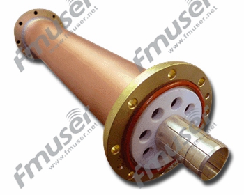
ਸਖ਼ਤ ਕੋਐਕਸ਼ੀਅਲ ਟ੍ਰਾਂਸਮਿਸ਼ਨ ਲਾਈਨਾਂ
ਸਖ਼ਤ ਕੋਐਕਸ਼ੀਅਲ ਟ੍ਰਾਂਸਮਿਸ਼ਨ ਲਾਈਨਾਂ ਵਿਸ਼ੇਸ਼ ਤੌਰ 'ਤੇ ਹਨ ਉੱਚ-ਪਾਵਰ ਆਰਐਫ ਐਪਲੀਕੇਸ਼ਨਾਂ ਲਈ ਇੰਜੀਨੀਅਰਿੰਗ, ਵਧੀਆ ਇਲੈਕਟ੍ਰੀਕਲ ਪ੍ਰਦਰਸ਼ਨ ਅਤੇ ਮਕੈਨੀਕਲ ਸਥਿਰਤਾ ਦੀ ਪੇਸ਼ਕਸ਼ ਕਰਦਾ ਹੈ। ਇਹ ਟਰਾਂਸਮਿਸ਼ਨ ਲਾਈਨਾਂ ਇੱਕ ਸਖ਼ਤ ਬਾਹਰੀ ਕੰਡਕਟਰ ਦੀ ਵਿਸ਼ੇਸ਼ਤਾ ਕਰਦੀਆਂ ਹਨ, ਕੁਸ਼ਲ ਸਿਗਨਲ ਪ੍ਰਸਾਰ ਨੂੰ ਯਕੀਨੀ ਬਣਾਉਂਦੀਆਂ ਹਨ ਅਤੇ ਸਿਗਨਲ ਦੇ ਨੁਕਸਾਨ ਨੂੰ ਘੱਟ ਕਰਦੀਆਂ ਹਨ। ਉਹ ਟਰਾਂਸਮਿਸ਼ਨ ਚੇਨ ਵਿੱਚ ਇੱਕ ਮਹੱਤਵਪੂਰਨ ਹਿੱਸੇ ਵਜੋਂ ਕੰਮ ਕਰਦੇ ਹਨ, ਟ੍ਰਾਂਸਮੀਟਰ ਨੂੰ ਸਬੰਧਿਤ ਕੇਬਲਾਂ ਨਾਲ ਜੋੜਦੇ ਹਨ।

ਆਪਟੀਕਲ ਕੇਬਲਾਂ ਆਪਟੀਕਲ ਫਾਈਬਰਾਂ ਰਾਹੀਂ ਸਿਗਨਲ ਪ੍ਰਸਾਰਿਤ ਕਰਨ ਦੇ ਤਰੀਕੇ ਦੇ ਸਮਾਨ, ਉੱਚ-ਫ੍ਰੀਕੁਐਂਸੀ ਸਿਗਨਲ ਟ੍ਰਾਂਸਮਿਸ਼ਨ ਲਈ ਸਖ਼ਤ ਟਰਾਂਸਮਿਸ਼ਨ ਲਾਈਨਾਂ ਦੀ ਵਰਤੋਂ ਕੀਤੀ ਜਾਂਦੀ ਹੈ। ਇਹਨਾਂ ਲਾਈਨਾਂ ਦੇ ਅੰਦਰ, ਇਲੈਕਟ੍ਰੋਮੈਗਨੈਟਿਕ ਤਰੰਗਾਂ ਕੋਰ ਲਾਈਨ ਅਤੇ ਫੀਡਰ ਦੇ ਵਿਚਕਾਰ ਅੱਗੇ-ਪਿੱਛੇ ਫੈਲਦੀਆਂ ਹਨ, ਜਦੋਂ ਕਿ ਸ਼ੀਲਡਿੰਗ ਪਰਤ ਬਾਹਰੀ ਦਖਲਅੰਦਾਜ਼ੀ ਦੇ ਸੰਕੇਤਾਂ ਨੂੰ ਪ੍ਰਭਾਵਸ਼ਾਲੀ ਢੰਗ ਨਾਲ ਰੋਕਦੀ ਹੈ। ਇਹ ਸ਼ੀਲਡਿੰਗ ਸਮਰੱਥਾ ਪ੍ਰਸਾਰਿਤ ਸਿਗਨਲਾਂ ਦੀ ਇਕਸਾਰਤਾ ਨੂੰ ਯਕੀਨੀ ਬਣਾਉਂਦੀ ਹੈ ਅਤੇ ਰੇਡੀਏਸ਼ਨ ਦੁਆਰਾ ਉਪਯੋਗੀ ਸਿਗਨਲਾਂ ਦੇ ਨੁਕਸਾਨ ਨੂੰ ਘਟਾਉਂਦੀ ਹੈ।
ਇਹ ਟਰਾਂਸਮਿਸ਼ਨ ਲਾਈਨਾਂ ਆਮ ਤੌਰ 'ਤੇ ਉਹਨਾਂ ਐਪਲੀਕੇਸ਼ਨਾਂ ਵਿੱਚ ਵਰਤੀਆਂ ਜਾਂਦੀਆਂ ਹਨ ਜਿਨ੍ਹਾਂ ਨੂੰ ਉੱਚ-ਪਾਵਰ ਹੈਂਡਲਿੰਗ ਅਤੇ ਘੱਟ ਸਿਗਨਲ ਨੁਕਸਾਨ ਦੀ ਲੋੜ ਹੁੰਦੀ ਹੈ, ਜਿਵੇਂ ਕਿ ਪ੍ਰਸਾਰਣ ਪ੍ਰਣਾਲੀਆਂ, ਸੈਲੂਲਰ ਨੈਟਵਰਕ, ਅਤੇ ਉੱਚ-ਆਵਿਰਤੀ ਸੰਚਾਰ ਪ੍ਰਣਾਲੀਆਂ। ਸਖ਼ਤ ਕੋਐਕਸ਼ੀਅਲ ਟ੍ਰਾਂਸਮਿਸ਼ਨ ਲਾਈਨਾਂ ਦੇ ਕੁਝ ਆਮ ਆਕਾਰਾਂ ਵਿੱਚ ਸ਼ਾਮਲ ਹਨ:
- 7/8" ਸਖ਼ਤ ਕੋਐਕਸ਼ੀਅਲ ਟ੍ਰਾਂਸਮਿਸ਼ਨ ਲਾਈਨ
- 1-5/8" ਸਖ਼ਤ ਕੋਐਕਸ਼ੀਅਲ ਟ੍ਰਾਂਸਮਿਸ਼ਨ ਲਾਈਨ
- 3-1/8" ਸਖ਼ਤ ਕੋਐਕਸ਼ੀਅਲ ਟ੍ਰਾਂਸਮਿਸ਼ਨ ਲਾਈਨ
- 4-1/16" ਸਖ਼ਤ ਕੋਐਕਸ਼ੀਅਲ ਟ੍ਰਾਂਸਮਿਸ਼ਨ ਲਾਈਨ
- 6-1/8" ਸਖ਼ਤ ਕੋਐਕਸ਼ੀਅਲ ਟ੍ਰਾਂਸਮਿਸ਼ਨ ਲਾਈਨ
ਸਟਾਕ ਵਿੱਚ ਉੱਚ ਗੁਣਵੱਤਾ ਦੀਆਂ ਸਖ਼ਤ ਲਾਈਨਾਂ:
https://www.fmradiobroadcast.com/product/detail/rigid-coaxial-transmission-line.html
ਕਠੋਰ ਕੋਐਕਸ਼ੀਅਲ ਟ੍ਰਾਂਸਮਿਸ਼ਨ ਲਾਈਨਾਂ ਕਿਵੇਂ ਕੰਮ ਕਰਦੀਆਂ ਹਨ
ਸਖ਼ਤ ਕੋਐਕਸ਼ੀਅਲ ਟ੍ਰਾਂਸਮਿਸ਼ਨ ਲਾਈਨਾਂ ਉਸੇ ਸਿਧਾਂਤ 'ਤੇ ਕੰਮ ਕਰਦੀਆਂ ਹਨ ਜਿਵੇਂ ਕਿ ਹੋਰ ਕੋਐਕਸ਼ੀਅਲ ਕੇਬਲ। ਉਹਨਾਂ ਵਿੱਚ ਇੱਕ ਕੇਂਦਰੀ ਕੰਡਕਟਰ, ਇੱਕ ਡਾਈਇਲੈਕਟ੍ਰਿਕ ਇੰਸੂਲੇਟਰ, ਇੱਕ ਬਾਹਰੀ ਕੰਡਕਟਰ, ਅਤੇ ਇੱਕ ਬਾਹਰੀ ਜੈਕਟ ਹੁੰਦੀ ਹੈ। ਅੰਦਰਲਾ ਕੰਡਕਟਰ RF ਸਿਗਨਲ ਰੱਖਦਾ ਹੈ, ਜਦੋਂ ਕਿ ਬਾਹਰੀ ਕੰਡਕਟਰ ਬਾਹਰੀ ਦਖਲਅੰਦਾਜ਼ੀ ਤੋਂ ਬਚਾਅ ਪ੍ਰਦਾਨ ਕਰਦਾ ਹੈ।
ਇਹਨਾਂ ਟਰਾਂਸਮਿਸ਼ਨ ਲਾਈਨਾਂ ਦਾ ਸਖ਼ਤ ਬਾਹਰੀ ਕੰਡਕਟਰ ਘੱਟੋ-ਘੱਟ ਸਿਗਨਲ ਲੀਕੇਜ ਨੂੰ ਯਕੀਨੀ ਬਣਾਉਂਦਾ ਹੈ ਅਤੇ ਸਿਗਨਲ ਦੇ ਨੁਕਸਾਨ ਨੂੰ ਘਟਾਉਂਦਾ ਹੈ। ਇਹ ਮਕੈਨੀਕਲ ਸਥਿਰਤਾ ਵੀ ਪ੍ਰਦਾਨ ਕਰਦਾ ਹੈ, ਜਿਸ ਨਾਲ ਟਰਾਂਸਮਿਸ਼ਨ ਲਾਈਨਾਂ ਉੱਚ-ਪਾਵਰ ਦੀਆਂ ਸਥਿਤੀਆਂ ਵਿੱਚ ਵੀ ਆਪਣੀ ਸ਼ਕਲ ਅਤੇ ਪ੍ਰਦਰਸ਼ਨ ਨੂੰ ਬਰਕਰਾਰ ਰੱਖ ਸਕਦੀਆਂ ਹਨ।
ਸਖ਼ਤ ਕੋਐਕਸ਼ੀਅਲ ਟ੍ਰਾਂਸਮਿਸ਼ਨ ਲਾਈਨਾਂ ਦੀ ਚੋਣ ਕਰਨਾ
ਸਖ਼ਤ ਕੋਐਕਸ਼ੀਅਲ ਟ੍ਰਾਂਸਮਿਸ਼ਨ ਲਾਈਨਾਂ ਦੀ ਚੋਣ ਕਰਦੇ ਸਮੇਂ ਹੇਠਾਂ ਦਿੱਤੇ ਕਾਰਕਾਂ 'ਤੇ ਗੌਰ ਕਰੋ:
- ਪਾਵਰ ਹੈਂਡਲਿੰਗ ਸਮਰੱਥਾ: ਆਪਣੀ RF ਐਪਲੀਕੇਸ਼ਨ ਦੀਆਂ ਪਾਵਰ ਹੈਂਡਲਿੰਗ ਲੋੜਾਂ ਦਾ ਪਤਾ ਲਗਾਓ। ਇੱਕ ਸਖ਼ਤ ਕੋਐਕਸ਼ੀਅਲ ਟਰਾਂਸਮਿਸ਼ਨ ਲਾਈਨ ਚੁਣੋ ਜੋ ਸਿਗਨਲ ਦੇ ਮਹੱਤਵਪੂਰਨ ਨੁਕਸਾਨ ਜਾਂ ਗਿਰਾਵਟ ਦੇ ਬਿਨਾਂ ਲੋੜੀਂਦੇ ਪਾਵਰ ਪੱਧਰਾਂ ਨੂੰ ਸੰਭਾਲ ਸਕਦੀ ਹੈ।
- ਸਿਗਨਲ ਦਾ ਨੁਕਸਾਨ: ਆਪਣੀ ਲੋੜੀਦੀ ਬਾਰੰਬਾਰਤਾ ਸੀਮਾ 'ਤੇ ਟ੍ਰਾਂਸਮਿਸ਼ਨ ਲਾਈਨ ਦੀਆਂ ਸਿਗਨਲ ਨੁਕਸਾਨ ਦੀਆਂ ਵਿਸ਼ੇਸ਼ਤਾਵਾਂ ਦਾ ਮੁਲਾਂਕਣ ਕਰੋ। ਘੱਟ ਸਿਗਨਲ ਦਾ ਨੁਕਸਾਨ ਲੰਬੀ ਦੂਰੀ 'ਤੇ ਬਿਹਤਰ ਸਿਗਨਲ ਇਕਸਾਰਤਾ ਨੂੰ ਯਕੀਨੀ ਬਣਾਉਂਦਾ ਹੈ।
- ਵਾਤਾਵਰਣ ਸੰਬੰਧੀ ਵਿਚਾਰ: ਵਾਤਾਵਰਣ ਦੀਆਂ ਸਥਿਤੀਆਂ ਦਾ ਮੁਲਾਂਕਣ ਕਰੋ ਜਿਨ੍ਹਾਂ ਨਾਲ ਟ੍ਰਾਂਸਮਿਸ਼ਨ ਲਾਈਨ ਦਾ ਸਾਹਮਣਾ ਕੀਤਾ ਜਾਵੇਗਾ, ਜਿਵੇਂ ਕਿ ਤਾਪਮਾਨ, ਨਮੀ, ਅਤੇ UV ਪ੍ਰਤੀਰੋਧ। ਯਕੀਨੀ ਬਣਾਓ ਕਿ ਚੁਣੀ ਗਈ ਟਰਾਂਸਮਿਸ਼ਨ ਲਾਈਨ ਤੁਹਾਡੀ ਐਪਲੀਕੇਸ਼ਨ ਦੀਆਂ ਖਾਸ ਵਾਤਾਵਰਨ ਲੋੜਾਂ ਲਈ ਢੁਕਵੀਂ ਹੈ।
- ਬਾਰੰਬਾਰਤਾ ਸੀਮਾ: ਪੁਸ਼ਟੀ ਕਰੋ ਕਿ ਟ੍ਰਾਂਸਮਿਸ਼ਨ ਲਾਈਨ ਤੁਹਾਡੀ ਐਪਲੀਕੇਸ਼ਨ ਲਈ ਲੋੜੀਂਦੀ ਬਾਰੰਬਾਰਤਾ ਸੀਮਾ ਦਾ ਸਮਰਥਨ ਕਰਦੀ ਹੈ। ਵੱਖ-ਵੱਖ ਸਖ਼ਤ ਕੋਐਕਸ਼ੀਅਲ ਟਰਾਂਸਮਿਸ਼ਨ ਲਾਈਨਾਂ ਨੂੰ ਖਾਸ ਬਾਰੰਬਾਰਤਾ ਰੇਂਜਾਂ ਲਈ ਤਿਆਰ ਕੀਤਾ ਗਿਆ ਹੈ, ਇਸਲਈ ਇੱਕ ਚੁਣੋ ਜੋ ਤੁਹਾਡੀਆਂ ਬਾਰੰਬਾਰਤਾ ਦੀਆਂ ਲੋੜਾਂ ਨਾਲ ਮੇਲ ਖਾਂਦਾ ਹੈ।
- ਅਨੁਕੂਲਤਾ: ਯਕੀਨੀ ਬਣਾਓ ਕਿ ਟ੍ਰਾਂਸਮਿਸ਼ਨ ਲਾਈਨ ਤੁਹਾਡੇ RF ਸਿਸਟਮ ਦੇ ਕਨੈਕਟਰਾਂ ਅਤੇ ਹੋਰ ਹਿੱਸਿਆਂ ਦੇ ਅਨੁਕੂਲ ਹੈ। ਪੁਸ਼ਟੀ ਕਰੋ ਕਿ ਚੁਣੀ ਗਈ ਟਰਾਂਸਮਿਸ਼ਨ ਲਾਈਨ ਲਈ ਕਨੈਕਟਰ ਅਤੇ ਸਮਾਪਤੀ ਆਸਾਨੀ ਨਾਲ ਉਪਲਬਧ ਹਨ ਅਤੇ ਤੁਹਾਡੀ ਖਾਸ ਐਪਲੀਕੇਸ਼ਨ ਲਈ ਢੁਕਵੇਂ ਹਨ।
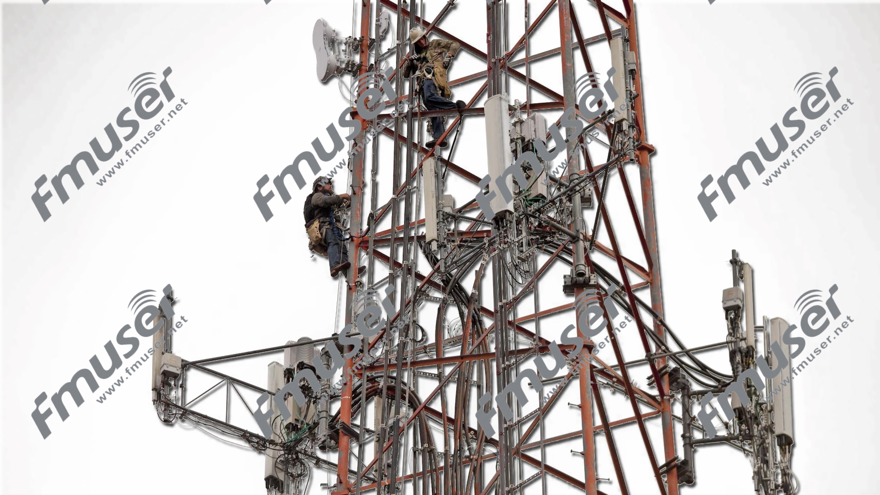
ਟਾਵਰ ਜਾਂ ਮਸਤ
ਇੱਕ ਟਾਵਰ ਜਾਂ ਮਾਸਟ ਇੱਕ ਫ੍ਰੀਸਟੈਂਡਿੰਗ ਢਾਂਚਾ ਹੈ ਜੋ ਐਂਟੀਨਾ ਅਤੇ ਸੰਬੰਧਿਤ ਉਪਕਰਣਾਂ ਨੂੰ ਸੁਰੱਖਿਅਤ ਢੰਗ ਨਾਲ ਅਨੁਕੂਲਿਤ ਕਰਨ ਲਈ ਤਿਆਰ ਕੀਤਾ ਗਿਆ ਹੈ। ਇਹ ਸਰਵੋਤਮ ਐਂਟੀਨਾ ਪ੍ਰਦਰਸ਼ਨ ਲਈ ਲੋੜੀਂਦੀ ਉਚਾਈ ਅਤੇ ਸਥਿਰਤਾ ਪ੍ਰਦਾਨ ਕਰਦਾ ਹੈ। ਟਾਵਰ ਆਮ ਤੌਰ 'ਤੇ ਸਟੀਲ ਜਾਂ ਐਲੂਮੀਨੀਅਮ ਦੇ ਬਣੇ ਹੁੰਦੇ ਹਨ, ਜੋ ਵਾਤਾਵਰਣ ਦੇ ਤੱਤਾਂ ਦੇ ਟਿਕਾਊਤਾ ਅਤੇ ਵਿਰੋਧ ਨੂੰ ਯਕੀਨੀ ਬਣਾਉਂਦੇ ਹਨ।
ਕਿਦਾ ਚਲਦਾ?
ਇੱਕ ਟਾਵਰ ਜਾਂ ਮਾਸਟ ਦਾ ਮੁੱਖ ਕੰਮ ਐਂਟੀਨਾ ਨੂੰ ਇੱਕ ਰਣਨੀਤਕ ਉਚਾਈ ਤੱਕ ਉੱਚਾ ਕਰਨਾ ਹੈ ਜੋ ਲੰਬੀ ਦੂਰੀ ਅਤੇ ਚੌੜੇ ਖੇਤਰਾਂ ਵਿੱਚ ਸਿਗਨਲ ਦੇ ਪ੍ਰਸਾਰ ਦੀ ਸਹੂਲਤ ਦਿੰਦਾ ਹੈ। ਐਂਟੀਨਾ ਨੂੰ ਉੱਚੇ ਸਥਾਨ 'ਤੇ ਰੱਖ ਕੇ, ਉਹ ਰੁਕਾਵਟਾਂ ਨੂੰ ਦੂਰ ਕਰ ਸਕਦੇ ਹਨ ਅਤੇ ਸਿਗਨਲ ਰੁਕਾਵਟ ਨੂੰ ਘੱਟ ਕਰ ਸਕਦੇ ਹਨ, ਨਤੀਜੇ ਵਜੋਂ ਵਧੀ ਹੋਈ ਕਵਰੇਜ ਅਤੇ ਸਿਗਨਲ ਗੁਣਵੱਤਾ ਵਿੱਚ ਸੁਧਾਰ ਹੁੰਦਾ ਹੈ।
ਟਾਵਰਾਂ ਜਾਂ ਮਾਸਟਾਂ ਨੂੰ ਹਵਾ ਦੇ ਭਾਰ, ਭੂਚਾਲ ਦੀਆਂ ਸ਼ਕਤੀਆਂ ਅਤੇ ਹੋਰ ਵਾਤਾਵਰਣਕ ਕਾਰਕਾਂ ਦਾ ਸਾਮ੍ਹਣਾ ਕਰਨ ਲਈ ਇੰਜਨੀਅਰ ਕੀਤਾ ਗਿਆ ਹੈ ਜੋ ਐਂਟੀਨਾ ਸਿਸਟਮ ਦੀ ਸਥਿਰਤਾ ਨੂੰ ਪ੍ਰਭਾਵਤ ਕਰ ਸਕਦੇ ਹਨ। ਉਹ ਢਾਂਚਾਗਤ ਤੌਰ 'ਤੇ ਮਜ਼ਬੂਤ ਹੋਣ ਲਈ ਤਿਆਰ ਕੀਤੇ ਗਏ ਹਨ, ਟਾਵਰ 'ਤੇ ਜਾਂ ਨੇੜੇ ਕੰਮ ਕਰਨ ਵਾਲੇ ਕਰਮਚਾਰੀਆਂ ਦੀ ਸੁਰੱਖਿਆ ਨੂੰ ਯਕੀਨੀ ਬਣਾਉਂਦੇ ਹੋਏ।
AM, FM, ਅਤੇ TV ਸਟੇਸ਼ਨਾਂ ਲਈ ਅੰਤਰ
ਜਦੋਂ ਕਿ ਟਾਵਰ ਜਾਂ ਮਾਸਟ ਵੱਖ-ਵੱਖ ਐਪਲੀਕੇਸ਼ਨਾਂ ਵਿੱਚ ਐਂਟੀਨਾ ਪ੍ਰਣਾਲੀਆਂ ਲਈ ਸਹਾਇਤਾ ਢਾਂਚੇ ਵਜੋਂ ਕੰਮ ਕਰਦੇ ਹਨ, ਉਹਨਾਂ ਦੇ ਡਿਜ਼ਾਈਨ ਅਤੇ AM, FM, ਅਤੇ TV ਸਟੇਸ਼ਨਾਂ ਲਈ ਲੋੜਾਂ ਵਿੱਚ ਮਹੱਤਵਪੂਰਨ ਅੰਤਰ ਹਨ। ਇਹ ਅੰਤਰ ਮੁੱਖ ਤੌਰ 'ਤੇ ਸਿਗਨਲਾਂ ਦੀਆਂ ਖਾਸ ਵਿਸ਼ੇਸ਼ਤਾਵਾਂ ਅਤੇ ਹਰੇਕ ਪ੍ਰਸਾਰਣ ਫਾਰਮੈਟ ਦੀਆਂ ਕਵਰੇਜ ਲੋੜਾਂ ਤੋਂ ਪੈਦਾ ਹੁੰਦੇ ਹਨ।
- AM ਸਟੇਸ਼ਨ ਟਾਵਰ ਜਾਂ ਮਾਸਟ: AM ਰੇਡੀਓ ਸਟੇਸ਼ਨਾਂ ਨੂੰ ਆਮ ਤੌਰ 'ਤੇ AM ਸਿਗਨਲਾਂ ਦੀ ਲੰਮੀ ਤਰੰਗ-ਲੰਬਾਈ ਦੇ ਕਾਰਨ ਉੱਚੇ ਅਤੇ ਵਧੇਰੇ ਮਜ਼ਬੂਤ ਟਾਵਰਾਂ ਦੀ ਲੋੜ ਹੁੰਦੀ ਹੈ। ਇਹ ਸਿਗਨਲ ਜ਼ਮੀਨ ਦੇ ਨਾਲ-ਨਾਲ ਪ੍ਰਸਾਰਿਤ ਹੁੰਦੇ ਹਨ, ਉੱਚਾਈ ਵਾਲੇ ਟਾਵਰਾਂ ਦੀ ਲੋੜ ਹੁੰਦੀ ਹੈ ਜੋ ਵਿਆਪਕ ਕਵਰੇਜ ਦੀ ਇਜਾਜ਼ਤ ਦਿੰਦੇ ਹਨ ਅਤੇ ਰੁਕਾਵਟਾਂ ਨੂੰ ਦੂਰ ਕਰਦੇ ਹਨ। AM ਸਟੇਸ਼ਨ ਟਾਵਰ ਆਮ ਤੌਰ 'ਤੇ ਆਧਾਰਿਤ ਹੁੰਦੇ ਹਨ ਅਤੇ ਪਾਸੇ ਦੀਆਂ ਤਾਕਤਾਂ ਦੇ ਵਿਰੁੱਧ ਵਾਧੂ ਸਥਿਰਤਾ ਪ੍ਰਦਾਨ ਕਰਨ ਲਈ ਗਾਈ ਤਾਰ ਦੀ ਇੱਕ ਪ੍ਰਣਾਲੀ ਨੂੰ ਸ਼ਾਮਲ ਕਰ ਸਕਦੇ ਹਨ।
- ਐਫਐਮ ਸਟੇਸ਼ਨ ਟਾਵਰ ਜਾਂ ਮਾਸਟ: FM ਰੇਡੀਓ ਸਿਗਨਲਾਂ ਦੀ ਤਰੰਗ-ਲੰਬਾਈ AM ਸਿਗਨਲਾਂ ਦੇ ਮੁਕਾਬਲੇ ਘੱਟ ਹੁੰਦੀ ਹੈ, ਜਿਸ ਨਾਲ ਉਹ ਵਧੇਰੇ ਸਿੱਧੀ ਲਾਈਨ-ਆਫ਼-ਨਜ਼ਰ ਤਰੀਕੇ ਨਾਲ ਪ੍ਰਚਾਰ ਕਰ ਸਕਦੇ ਹਨ। ਨਤੀਜੇ ਵਜੋਂ, FM ਸਟੇਸ਼ਨ ਟਾਵਰ AM ਟਾਵਰਾਂ ਦੇ ਮੁਕਾਬਲੇ ਉਚਾਈ ਵਿੱਚ ਛੋਟੇ ਹੋ ਸਕਦੇ ਹਨ। FM ਟਾਵਰਾਂ ਲਈ ਫੋਕਸ ਲਾਈਨ-ਆਫ-ਸਾਈਟ ਟ੍ਰਾਂਸਮਿਸ਼ਨ ਨੂੰ ਪ੍ਰਾਪਤ ਕਰਨ, ਰੁਕਾਵਟਾਂ ਨੂੰ ਘੱਟ ਕਰਨ ਅਤੇ ਸਿਗਨਲ ਕਵਰੇਜ ਨੂੰ ਵੱਧ ਤੋਂ ਵੱਧ ਕਰਨ ਲਈ ਐਂਟੀਨਾ ਨੂੰ ਇੱਕ ਅਨੁਕੂਲ ਉਚਾਈ 'ਤੇ ਸਥਾਪਤ ਕਰਨਾ ਹੈ।
- ਟੀਵੀ ਸਟੇਸ਼ਨ ਟਾਵਰ ਜਾਂ ਮਾਸਟ: ਟੀਵੀ ਸਟੇਸ਼ਨਾਂ ਨੂੰ ਐਂਟੀਨਾ ਦਾ ਸਮਰਥਨ ਕਰਨ ਲਈ ਟਾਵਰ ਜਾਂ ਮਾਸਟ ਦੀ ਲੋੜ ਹੁੰਦੀ ਹੈ ਜੋ ਵੱਖ-ਵੱਖ ਟੀਵੀ ਚੈਨਲਾਂ ਲਈ ਫ੍ਰੀਕੁਐਂਸੀ ਦੀ ਇੱਕ ਵਿਸ਼ਾਲ ਸ਼੍ਰੇਣੀ ਨੂੰ ਸੰਚਾਰਿਤ ਕਰਦੇ ਹਨ। ਇਹ ਟਾਵਰ ਟੀਵੀ ਪ੍ਰਸਾਰਣ ਵਿੱਚ ਵਰਤੀਆਂ ਜਾਣ ਵਾਲੀਆਂ ਉੱਚੀਆਂ ਬਾਰੰਬਾਰਤਾਵਾਂ ਨੂੰ ਅਨੁਕੂਲ ਕਰਨ ਲਈ ਐਫਐਮ ਟਾਵਰਾਂ ਨਾਲੋਂ ਉੱਚੇ ਹੁੰਦੇ ਹਨ। ਟੀਵੀ ਸਟੇਸ਼ਨ ਟਾਵਰਾਂ ਵਿੱਚ ਅਕਸਰ ਕਈ ਐਂਟੀਨਾ ਸ਼ਾਮਲ ਹੁੰਦੇ ਹਨ ਅਤੇ ਦਿਸ਼ਾ ਨਿਰਦੇਸ਼ਕ ਰੇਡੀਏਸ਼ਨ ਪੈਟਰਨ ਪ੍ਰਦਾਨ ਕਰਨ ਲਈ ਇੰਜਨੀਅਰ ਹੁੰਦੇ ਹਨ, ਖਾਸ ਖੇਤਰਾਂ ਵਿੱਚ ਨਿਸ਼ਾਨਾ ਕਵਰੇਜ ਦੀ ਆਗਿਆ ਦਿੰਦੇ ਹੋਏ।
ਢਾਂਚਾਗਤ ਵਿਚਾਰ ਅਤੇ ਨਿਯਮ
ਪ੍ਰਸਾਰਣ ਫਾਰਮੈਟ ਦੀ ਪਰਵਾਹ ਕੀਤੇ ਬਿਨਾਂ, ਟਾਵਰ ਜਾਂ ਮਾਸਟ ਸਥਾਪਨਾਵਾਂ ਲਈ ਢਾਂਚਾਗਤ ਇਕਸਾਰਤਾ ਅਤੇ ਨਿਯਮਾਂ ਦੀ ਪਾਲਣਾ ਮਹੱਤਵਪੂਰਨ ਰਹਿੰਦੀ ਹੈ। ਵੱਖ-ਵੱਖ ਵਾਤਾਵਰਣ ਦੀਆਂ ਸਥਿਤੀਆਂ ਦੇ ਅਧੀਨ ਢਾਂਚੇ ਦੀ ਸੁਰੱਖਿਆ ਅਤੇ ਸਥਿਰਤਾ ਨੂੰ ਯਕੀਨੀ ਬਣਾਉਣ ਲਈ ਹਵਾ ਦੇ ਭਾਰ, ਭਾਰ ਦੀ ਵੰਡ, ਬਰਫ਼ ਦੀ ਲੋਡਿੰਗ, ਅਤੇ ਭੂਚਾਲ ਸੰਬੰਧੀ ਵਿਚਾਰਾਂ ਵਰਗੇ ਕਾਰਕਾਂ ਨੂੰ ਧਿਆਨ ਵਿੱਚ ਰੱਖਣਾ ਚਾਹੀਦਾ ਹੈ।
ਇਸ ਤੋਂ ਇਲਾਵਾ, ਹਰੇਕ ਦੇਸ਼ ਜਾਂ ਖੇਤਰ ਵਿੱਚ ਟਾਵਰ ਜਾਂ ਮਾਸਟ ਸਥਾਪਨਾਵਾਂ ਨੂੰ ਨਿਯੰਤਰਿਤ ਕਰਨ ਵਾਲੇ ਖਾਸ ਨਿਯਮ ਅਤੇ ਦਿਸ਼ਾ-ਨਿਰਦੇਸ਼ ਹੋ ਸਕਦੇ ਹਨ, ਜਿਸ ਵਿੱਚ ਰੋਸ਼ਨੀ, ਪੇਂਟਿੰਗ ਅਤੇ ਹਵਾਬਾਜ਼ੀ ਸੁਰੱਖਿਆ ਲਈ ਲੋੜਾਂ ਸ਼ਾਮਲ ਹਨ।
ਇੱਥੇ ਇੱਕ ਤੁਲਨਾ ਸਾਰਣੀ ਹੈ ਜੋ AM, FM, ਅਤੇ TV ਸਟੇਸ਼ਨਾਂ ਵਿੱਚ ਵਰਤੇ ਜਾਂਦੇ ਟਾਵਰਾਂ ਜਾਂ ਮਾਸਟਾਂ ਵਿਚਕਾਰ ਮੁੱਖ ਅੰਤਰਾਂ ਨੂੰ ਉਜਾਗਰ ਕਰਦੀ ਹੈ:
| ਪਹਿਲੂ | AM ਸਟੇਸ਼ਨ ਟਾਵਰ/ਮਾਸਟ | FM ਸਟੇਸ਼ਨ ਟਾਵਰ/ਮਾਸਟਸ | ਟੀਵੀ ਸਟੇਸ਼ਨ ਟਾਵਰ/ਮਾਸਟ |
|---|---|---|---|
| ਉਚਾਈ ਦੀ ਲੋੜ | AM ਸਿਗਨਲਾਂ ਦੀ ਲੰਮੀ ਤਰੰਗ-ਲੰਬਾਈ ਕਾਰਨ ਲੰਬਾ | ਲਾਈਨ-ਆਫ-ਸਾਈਟ ਪ੍ਰਸਾਰ ਲਈ AM ਟਾਵਰਾਂ ਨਾਲੋਂ ਮੁਕਾਬਲਤਨ ਛੋਟਾ | ਉੱਚ ਟੀਵੀ ਪ੍ਰਸਾਰਣ ਫ੍ਰੀਕੁਐਂਸੀ ਨੂੰ ਅਨੁਕੂਲ ਕਰਨ ਲਈ ਐਫਐਮ ਟਾਵਰਾਂ ਤੋਂ ਉੱਚਾ |
| ਸਿਗਨਲ ਪ੍ਰਸਾਰ | ਵਿਆਪਕ ਕਵਰੇਜ ਦੇ ਨਾਲ ਜ਼ਮੀਨੀ-ਲਹਿਰ ਦਾ ਪ੍ਰਸਾਰ | ਸਿੱਧੇ ਪ੍ਰਸਾਰਣ 'ਤੇ ਫੋਕਸ ਦੇ ਨਾਲ ਲਾਈਨ-ਆਫ-ਸੀਟ ਪ੍ਰਸਾਰ | ਖਾਸ ਖੇਤਰਾਂ ਵਿੱਚ ਨਿਸ਼ਾਨਾ ਕਵਰੇਜ ਦੇ ਨਾਲ ਲਾਈਨ-ਆਫ-ਸਾਈਟ ਟ੍ਰਾਂਸਮਿਸ਼ਨ |
| ਢਾਂਚਾਗਤ ਵਿਚਾਰ | ਮਜਬੂਤ ਉਸਾਰੀ ਅਤੇ ਗਰਾਉਂਡਿੰਗ ਦੀ ਲੋੜ ਹੈ, ਗਾਈ ਤਾਰਾਂ ਨੂੰ ਸ਼ਾਮਲ ਕੀਤਾ ਜਾ ਸਕਦਾ ਹੈ | ਉੱਚਾਈ ਅਤੇ ਲਾਈਨ-ਆਫ-ਨਜ਼ਰ ਦੇ ਪ੍ਰਸਾਰ ਲਈ ਮਜ਼ਬੂਤ ਡਿਜ਼ਾਈਨ | ਮਲਟੀਪਲ ਐਂਟੀਨਾ ਅਤੇ ਦਿਸ਼ਾ-ਨਿਰਦੇਸ਼ ਰੇਡੀਏਸ਼ਨ ਪੈਟਰਨਾਂ ਨੂੰ ਅਨੁਕੂਲ ਬਣਾਉਣ ਲਈ ਮਜ਼ਬੂਤ ਡਿਜ਼ਾਈਨ |
| ਰੈਗੂਲੇਟਰੀ ਪਾਲਣਾ | ਟਾਵਰ ਦੀ ਉਚਾਈ ਅਤੇ ਗਰਾਉਂਡਿੰਗ ਨੂੰ ਨਿਯੰਤਰਿਤ ਕਰਨ ਵਾਲੇ ਨਿਯਮਾਂ ਦੀ ਪਾਲਣਾ | ਟਾਵਰ ਦੀ ਉਚਾਈ ਅਤੇ ਲਾਈਨ-ਆਫ਼-ਨਜ਼ਰ ਲਈ ਨਿਯਮਾਂ ਦੀ ਪਾਲਣਾ | ਟਾਵਰ ਦੀ ਉਚਾਈ, ਮਲਟੀਪਲ ਐਂਟੀਨਾ, ਅਤੇ ਦਿਸ਼ਾਤਮਕ ਰੇਡੀਏਸ਼ਨ ਪੈਟਰਨਾਂ ਲਈ ਨਿਯਮਾਂ ਦੀ ਪਾਲਣਾ |
| ਪੇਸ਼ੇਵਰ ਮਸ਼ਵਰਾ | ਪਾਲਣਾ, ਸੁਰੱਖਿਆ ਅਤੇ ਅਨੁਕੂਲਤਾ ਲਈ ਮਹੱਤਵਪੂਰਨ | ਪਾਲਣਾ, ਸੁਰੱਖਿਆ, ਅਤੇ ਅਨੁਕੂਲ ਲਾਈਨ-ਆਫ-ਸਾਈਟ ਕਵਰੇਜ ਲਈ ਮਹੱਤਵਪੂਰਨ | ਕਈ ਟੀਵੀ ਚੈਨਲਾਂ ਲਈ ਪਾਲਣਾ, ਸੁਰੱਖਿਆ ਅਤੇ ਅਨੁਕੂਲ ਕਵਰੇਜ ਲਈ ਮਹੱਤਵਪੂਰਨ |
ਸੱਜਾ ਟਾਵਰ ਜਾਂ ਮਾਸਟ ਚੁਣਨਾ
ਐਂਟੀਨਾ ਸਿਸਟਮ ਲਈ ਟਾਵਰ ਜਾਂ ਮਾਸਟ ਦੀ ਚੋਣ ਕਰਦੇ ਸਮੇਂ, ਕਈ ਕਾਰਕਾਂ ਨੂੰ ਵਿਚਾਰਨ ਦੀ ਲੋੜ ਹੁੰਦੀ ਹੈ:
- ਉਚਾਈ ਦੀਆਂ ਲੋੜਾਂ: ਲੋੜੀਂਦੇ ਕਵਰੇਜ ਖੇਤਰ ਅਤੇ ਪ੍ਰਸਾਰਿਤ ਜਾਂ ਪ੍ਰਾਪਤ ਕੀਤੇ ਜਾਣ ਵਾਲੇ RF ਸਿਗਨਲਾਂ ਦੀਆਂ ਵਿਸ਼ੇਸ਼ ਵਿਸ਼ੇਸ਼ਤਾਵਾਂ ਦੇ ਆਧਾਰ 'ਤੇ ਲੋੜੀਂਦੀ ਉਚਾਈ ਦਾ ਪਤਾ ਲਗਾਓ।
- ਲੋਡ ਸਮਰੱਥਾ: ਇਹ ਯਕੀਨੀ ਬਣਾਉਣ ਲਈ ਕਿ ਟਾਵਰ ਜਾਂ ਮਾਸਟ ਸੁਰੱਖਿਅਤ ਢੰਗ ਨਾਲ ਇੱਛਤ ਲੋਡ ਦਾ ਸਮਰਥਨ ਕਰ ਸਕਦੇ ਹਨ, ਐਂਟੀਨਾ ਅਤੇ ਸੰਬੰਧਿਤ ਉਪਕਰਣਾਂ ਦੇ ਭਾਰ ਅਤੇ ਆਕਾਰ 'ਤੇ ਗੌਰ ਕਰੋ।
- ਵਾਤਾਵਰਣ ਦੇ ਹਾਲਾਤ: ਇੰਸਟਾਲੇਸ਼ਨ ਸਾਈਟ 'ਤੇ ਵਾਤਾਵਰਣ ਦੀਆਂ ਸਥਿਤੀਆਂ ਦਾ ਮੁਲਾਂਕਣ ਕਰੋ, ਜਿਸ ਵਿੱਚ ਹਵਾ ਦੀ ਗਤੀ, ਤਾਪਮਾਨ ਦੇ ਭਿੰਨਤਾਵਾਂ, ਅਤੇ ਬਰਫ਼ ਜਾਂ ਬਰਫ਼ ਦੇ ਇਕੱਠਾ ਹੋਣ ਦੀ ਸੰਭਾਵਨਾ ਸ਼ਾਮਲ ਹੈ। ਇੱਕ ਟਾਵਰ ਜਾਂ ਮਾਸਟ ਚੁਣੋ ਜੋ ਇਹਨਾਂ ਹਾਲਤਾਂ ਦਾ ਸਾਮ੍ਹਣਾ ਕਰਨ ਲਈ ਤਿਆਰ ਕੀਤਾ ਗਿਆ ਹੈ।
- ਰੈਗੂਲੇਟਰੀ ਪਾਲਣਾ: ਸੁਰੱਖਿਆ ਅਤੇ ਕਾਨੂੰਨੀ ਕਾਰਨਾਂ ਕਰਕੇ ਸਥਾਨਕ ਨਿਯਮਾਂ ਅਤੇ ਬਿਲਡਿੰਗ ਕੋਡਾਂ ਦੀ ਪਾਲਣਾ ਮਹੱਤਵਪੂਰਨ ਹੈ। ਯਕੀਨੀ ਬਣਾਓ ਕਿ ਚੁਣਿਆ ਟਾਵਰ ਜਾਂ ਮਾਸਟ ਸਾਰੇ ਲਾਗੂ ਹੋਣ ਵਾਲੇ ਮਿਆਰਾਂ ਅਤੇ ਲੋੜਾਂ ਨੂੰ ਪੂਰਾ ਕਰਦਾ ਹੈ।
- ਭਵਿੱਖ ਦਾ ਵਿਸਥਾਰ: ਭਵਿੱਖ ਵਿੱਚ ਵਿਕਾਸ ਜਾਂ ਐਂਟੀਨਾ ਸਿਸਟਮ ਵਿੱਚ ਤਬਦੀਲੀਆਂ ਦਾ ਅੰਦਾਜ਼ਾ ਲਗਾਓ ਅਤੇ ਇੱਕ ਟਾਵਰ ਜਾਂ ਮਾਸਟ ਚੁਣੋ ਜੋ ਲੋੜ ਪੈਣ 'ਤੇ ਵਾਧੂ ਐਂਟੀਨਾ ਜਾਂ ਸਾਜ਼ੋ-ਸਾਮਾਨ ਨੂੰ ਅਨੁਕੂਲਿਤ ਕਰ ਸਕੇ।
ਇਸੇ ਐਫਐਮ ਟ੍ਰਾਂਸਮੀਟਿੰਗ ਟਾਵਰ ਮਹੱਤਵਪੂਰਨ ਹੈ?
ਟਾਵਰ ਜਾਂ ਤਾਂ ਖੁਦ ਇੱਕ ਐਂਟੀਨਾ ਵਜੋਂ ਕੰਮ ਕਰੇਗਾ ਜਾਂ ਇਸਦੇ ਢਾਂਚੇ 'ਤੇ ਇੱਕ ਜਾਂ ਇੱਕ ਤੋਂ ਵੱਧ ਐਂਟੀਨਾ ਦਾ ਸਮਰਥਨ ਕਰੇਗਾ ਕਿਉਂਕਿ ਉਹਨਾਂ ਨੂੰ ਮਾਈਕ੍ਰੋਵੇਵ ਪਕਵਾਨਾਂ ਸਮੇਤ ਲੰਬੀ ਦੂਰੀ 'ਤੇ ਸ਼ਕਤੀਸ਼ਾਲੀ ਸਿਗਨਲ ਭੇਜਣੇ ਪੈਂਦੇ ਹਨ। ਇਹ ਐਂਟੀਨਾ ਰੇਡੀਓਫ੍ਰੀਕੁਐਂਸੀ (ਆਰਐਫ) ਇਲੈਕਟ੍ਰੋਮੈਗਨੈਟਿਕ ਐਨਰਜੀ (ਈਐਮਈ) ਨੂੰ ਛੱਡਦੇ ਹਨ। ਪਰ ਤੁਹਾਨੂੰ ਘਰ ਵਿੱਚ ਆਪਣੇ ਟੀਵੀ ਜਾਂ ਰੇਡੀਓ 'ਤੇ ਕਿਸੇ ਵੀ ਵੱਡੀ ਚੀਜ਼ ਦੀ ਲੋੜ ਨਹੀਂ ਹੈ: ਇੱਕ ਬਹੁਤ ਛੋਟਾ ਐਂਟੀਨਾ ਕੰਮ ਨੂੰ ਵਧੀਆ ਕਰੇਗਾ।
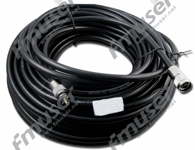
ਆਰਐਫ ਕੋਐਕਸ਼ੀਅਲ ਕੇਬਲ
ਆਰਐਫ ਕੋਐਕਸ਼ੀਅਲ ਕੇਬਲ ਉੱਚ-ਫ੍ਰੀਕੁਐਂਸੀ ਸਿਗਨਲਾਂ ਦੇ ਪ੍ਰਸਾਰਣ ਵਿੱਚ ਜ਼ਰੂਰੀ ਹਿੱਸੇ ਹਨ। ਉਹਨਾਂ ਨੂੰ ਕਈ ਮੁੱਖ ਤੱਤਾਂ ਨਾਲ ਬਣਾਇਆ ਗਿਆ ਹੈ: ਇੱਕ ਕੇਂਦਰੀ ਕੰਡਕਟਰ, ਡਾਈਇਲੈਕਟ੍ਰਿਕ ਇਨਸੂਲੇਸ਼ਨ, ਸ਼ੀਲਡਿੰਗ, ਅਤੇ ਇੱਕ ਬਾਹਰੀ ਜੈਕਟ। ਇਹ ਡਿਜ਼ਾਈਨ ਸਿਗਨਲ ਦੇ ਨੁਕਸਾਨ ਅਤੇ ਬਾਹਰੀ ਦਖਲਅੰਦਾਜ਼ੀ ਨੂੰ ਘੱਟ ਕਰਦੇ ਹੋਏ ਪ੍ਰਭਾਵੀ ਸਿਗਨਲ ਪ੍ਰਸਾਰਣ ਨੂੰ ਸਮਰੱਥ ਬਣਾਉਂਦਾ ਹੈ।

ਆਰਐਫ ਕੋਐਕਸ਼ੀਅਲ ਕੇਬਲ ਕਿਵੇਂ ਕੰਮ ਕਰਦੇ ਹਨ?
RF ਕੋਐਕਸ਼ੀਅਲ ਕੇਬਲ ਕੇਂਦਰੀ ਕੰਡਕਟਰ ਦੇ ਨਾਲ ਉੱਚ-ਫ੍ਰੀਕੁਐਂਸੀ ਸਿਗਨਲਾਂ ਨੂੰ ਸੰਚਾਰਿਤ ਕਰਕੇ ਕੰਮ ਕਰਦੇ ਹਨ ਜਦੋਂ ਕਿ ਢਾਲ ਸਿਗਨਲ ਲੀਕ ਅਤੇ ਬਾਹਰੀ ਦਖਲਅੰਦਾਜ਼ੀ ਨੂੰ ਰੋਕਦੀ ਹੈ। ਕੇਂਦਰੀ ਕੰਡਕਟਰ, ਖਾਸ ਤੌਰ 'ਤੇ ਠੋਸ ਜਾਂ ਬ੍ਰੇਡਡ ਤਾਂਬੇ ਦੀਆਂ ਤਾਰਾਂ ਦਾ ਬਣਿਆ, ਬਿਜਲੀ ਦੇ ਸਿਗਨਲ ਨੂੰ ਸੰਭਾਲਦਾ ਹੈ। ਇਹ ਡਾਈਇਲੈਕਟ੍ਰਿਕ ਇਨਸੂਲੇਸ਼ਨ ਦੀ ਇੱਕ ਪਰਤ ਨਾਲ ਘਿਰਿਆ ਹੋਇਆ ਹੈ, ਜੋ ਸਿਗਨਲ ਲੀਕੇਜ ਜਾਂ ਦਖਲਅੰਦਾਜ਼ੀ ਨੂੰ ਰੋਕ ਕੇ ਸਿਗਨਲ ਦੀ ਅਖੰਡਤਾ ਅਤੇ ਸਥਿਰਤਾ ਨੂੰ ਬਣਾਈ ਰੱਖਣ ਲਈ ਕੰਮ ਕਰਦਾ ਹੈ।
ਬਾਹਰੀ ਦਖਲ ਤੋਂ ਸਿਗਨਲ ਨੂੰ ਹੋਰ ਬਚਾਉਣ ਲਈ, ਕੋਐਕਸ਼ੀਅਲ ਕੇਬਲਾਂ ਵਿੱਚ ਸ਼ੀਲਡਿੰਗ ਸ਼ਾਮਲ ਹੁੰਦੀ ਹੈ। ਢਾਲਣ ਵਾਲੀ ਪਰਤ ਡਾਈਇਲੈਕਟ੍ਰਿਕ ਇਨਸੂਲੇਸ਼ਨ ਨੂੰ ਘੇਰਦੀ ਹੈ, ਇਲੈਕਟ੍ਰੋਮੈਗਨੈਟਿਕ ਦਖਲਅੰਦਾਜ਼ੀ (EMI) ਅਤੇ ਰੇਡੀਓ ਫ੍ਰੀਕੁਐਂਸੀ ਦਖਲ (RFI) ਦੇ ਵਿਰੁੱਧ ਇੱਕ ਰੁਕਾਵਟ ਵਜੋਂ ਕੰਮ ਕਰਦੀ ਹੈ। ਇਹ ਢਾਲ ਅਣਚਾਹੇ ਸ਼ੋਰ ਜਾਂ ਸਿਗਨਲਾਂ ਨੂੰ ਪ੍ਰਸਾਰਿਤ ਸਿਗਨਲ ਨੂੰ ਘਟੀਆ ਹੋਣ ਤੋਂ ਰੋਕਦੀ ਹੈ।
ਬਾਹਰੀ ਜੈਕਟ ਕੋਐਕਸ਼ੀਅਲ ਕੇਬਲ ਦੇ ਅੰਦਰੂਨੀ ਹਿੱਸਿਆਂ ਨੂੰ ਵਾਧੂ ਸੁਰੱਖਿਆ ਅਤੇ ਇਨਸੂਲੇਸ਼ਨ ਪ੍ਰਦਾਨ ਕਰਦੀ ਹੈ, ਇਸ ਨੂੰ ਭੌਤਿਕ ਨੁਕਸਾਨ ਅਤੇ ਵਾਤਾਵਰਣ ਦੇ ਕਾਰਕਾਂ ਤੋਂ ਸੁਰੱਖਿਅਤ ਕਰਦੀ ਹੈ।
ਕੋਐਕਸ਼ੀਅਲ ਡਿਜ਼ਾਈਨ, ਇਸਦੇ ਕੇਂਦਰੀ ਕੰਡਕਟਰ ਦੇ ਨਾਲ ਸ਼ੀਲਡਿੰਗ ਨਾਲ ਘਿਰਿਆ ਹੋਇਆ ਹੈ, ਹੋਰ ਕੇਬਲ ਕਿਸਮਾਂ ਨਾਲੋਂ ਵੱਖਰੇ ਫਾਇਦੇ ਪੇਸ਼ ਕਰਦਾ ਹੈ। ਇਹ ਸੰਰਚਨਾ ਵਧੀਆ ਸਿਗਨਲ ਇਕਸਾਰਤਾ ਪ੍ਰਦਾਨ ਕਰਦੀ ਹੈ, ਇਹ ਯਕੀਨੀ ਬਣਾਉਂਦੀ ਹੈ ਕਿ ਸੰਚਾਰਿਤ ਸਿਗਨਲ ਮਜ਼ਬੂਤ ਅਤੇ ਸਹੀ ਰਹੇ। ਇਸ ਤੋਂ ਇਲਾਵਾ, ਸ਼ੀਲਡਿੰਗ ਪ੍ਰਭਾਵਸ਼ਾਲੀ ਢੰਗ ਨਾਲ ਬਾਹਰੀ ਸ਼ੋਰ ਨੂੰ ਰੋਕਦੀ ਹੈ, ਨਤੀਜੇ ਵਜੋਂ ਸਪੱਸ਼ਟ ਅਤੇ ਵਧੇਰੇ ਭਰੋਸੇਮੰਦ ਸਿਗਨਲ ਪ੍ਰਸਾਰਣ ਹੁੰਦਾ ਹੈ।
ਕੋਐਕਸ਼ੀਅਲ ਕੇਬਲ ਦੀਆਂ ਕਿਸਮਾਂ
ਕੋਐਕਸ਼ੀਅਲ ਕੇਬਲ ਵੱਖ-ਵੱਖ ਕਿਸਮਾਂ ਵਿੱਚ ਆਉਂਦੀਆਂ ਹਨ, ਹਰੇਕ ਖਾਸ ਐਪਲੀਕੇਸ਼ਨਾਂ ਅਤੇ ਬਾਰੰਬਾਰਤਾ ਰੇਂਜਾਂ ਲਈ ਤਿਆਰ ਕੀਤੀਆਂ ਗਈਆਂ ਹਨ। ਇੱਥੇ ਕੁਝ ਆਮ ਤੌਰ 'ਤੇ ਵਰਤੀਆਂ ਜਾਂਦੀਆਂ ਕੋਐਕਸ਼ੀਅਲ ਕੇਬਲਾਂ ਦੀ ਇੱਕ ਸੰਖੇਪ ਜਾਣਕਾਰੀ ਹੈ:
- RG178R: G178 ਇੱਕ ਛੋਟੇ ਵਿਆਸ ਵਾਲੀ ਇੱਕ ਲਚਕਦਾਰ ਕੋਐਕਸ਼ੀਅਲ ਕੇਬਲ ਹੈ, ਜੋ ਆਮ ਤੌਰ 'ਤੇ ਉੱਚ-ਆਵਿਰਤੀ ਵਾਲੀਆਂ ਐਪਲੀਕੇਸ਼ਨਾਂ ਵਿੱਚ ਵਰਤੀ ਜਾਂਦੀ ਹੈ ਜਿੱਥੇ ਜਗ੍ਹਾ ਸੀਮਤ ਹੁੰਦੀ ਹੈ। ਇਹ ਹਲਕਾ ਹੈ, ਚੰਗੀ ਲਚਕਤਾ ਹੈ, ਅਤੇ ਮੋਬਾਈਲ ਸੰਚਾਰ, ਏਰੋਸਪੇਸ, ਅਤੇ ਫੌਜੀ ਉਪਕਰਣਾਂ ਵਰਗੀਆਂ ਐਪਲੀਕੇਸ਼ਨਾਂ ਲਈ ਢੁਕਵਾਂ ਹੈ।
- SYV-50: SYV-50 ਇੱਕ 50-ohm coaxial ਕੇਬਲ ਹੈ ਜੋ ਅਕਸਰ ਵੀਡੀਓ ਪ੍ਰਸਾਰਣ ਅਤੇ ਘੱਟ ਬਾਰੰਬਾਰਤਾ RF ਐਪਲੀਕੇਸ਼ਨਾਂ ਲਈ ਵਰਤੀ ਜਾਂਦੀ ਹੈ। ਇਹ ਆਮ ਤੌਰ 'ਤੇ CCTV ਪ੍ਰਣਾਲੀਆਂ, ਵੀਡੀਓ ਨਿਗਰਾਨੀ, ਅਤੇ ਹੋਰ ਐਪਲੀਕੇਸ਼ਨਾਂ ਵਿੱਚ ਪਾਇਆ ਜਾਂਦਾ ਹੈ ਜਿੱਥੇ ਘੱਟ ਰੁਕਾਵਟ ਦੀ ਲੋੜ ਹੁੰਦੀ ਹੈ।
- RG58: RG58 ਇੱਕ ਪ੍ਰਸਿੱਧ 50-ohm ਕੋਐਕਸ਼ੀਅਲ ਕੇਬਲ ਹੈ ਜੋ RF ਐਪਲੀਕੇਸ਼ਨਾਂ ਦੀ ਇੱਕ ਵਿਸ਼ਾਲ ਸ਼੍ਰੇਣੀ ਲਈ ਢੁਕਵੀਂ ਹੈ। ਇਹ ਚੰਗੀ ਲਚਕਤਾ, ਮੱਧਮ ਪਾਵਰ ਹੈਂਡਲਿੰਗ ਸਮਰੱਥਾ ਦੀ ਪੇਸ਼ਕਸ਼ ਕਰਦਾ ਹੈ, ਅਤੇ ਆਮ ਤੌਰ 'ਤੇ ਦੂਰਸੰਚਾਰ, ਰੇਡੀਓ ਸੰਚਾਰ, ਅਤੇ ਆਮ-ਉਦੇਸ਼ ਵਾਲੇ RF ਕਨੈਕਸ਼ਨਾਂ ਵਿੱਚ ਵਰਤਿਆ ਜਾਂਦਾ ਹੈ।
- RG59: RG59 ਇੱਕ 75-ohm coaxial ਕੇਬਲ ਹੈ ਜੋ ਮੁੱਖ ਤੌਰ 'ਤੇ ਵੀਡੀਓ ਅਤੇ ਟੀਵੀ ਸਿਗਨਲ ਟ੍ਰਾਂਸਮਿਸ਼ਨ ਲਈ ਵਰਤੀ ਜਾਂਦੀ ਹੈ। ਇਹ ਆਮ ਤੌਰ 'ਤੇ ਕੇਬਲ ਅਤੇ ਸੈਟੇਲਾਈਟ ਟੈਲੀਵਿਜ਼ਨ ਪ੍ਰਣਾਲੀਆਂ, ਸੀਸੀਟੀਵੀ ਸਥਾਪਨਾਵਾਂ, ਅਤੇ ਵੀਡੀਓ ਐਪਲੀਕੇਸ਼ਨਾਂ ਵਿੱਚ ਲਗਾਇਆ ਜਾਂਦਾ ਹੈ ਜਿੱਥੇ 75 ohms ਨਾਲ ਮੇਲ ਖਾਂਦਾ ਪ੍ਰਤੀਰੋਧ ਜ਼ਰੂਰੀ ਹੁੰਦਾ ਹੈ।
- RG213: RG213 ਇੱਕ ਮੋਟੀ, ਘੱਟ-ਨੁਕਸਾਨ ਵਾਲੀ ਕੋਐਕਸ਼ੀਅਲ ਕੇਬਲ ਹੈ ਜਿਸਦਾ ਵੱਡਾ ਵਿਆਸ ਅਤੇ ਉੱਚ ਪਾਵਰ ਹੈਂਡਲਿੰਗ ਸਮਰੱਥਾ ਹੈ। ਇਹ ਉੱਚ-ਪਾਵਰ RF ਐਪਲੀਕੇਸ਼ਨਾਂ ਲਈ ਢੁਕਵਾਂ ਹੈ ਅਤੇ ਆਮ ਤੌਰ 'ਤੇ ਪ੍ਰਸਾਰਣ ਪ੍ਰਣਾਲੀਆਂ, ਸ਼ੁਕੀਨ ਰੇਡੀਓ, ਅਤੇ ਲੰਬੀ-ਸੀਮਾ ਸੰਚਾਰ ਵਿੱਚ ਵਰਤਿਆ ਜਾਂਦਾ ਹੈ।
ਹੋਰ ਕਿਸਮਾਂ
ਇੱਥੇ ਬਹੁਤ ਸਾਰੀਆਂ ਹੋਰ ਕਿਸਮਾਂ ਦੀਆਂ ਕੋਐਕਸ਼ੀਅਲ ਕੇਬਲਾਂ ਉਪਲਬਧ ਹਨ, ਹਰੇਕ ਖਾਸ ਐਪਲੀਕੇਸ਼ਨਾਂ ਅਤੇ ਬਾਰੰਬਾਰਤਾ ਰੇਂਜਾਂ ਲਈ ਤਿਆਰ ਕੀਤੀਆਂ ਗਈਆਂ ਹਨ। ਕੁਝ ਵਾਧੂ ਉਦਾਹਰਣਾਂ ਵਿੱਚ ਸ਼ਾਮਲ ਹਨ:
- RG6: ਕੇਬਲ ਟੀਵੀ, ਸੈਟੇਲਾਈਟ ਟੀਵੀ, ਅਤੇ ਬ੍ਰਾਡਬੈਂਡ ਇੰਟਰਨੈਟ ਐਪਲੀਕੇਸ਼ਨਾਂ ਲਈ ਆਮ ਤੌਰ 'ਤੇ ਵਰਤੀ ਜਾਂਦੀ ਇੱਕ 75-ਓਮ ਕੋਐਕਸ਼ੀਅਲ ਕੇਬਲ।
- LMR-400: ਉੱਚ-ਪਾਵਰ ਅਤੇ ਲੰਬੀ-ਦੂਰੀ ਵਾਲੇ RF ਐਪਲੀਕੇਸ਼ਨਾਂ ਲਈ ਢੁਕਵੀਂ ਇੱਕ ਘੱਟ-ਨੁਕਸਾਨ ਵਾਲੀ ਕੋਐਕਸ਼ੀਅਲ ਕੇਬਲ। ਇਹ ਆਮ ਤੌਰ 'ਤੇ ਬਾਹਰੀ ਸਥਾਪਨਾਵਾਂ ਅਤੇ ਬੇਤਾਰ ਸੰਚਾਰ ਪ੍ਰਣਾਲੀਆਂ ਵਿੱਚ ਵਰਤਿਆ ਜਾਂਦਾ ਹੈ।
- Triaxial ਕੇਬਲ: ਸ਼ੀਲਡਿੰਗ ਦੀ ਇੱਕ ਵਾਧੂ ਪਰਤ ਦੇ ਨਾਲ ਇੱਕ ਵਿਸ਼ੇਸ਼ ਕੋਐਕਸ਼ੀਅਲ ਕੇਬਲ, ਇਲੈਕਟ੍ਰੋਮੈਗਨੈਟਿਕ ਦਖਲਅੰਦਾਜ਼ੀ (EMI) ਅਤੇ ਸ਼ੋਰ ਦੇ ਵਿਰੁੱਧ ਵਧੀ ਹੋਈ ਸੁਰੱਖਿਆ ਪ੍ਰਦਾਨ ਕਰਦੀ ਹੈ।
ਇਹ ਉਪਲਬਧ ਬਹੁਤ ਸਾਰੀਆਂ ਕੋਐਕਸ਼ੀਅਲ ਕੇਬਲ ਕਿਸਮਾਂ ਦੀਆਂ ਕੁਝ ਉਦਾਹਰਣਾਂ ਹਨ, ਹਰ ਇੱਕ ਦੀਆਂ ਆਪਣੀਆਂ ਵਿਸ਼ੇਸ਼ ਵਿਸ਼ੇਸ਼ਤਾਵਾਂ ਅਤੇ ਐਪਲੀਕੇਸ਼ਨਾਂ ਨਾਲ। ਇੱਕ ਕੋਐਕਸ਼ੀਅਲ ਕੇਬਲ ਦੀ ਚੋਣ ਕਰਦੇ ਸਮੇਂ, ਆਪਣੀ ਐਪਲੀਕੇਸ਼ਨ ਦੀਆਂ ਲੋੜਾਂ 'ਤੇ ਵਿਚਾਰ ਕਰੋ, ਜਿਸ ਵਿੱਚ ਲੋੜੀਂਦੀ ਬਾਰੰਬਾਰਤਾ ਸੀਮਾ, ਰੁਕਾਵਟ, ਪਾਵਰ ਹੈਂਡਲਿੰਗ ਸਮਰੱਥਾ, ਅਤੇ ਵਾਤਾਵਰਣ ਦੀਆਂ ਸਥਿਤੀਆਂ ਸ਼ਾਮਲ ਹਨ।
ਆਰਐਫ ਕੋਐਕਸ਼ੀਅਲ ਕੇਬਲਾਂ ਦੀ ਚੋਣ ਕਰਨਾ
RF ਕੋਐਕਸ਼ੀਅਲ ਕੇਬਲਾਂ ਦੀ ਚੋਣ ਕਰਦੇ ਸਮੇਂ ਹੇਠਾਂ ਦਿੱਤੇ ਕਾਰਕਾਂ 'ਤੇ ਗੌਰ ਕਰੋ:
- ਬਾਰੰਬਾਰਤਾ ਸੀਮਾ: ਆਪਣੀ ਅਰਜ਼ੀ ਦੀ ਬਾਰੰਬਾਰਤਾ ਸੀਮਾ ਨਿਰਧਾਰਤ ਕਰੋ। ਵੱਖ-ਵੱਖ ਕੋਐਕਸ਼ੀਅਲ ਕੇਬਲਾਂ ਨੂੰ ਖਾਸ ਬਾਰੰਬਾਰਤਾ ਸੀਮਾਵਾਂ ਦੇ ਅੰਦਰ ਕੰਮ ਕਰਨ ਲਈ ਤਿਆਰ ਕੀਤਾ ਗਿਆ ਹੈ। ਇੱਕ ਕੇਬਲ ਚੁਣੋ ਜੋ ਸਿਗਨਲ ਦੇ ਮਹੱਤਵਪੂਰਨ ਨੁਕਸਾਨ ਤੋਂ ਬਿਨਾਂ ਤੁਹਾਡੀ ਲੋੜੀਂਦੀ ਬਾਰੰਬਾਰਤਾ ਸੀਮਾ ਨੂੰ ਸੰਭਾਲ ਸਕਦੀ ਹੈ।
- ਪ੍ਰਤੀਬਿੰਬਤ: ਕੋਐਕਸ਼ੀਅਲ ਕੇਬਲ ਦੀ ਰੁਕਾਵਟ ਨੂੰ ਤੁਹਾਡੀਆਂ ਸਿਸਟਮ ਜ਼ਰੂਰਤਾਂ ਨਾਲ ਮੇਲ ਕਰੋ। RF ਕੋਐਕਸ਼ੀਅਲ ਕੇਬਲਾਂ ਲਈ ਆਮ ਰੁਕਾਵਟ ਮੁੱਲ 50 ohms ਅਤੇ 75 ohms ਹਨ, 50 ohms RF ਐਪਲੀਕੇਸ਼ਨਾਂ ਵਿੱਚ ਸਭ ਤੋਂ ਵੱਧ ਵਰਤੇ ਜਾਂਦੇ ਹਨ।
- ਸਿਗਨਲ ਦਾ ਨੁਕਸਾਨ ਅਤੇ ਧਿਆਨ: ਲੋੜੀਦੀ ਬਾਰੰਬਾਰਤਾ ਰੇਂਜ 'ਤੇ ਕੇਬਲ ਦੀਆਂ ਅਟੈਨਯੂਏਸ਼ਨ ਵਿਸ਼ੇਸ਼ਤਾਵਾਂ ਦਾ ਮੁਲਾਂਕਣ ਕਰੋ। ਘੱਟ ਸਿਗਨਲ ਦਾ ਨੁਕਸਾਨ ਬਿਹਤਰ ਸਿਗਨਲ ਅਖੰਡਤਾ ਅਤੇ ਪ੍ਰਸਾਰਣ ਕੁਸ਼ਲਤਾ ਨੂੰ ਯਕੀਨੀ ਬਣਾਉਂਦਾ ਹੈ।
- ਪਾਵਰ ਹੈਂਡਲਿੰਗ ਸਮਰੱਥਾ: ਪੁਸ਼ਟੀ ਕਰੋ ਕਿ ਕੇਬਲ ਤੁਹਾਡੀ ਐਪਲੀਕੇਸ਼ਨ ਲਈ ਲੋੜੀਂਦੇ ਪਾਵਰ ਪੱਧਰਾਂ ਨੂੰ ਸੰਭਾਲ ਸਕਦੀ ਹੈ। ਉੱਚ ਪਾਵਰ ਪੱਧਰਾਂ ਲਈ ਵੱਡੇ ਕੰਡਕਟਰਾਂ ਅਤੇ ਬਿਹਤਰ ਪਾਵਰ ਹੈਂਡਲਿੰਗ ਸਮਰੱਥਾ ਵਾਲੀਆਂ ਕੇਬਲਾਂ ਦੀ ਲੋੜ ਹੋ ਸਕਦੀ ਹੈ।
- ਕੇਬਲ ਦੀ ਕਿਸਮ ਅਤੇ ਮਿਆਰ: ਵੱਖ-ਵੱਖ ਕੇਬਲ ਕਿਸਮਾਂ ਖਾਸ ਵਿਸ਼ੇਸ਼ਤਾਵਾਂ ਦੇ ਨਾਲ ਉਪਲਬਧ ਹਨ। ਇੱਥੇ ਬਹੁਤ ਸਾਰੀਆਂ ਹੋਰ ਕਿਸਮਾਂ ਦੀਆਂ RF ਕੋਐਕਸ਼ੀਅਲ ਕੇਬਲ ਉਪਲਬਧ ਹਨ, ਹਰ ਇੱਕ ਖਾਸ ਵਿਸ਼ੇਸ਼ਤਾਵਾਂ ਅਤੇ ਐਪਲੀਕੇਸ਼ਨਾਂ ਨਾਲ। ਉਦਾਹਰਨਾਂ ਵਿੱਚ RG58, RG59, RG213, ਅਤੇ ਹੋਰ ਬਹੁਤ ਸਾਰੇ ਸ਼ਾਮਲ ਹਨ, ਹਰੇਕ ਨੂੰ ਵੱਖ-ਵੱਖ ਬਾਰੰਬਾਰਤਾ ਰੇਂਜਾਂ, ਪਾਵਰ ਹੈਂਡਲਿੰਗ ਸਮਰੱਥਾ, ਅਤੇ ਐਪਲੀਕੇਸ਼ਨਾਂ ਲਈ ਤਿਆਰ ਕੀਤਾ ਗਿਆ ਹੈ।
- ਵਾਤਾਵਰਣ ਸੰਬੰਧੀ ਵਿਚਾਰ: ਕੇਬਲ ਦੇ ਸਾਹਮਣੇ ਆਉਣ ਵਾਲੀਆਂ ਵਾਤਾਵਰਣ ਦੀਆਂ ਸਥਿਤੀਆਂ ਦਾ ਮੁਲਾਂਕਣ ਕਰੋ। ਤਾਪਮਾਨ ਸੀਮਾ, ਨਮੀ ਪ੍ਰਤੀਰੋਧ, UV ਪ੍ਰਤੀਰੋਧ, ਅਤੇ ਲਚਕਤਾ ਲੋੜਾਂ ਵਰਗੇ ਕਾਰਕਾਂ 'ਤੇ ਵਿਚਾਰ ਕਰੋ।
ਤੁਹਾਡੇ ਲਈ ਸਿਫ਼ਾਰਸ਼ੀ RF ਕੋਕਸੀਅਲ ਕੇਬਲ
 |
 |
| SYV-50 Series (8/15/20/30M) | RG178 1/3/5/10M B/U PTFE FTP |
ਕੱਟੜਪੰਥੀ ਕੋਕਸ
ਹਾਰਡਲਾਈਨ ਕੋਐਕਸ ਇੱਕ ਕਿਸਮ ਦੀ ਕੋਐਕਸ਼ੀਅਲ ਕੇਬਲ ਹੈ ਜਿਸ ਵਿੱਚ ਇੱਕ ਸਖ਼ਤ ਬਾਹਰੀ ਕੰਡਕਟਰ ਹੁੰਦਾ ਹੈ, ਆਮ ਤੌਰ 'ਤੇ ਤਾਂਬੇ ਜਾਂ ਐਲੂਮੀਨੀਅਮ ਦਾ ਬਣਿਆ ਹੁੰਦਾ ਹੈ। ਲਚਕਦਾਰ ਕੋਐਕਸ ਕੇਬਲ ਦੇ ਉਲਟ, ਕੱਟੜਪੰਥੀ ਕੋਐਕਸ ਆਪਣੀ ਸ਼ਕਲ ਨੂੰ ਕਾਇਮ ਰੱਖਦਾ ਹੈ ਅਤੇ ਆਸਾਨੀ ਨਾਲ ਝੁਕਿਆ ਜਾਂ ਝੁਕਿਆ ਨਹੀਂ ਜਾ ਸਕਦਾ. ਇਹ ਉਹਨਾਂ ਐਪਲੀਕੇਸ਼ਨਾਂ ਲਈ ਤਿਆਰ ਕੀਤਾ ਗਿਆ ਹੈ ਜੋ ਉੱਚ ਪਾਵਰ ਹੈਂਡਲਿੰਗ ਸਮਰੱਥਾ, ਘੱਟ ਸਿਗਨਲ ਨੁਕਸਾਨ, ਅਤੇ ਬਿਹਤਰ ਸੁਰੱਖਿਆ ਦੀ ਮੰਗ ਕਰਦੇ ਹਨ।

ਹਾਰਡਲਾਈਨ ਕੋਐਕਸ ਕਿਵੇਂ ਕੰਮ ਕਰਦਾ ਹੈ?
ਹਾਰਡਲਾਈਨ ਕੋਐਕਸ ਉਸੇ ਸਿਧਾਂਤ 'ਤੇ ਕੰਮ ਕਰਦਾ ਹੈ ਜਿਵੇਂ ਕਿ ਹੋਰ ਕੋਐਕਸ਼ੀਅਲ ਕੇਬਲ। ਇਸ ਵਿੱਚ ਇੱਕ ਕੇਂਦਰੀ ਕੰਡਕਟਰ ਹੁੰਦਾ ਹੈ ਜੋ ਇੱਕ ਡਾਈਇਲੈਕਟ੍ਰਿਕ ਇੰਸੂਲੇਟਰ ਦੁਆਰਾ ਘਿਰਿਆ ਹੁੰਦਾ ਹੈ, ਜੋ ਅੱਗੇ ਸਖ਼ਤ ਬਾਹਰੀ ਕੰਡਕਟਰ ਦੁਆਰਾ ਘਿਰਿਆ ਹੁੰਦਾ ਹੈ। ਇਹ ਡਿਜ਼ਾਇਨ ਘੱਟੋ-ਘੱਟ ਸਿਗਨਲ ਨੁਕਸਾਨ ਨੂੰ ਯਕੀਨੀ ਬਣਾਉਂਦਾ ਹੈ ਅਤੇ ਬਾਹਰੀ ਦਖਲਅੰਦਾਜ਼ੀ ਦੇ ਵਿਰੁੱਧ ਸ਼ਾਨਦਾਰ ਸੁਰੱਖਿਆ ਪ੍ਰਦਾਨ ਕਰਦਾ ਹੈ।
ਹਾਰਡਲਾਈਨ ਕੋਐਕਸ ਦਾ ਕਠੋਰ ਬਾਹਰੀ ਕੰਡਕਟਰ ਵਧੀਆ ਇਲੈਕਟ੍ਰੀਕਲ ਪ੍ਰਦਰਸ਼ਨ ਅਤੇ ਮਕੈਨੀਕਲ ਸਥਿਰਤਾ ਦੀ ਪੇਸ਼ਕਸ਼ ਕਰਦਾ ਹੈ। ਇਹ ਸਿਗਨਲ ਲੀਕੇਜ ਨੂੰ ਘੱਟ ਕਰਦਾ ਹੈ ਅਤੇ ਅਟੈਨਯੂਏਸ਼ਨ ਨੂੰ ਘਟਾਉਂਦਾ ਹੈ, ਇਸ ਨੂੰ ਲੰਬੀ ਦੂਰੀ 'ਤੇ ਉੱਚ-ਪਾਵਰ ਆਰਐਫ ਟ੍ਰਾਂਸਮਿਸ਼ਨ ਲਈ ਢੁਕਵਾਂ ਬਣਾਉਂਦਾ ਹੈ।
ਹਾਰਡਲਾਈਨ ਕੋਕਸ ਦੀਆਂ ਕਿਸਮਾਂ
ਹਾਰਡਲਾਈਨ ਕੋਐਕਸ਼ੀਅਲ ਕੇਬਲ ਵੱਖ-ਵੱਖ ਆਕਾਰਾਂ ਵਿੱਚ ਆਉਂਦੀਆਂ ਹਨ, ਹਰੇਕ ਖਾਸ ਪਾਵਰ ਹੈਂਡਲਿੰਗ ਸਮਰੱਥਾ ਅਤੇ ਐਪਲੀਕੇਸ਼ਨਾਂ ਲਈ ਤਿਆਰ ਕੀਤੀਆਂ ਗਈਆਂ ਹਨ। ਇੱਥੇ ਕੁਝ ਆਮ ਤੌਰ 'ਤੇ ਵਰਤੀਆਂ ਜਾਂਦੀਆਂ ਕੱਟੜਪੰਥੀ ਕੋਅਕਸ ਦੀਆਂ ਕਿਸਮਾਂ ਦੀ ਸੰਖੇਪ ਜਾਣਕਾਰੀ ਹੈ:
- 1-5/8" ਹਾਰਡਲਾਈਨ ਕੋਕਸ: 1-5/8" ਹਾਰਡਲਾਈਨ ਕੋਐਕਸ ਇੱਕ ਵੱਡੇ ਆਕਾਰ ਦੀ ਹਾਰਡਲਾਈਨ ਕੋਐਕਸ਼ੀਅਲ ਕੇਬਲ ਹੈ ਜੋ ਆਮ ਤੌਰ 'ਤੇ ਉੱਚ-ਪਾਵਰ RF ਐਪਲੀਕੇਸ਼ਨਾਂ ਵਿੱਚ ਵਰਤੀ ਜਾਂਦੀ ਹੈ। ਇਹ ਉੱਚ ਪਾਵਰ ਹੈਂਡਲਿੰਗ ਸਮਰੱਥਾ ਅਤੇ ਘੱਟ ਸਿਗਨਲ ਨੁਕਸਾਨ ਦੀ ਪੇਸ਼ਕਸ਼ ਕਰਦੀ ਹੈ, ਇਸ ਨੂੰ ਲੰਬੀ-ਸੀਮਾ ਅਤੇ ਉੱਚ-ਪਾਵਰ ਟ੍ਰਾਂਸਮਿਸ਼ਨ ਲੋੜਾਂ ਲਈ ਆਦਰਸ਼ ਬਣਾਉਂਦੀ ਹੈ। ਇਹ ਅਕਸਰ ਪ੍ਰਸਾਰਣ ਪ੍ਰਸਾਰਣ, ਸੈਲੂਲਰ ਬੇਸ ਸਟੇਸ਼ਨ, ਅਤੇ ਉੱਚ-ਫ੍ਰੀਕੁਐਂਸੀ ਸੰਚਾਰ ਪ੍ਰਣਾਲੀਆਂ ਵਰਗੀਆਂ ਐਪਲੀਕੇਸ਼ਨਾਂ ਵਿੱਚ ਵਰਤਿਆ ਜਾਂਦਾ ਹੈ।
- 1/2" ਹਾਰਡਲਾਈਨ ਕੋਕਸ: 1/2" ਹਾਰਡਲਾਈਨ ਕੋਐਕਸ ਇੱਕ ਮੱਧਮ ਆਕਾਰ ਦੀ ਹਾਰਡਲਾਈਨ ਕੋਐਕਸ਼ੀਅਲ ਕੇਬਲ ਹੈ ਜੋ ਵੱਖ-ਵੱਖ RF ਐਪਲੀਕੇਸ਼ਨਾਂ ਵਿੱਚ ਵਿਆਪਕ ਤੌਰ 'ਤੇ ਵਰਤੀ ਜਾਂਦੀ ਹੈ। ਇਹ ਚੰਗੀ ਪਾਵਰ ਹੈਂਡਲਿੰਗ ਸਮਰੱਥਾ ਅਤੇ ਮੱਧਮ ਸਿਗਨਲ ਨੁਕਸਾਨ ਪ੍ਰਦਾਨ ਕਰਦੀ ਹੈ। 1/2" ਹਾਰਡਲਾਈਨ ਕੋਐਕਸ ਅੰਦਰੂਨੀ ਅਤੇ ਬਾਹਰੀ ਸਥਾਪਨਾਵਾਂ ਲਈ ਢੁਕਵਾਂ ਹੈ ਅਤੇ ਵਾਇਰਲੈੱਸ ਵਿੱਚ ਐਪਲੀਕੇਸ਼ਨ ਲੱਭਦਾ ਹੈ। ਸੰਚਾਰ, ਸ਼ੁਕੀਨ ਰੇਡੀਓ, ਅਤੇ ਛੋਟੇ ਸੈੱਲ ਸਿਸਟਮ।
- 7/8" ਹਾਰਡਲਾਈਨ ਕੋਕਸ: 7/8" ਹਾਰਡਲਾਈਨ ਕੋਐਕਸ ਬਹੁਤ ਸਾਰੀਆਂ RF ਐਪਲੀਕੇਸ਼ਨਾਂ ਵਿੱਚ ਵਰਤਿਆ ਜਾਣ ਵਾਲਾ ਇੱਕ ਪ੍ਰਸਿੱਧ ਆਕਾਰ ਹੈ ਜਿੱਥੇ ਪਾਵਰ ਹੈਂਡਲਿੰਗ ਅਤੇ ਕੇਬਲ ਦੇ ਆਕਾਰ ਵਿਚਕਾਰ ਸੰਤੁਲਨ ਦੀ ਲੋੜ ਹੁੰਦੀ ਹੈ। ਇਹ ਆਮ ਤੌਰ 'ਤੇ ਸੈਲੂਲਰ ਨੈੱਟਵਰਕਾਂ, ਮਾਈਕ੍ਰੋਵੇਵ ਲਿੰਕਾਂ, ਅਤੇ ਹੋਰ ਉੱਚ-ਆਵਿਰਤੀ ਸੰਚਾਰ ਪ੍ਰਣਾਲੀਆਂ ਵਿੱਚ ਤਾਇਨਾਤ ਕੀਤਾ ਜਾਂਦਾ ਹੈ। 7/8" ਹਾਰਡਲਾਈਨ ਕੋਐਕਸ ਪਾਵਰ ਹੈਂਡਲਿੰਗ ਸਮਰੱਥਾ, ਸਿਗਨਲ ਨੁਕਸਾਨ, ਅਤੇ ਇੰਸਟਾਲੇਸ਼ਨ ਦੀ ਸੌਖ ਵਿਚਕਾਰ ਇੱਕ ਵਧੀਆ ਸਮਝੌਤਾ ਪੇਸ਼ ਕਰਦਾ ਹੈ।
- 3/8" ਹਾਰਡਲਾਈਨ ਕੋਕਸ: ਛੋਟੇ ਆਕਾਰ ਦੇ ਹਾਰਡਲਾਈਨ ਥੋੜ੍ਹੇ ਦੂਰੀ ਦੇ ਸੰਚਾਰ ਪ੍ਰਣਾਲੀਆਂ, ਜਿਵੇਂ ਕਿ ਵਾਈ-ਫਾਈ ਨੈੱਟਵਰਕ ਅਤੇ ਛੋਟੇ ਵਾਇਰਲੈੱਸ ਯੰਤਰਾਂ ਲਈ ਢੁਕਵੇਂ ਹਨ।
- 1-1/4" ਹਾਰਡਲਾਈਨ ਕੋਕਸ: ਉੱਚ-ਪਾਵਰ ਉਦਯੋਗਿਕ ਐਪਲੀਕੇਸ਼ਨਾਂ ਅਤੇ ਲੰਬੀ-ਸੀਮਾ ਦੇ ਵਾਇਰਲੈੱਸ ਸੰਚਾਰ ਪ੍ਰਣਾਲੀਆਂ ਵਿੱਚ ਵਰਤੇ ਜਾਂਦੇ ਵੱਡੇ ਆਕਾਰ ਦੇ ਹਾਰਡਲਾਈਨ ਕੋਐਕਸ।
- 2-1/4" ਹਾਰਡਲਾਈਨ ਕੋਕਸ: ਪ੍ਰਸਾਰਣ ਟਾਵਰਾਂ ਅਤੇ ਵੱਡੇ ਪੈਮਾਨੇ ਦੇ ਵਾਇਰਲੈੱਸ ਨੈੱਟਵਰਕਾਂ ਸਮੇਤ ਉੱਚ-ਪਾਵਰ, ਲੰਬੀ-ਦੂਰੀ ਸੰਚਾਰ ਪ੍ਰਣਾਲੀਆਂ ਵਿੱਚ ਤੈਨਾਤ ਬਹੁਤ ਵੱਡੇ ਆਕਾਰ ਦੇ ਹਾਰਡਲਾਈਨ ਕੋਐਕਸ।
ਹਾਰਡਲਾਈਨ ਕੋਐਕਸ ਦੀ ਚੋਣ ਕਰਨਾ
ਹਾਰਡਲਾਈਨ ਕੋਐਕਸ ਦੀ ਚੋਣ ਕਰਦੇ ਸਮੇਂ ਹੇਠਾਂ ਦਿੱਤੇ ਕਾਰਕਾਂ 'ਤੇ ਗੌਰ ਕਰੋ:
- ਪਾਵਰ ਹੈਂਡਲਿੰਗ ਸਮਰੱਥਾ: ਆਪਣੀ RF ਐਪਲੀਕੇਸ਼ਨ ਦੀਆਂ ਪਾਵਰ ਹੈਂਡਲਿੰਗ ਲੋੜਾਂ ਦਾ ਪਤਾ ਲਗਾਓ। ਇੱਕ ਕਠੋਰ ਕੋਕਸ ਚੁਣੋ ਜੋ ਮਹੱਤਵਪੂਰਨ ਸਿਗਨਲ ਨੁਕਸਾਨ ਜਾਂ ਪਤਨ ਦੇ ਬਿਨਾਂ ਲੋੜੀਂਦੇ ਪਾਵਰ ਪੱਧਰਾਂ ਨੂੰ ਸੰਭਾਲ ਸਕਦਾ ਹੈ।
- ਸਿਗਨਲ ਦਾ ਨੁਕਸਾਨ: ਆਪਣੀ ਲੋੜੀਦੀ ਬਾਰੰਬਾਰਤਾ ਸੀਮਾ 'ਤੇ ਹਾਰਡਲਾਈਨ ਕੋਐਕਸ ਦੀਆਂ ਸਿਗਨਲ ਨੁਕਸਾਨ ਦੀਆਂ ਵਿਸ਼ੇਸ਼ਤਾਵਾਂ ਦਾ ਮੁਲਾਂਕਣ ਕਰੋ। ਘੱਟ ਸਿਗਨਲ ਦਾ ਨੁਕਸਾਨ ਲੰਬੀ ਦੂਰੀ 'ਤੇ ਬਿਹਤਰ ਸੰਚਾਰ ਕੁਸ਼ਲਤਾ ਅਤੇ ਸਿਗਨਲ ਦੀ ਇਕਸਾਰਤਾ ਨੂੰ ਯਕੀਨੀ ਬਣਾਉਂਦਾ ਹੈ।
- ਵਾਤਾਵਰਣ ਸੰਬੰਧੀ ਵਿਚਾਰ: ਵਾਤਾਵਰਣ ਦੀਆਂ ਸਥਿਤੀਆਂ ਦਾ ਮੁਲਾਂਕਣ ਕਰੋ ਜਿਨ੍ਹਾਂ ਦਾ ਕਠੋਰਤਾ ਨਾਲ ਸਾਹਮਣਾ ਕੀਤਾ ਜਾਵੇਗਾ, ਜਿਵੇਂ ਕਿ ਤਾਪਮਾਨ, ਨਮੀ, ਅਤੇ ਯੂਵੀ ਪ੍ਰਤੀਰੋਧ। ਇਹ ਸੁਨਿਸ਼ਚਿਤ ਕਰੋ ਕਿ ਚੁਣਿਆ ਗਿਆ ਹਾਰਡਲਾਈਨ ਕੋਐਕਸ ਤੁਹਾਡੀ ਐਪਲੀਕੇਸ਼ਨ ਦੀਆਂ ਖਾਸ ਵਾਤਾਵਰਣ ਸੰਬੰਧੀ ਜ਼ਰੂਰਤਾਂ ਲਈ ਢੁਕਵਾਂ ਹੈ।
- ਇੰਸਟਾਲੇਸ਼ਨ ਜਰੂਰਤਾਂ: ਇੰਸਟਾਲੇਸ਼ਨ ਦੀ ਸੌਖ ਅਤੇ ਕਿਸੇ ਖਾਸ ਇੰਸਟਾਲੇਸ਼ਨ ਲੋੜਾਂ 'ਤੇ ਵਿਚਾਰ ਕਰੋ। ਹਾਰਡਲਾਈਨ ਕੋਐਕਸ ਕੇਬਲਾਂ ਦੀ ਇੱਕ ਸਖ਼ਤ ਬਣਤਰ ਹੁੰਦੀ ਹੈ ਜਿਸ ਲਈ ਧਿਆਨ ਨਾਲ ਸੰਭਾਲਣ ਅਤੇ ਸਮਾਪਤੀ ਲਈ ਢੁਕਵੇਂ ਕਨੈਕਟਰਾਂ ਦੀ ਲੋੜ ਹੋ ਸਕਦੀ ਹੈ।
- ਬਾਰੰਬਾਰਤਾ ਸੀਮਾ: ਪੁਸ਼ਟੀ ਕਰੋ ਕਿ ਹਾਰਡਲਾਈਨ ਕੋਐਕਸ ਤੁਹਾਡੀ ਐਪਲੀਕੇਸ਼ਨ ਲਈ ਲੋੜੀਂਦੀ ਬਾਰੰਬਾਰਤਾ ਸੀਮਾ ਦਾ ਸਮਰਥਨ ਕਰਦਾ ਹੈ। ਵੱਖ-ਵੱਖ ਕੱਟੜਪੰਥੀ ਕੋਅਕਸ ਕਿਸਮਾਂ ਨੂੰ ਖਾਸ ਬਾਰੰਬਾਰਤਾ ਰੇਂਜਾਂ ਲਈ ਤਿਆਰ ਕੀਤਾ ਗਿਆ ਹੈ, ਇਸਲਈ ਇੱਕ ਅਜਿਹਾ ਚੁਣੋ ਜੋ ਤੁਹਾਡੀਆਂ ਬਾਰੰਬਾਰਤਾ ਦੀਆਂ ਲੋੜਾਂ ਨਾਲ ਮੇਲ ਖਾਂਦਾ ਹੋਵੇ।
- ਅਨੁਕੂਲਤਾ: ਯਕੀਨੀ ਬਣਾਓ ਕਿ ਹਾਰਡਲਾਈਨ ਕੋਐਕਸ ਤੁਹਾਡੇ RF ਸਿਸਟਮ ਦੇ ਕਨੈਕਟਰਾਂ ਅਤੇ ਹੋਰ ਹਿੱਸਿਆਂ ਦੇ ਅਨੁਕੂਲ ਹੈ। ਪੁਸ਼ਟੀ ਕਰੋ ਕਿ ਚੁਣੇ ਗਏ ਹਾਰਡਲਾਈਨ ਕੋਐਕਸ ਲਈ ਕਨੈਕਟਰ ਅਤੇ ਸਮਾਪਤੀ ਤੁਹਾਡੀ ਖਾਸ ਐਪਲੀਕੇਸ਼ਨ ਲਈ ਆਸਾਨੀ ਨਾਲ ਉਪਲਬਧ ਅਤੇ ਢੁਕਵੇਂ ਹਨ।
ਤੁਹਾਡੇ ਲਈ ਸਿਫ਼ਾਰਸ਼ੀ ਹਾਰਡਲਾਈਨ ਕੋਐਕਸ ਕੇਬਲ
 |
 |
 |
| 1/2" ਹਾਰਡਲਾਈਨ ਫੀਡਰ | 7/8" ਹਾਰਡਲਾਈਨ ਫੀਡਰ | 1-5/8" ਹਾਰਡਲਾਈਨ ਫੀਡਰ |
ਸਖ਼ਤ ਕੋਐਕਸ਼ੀਅਲ ਟ੍ਰਾਂਸਮਿਸ਼ਨ ਲਾਈਨਾਂ ਦੇ ਹਿੱਸੇ
ਸਖ਼ਤ ਕੋਐਕਸ਼ੀਅਲ ਟਰਾਂਸਮਿਸ਼ਨ ਲਾਈਨਾਂ ਸ਼ਾਮਲ ਹਨ ਵੱਖ-ਵੱਖ ਹਿੱਸੇ ਜੋ ਕਿ ਕੁਸ਼ਲ ਸਿਗਨਲ ਪ੍ਰਸਾਰਣ ਅਤੇ ਸਹਾਇਤਾ ਪ੍ਰਦਾਨ ਕਰਨ ਲਈ ਮਿਲ ਕੇ ਕੰਮ ਕਰਦੇ ਹਨ।

ਇੱਥੇ ਸਖ਼ਤ ਕੋਐਕਸ਼ੀਅਲ ਟਰਾਂਸਮਿਸ਼ਨ ਲਾਈਨਾਂ ਦੇ ਆਮ ਹਿੱਸਿਆਂ ਦੀ ਜਾਣ-ਪਛਾਣ ਹੈ:
- ਸਖ਼ਤ ਲਾਈਨ ਟਿਊਬ: ਟਰਾਂਸਮਿਸ਼ਨ ਲਾਈਨ ਦਾ ਮੁੱਖ ਭਾਗ, ਜਿਸ ਵਿੱਚ ਇੱਕ ਸਖ਼ਤ ਬਾਹਰੀ ਕੰਡਕਟਰ, ਅੰਦਰੂਨੀ ਕੰਡਕਟਰ, ਅਤੇ ਡਾਈਇਲੈਕਟ੍ਰਿਕ ਇੰਸੂਲੇਟਰ ਸ਼ਾਮਲ ਹੁੰਦੇ ਹਨ। ਇਹ RF ਸਿਗਨਲ ਟ੍ਰਾਂਸਮਿਸ਼ਨ ਲਈ ਮਾਰਗ ਪ੍ਰਦਾਨ ਕਰਦਾ ਹੈ।
- ਮੇਲ ਖਾਂਦੇ ਭਾਗ: ਟਰਾਂਸਮਿਸ਼ਨ ਲਾਈਨ ਦੇ ਵੱਖ-ਵੱਖ ਭਾਗਾਂ ਜਾਂ ਟਰਾਂਸਮਿਸ਼ਨ ਲਾਈਨ ਅਤੇ ਹੋਰ ਸਿਸਟਮ ਕੰਪੋਨੈਂਟਸ ਦੇ ਵਿਚਕਾਰ ਸਹੀ ਅੜਿੱਕਾ ਮਿਲਾਨ ਨੂੰ ਯਕੀਨੀ ਬਣਾਉਣ ਲਈ ਵਰਤਿਆ ਜਾਂਦਾ ਹੈ।
- ਅੰਦਰੂਨੀ ਸਹਾਇਤਾ: ਸਪੋਰਟ ਢਾਂਚਾ ਜੋ ਅੰਦਰਲੇ ਕੰਡਕਟਰ ਨੂੰ ਥਾਂ 'ਤੇ ਰੱਖਦਾ ਹੈ ਅਤੇ ਅੰਦਰੂਨੀ ਅਤੇ ਬਾਹਰੀ ਕੰਡਕਟਰਾਂ ਵਿਚਕਾਰ ਸਹੀ ਵਿੱਥ ਬਣਾਈ ਰੱਖਦਾ ਹੈ।
- ਫਲੈਂਜ ਸਪੋਰਟ: ਫਲੈਂਜ ਕਨੈਕਸ਼ਨਾਂ ਲਈ ਸਮਰਥਨ ਅਤੇ ਅਲਾਈਨਮੈਂਟ ਪ੍ਰਦਾਨ ਕਰਦਾ ਹੈ, ਸਹੀ ਮੇਲ ਅਤੇ ਬਿਜਲੀ ਦੇ ਸੰਪਰਕ ਨੂੰ ਯਕੀਨੀ ਬਣਾਉਂਦਾ ਹੈ।
- ਫਲੈਂਜ ਤੋਂ ਅਨਫਲੈਂਜਡ ਅਡਾਪਟਰ: ਇੱਕ flanged ਕਨੈਕਸ਼ਨ ਨੂੰ ਇੱਕ unflanged ਕਨੈਕਸ਼ਨ ਵਿੱਚ ਬਦਲਦਾ ਹੈ, ਵੱਖ-ਵੱਖ ਹਿੱਸਿਆਂ ਜਾਂ ਟਰਾਂਸਮਿਸ਼ਨ ਲਾਈਨ ਦੇ ਭਾਗਾਂ ਵਿਚਕਾਰ ਅਨੁਕੂਲਤਾ ਦੀ ਆਗਿਆ ਦਿੰਦਾ ਹੈ।
- ਬਾਹਰੀ ਆਸਤੀਨ: ਟਰਾਂਸਮਿਸ਼ਨ ਲਾਈਨ ਦੇ ਬਾਹਰੀ ਕੰਡਕਟਰ ਨੂੰ ਘੇਰਦਾ ਅਤੇ ਸੁਰੱਖਿਅਤ ਕਰਦਾ ਹੈ, ਮਕੈਨੀਕਲ ਸਥਿਰਤਾ ਅਤੇ ਢਾਲ ਪ੍ਰਦਾਨ ਕਰਦਾ ਹੈ।
- ਅੰਦਰੂਨੀ ਗੋਲੀ: ਅੰਦਰੂਨੀ ਕੰਡਕਟਰ ਅਤੇ ਹੋਰ ਹਿੱਸਿਆਂ ਦੇ ਵਿਚਕਾਰ ਸਹੀ ਅਲਾਈਨਮੈਂਟ ਅਤੇ ਇਲੈਕਟ੍ਰੀਕਲ ਸੰਪਰਕ ਨੂੰ ਯਕੀਨੀ ਬਣਾਉਂਦਾ ਹੈ।
- ਕੂਹਣੀਆਂ: ਟਰਾਂਸਮਿਸ਼ਨ ਲਾਈਨ ਦੀ ਦਿਸ਼ਾ ਬਦਲਣ ਲਈ ਵਰਤਿਆ ਜਾਂਦਾ ਹੈ, ਤੰਗ ਥਾਂਵਾਂ ਵਿੱਚ ਇੰਸਟਾਲੇਸ਼ਨ ਜਾਂ ਰੁਕਾਵਟਾਂ ਦੇ ਆਲੇ ਦੁਆਲੇ ਰੂਟਿੰਗ ਦੀ ਆਗਿਆ ਦਿੰਦਾ ਹੈ।
- ਕੋਐਕਸ਼ੀਅਲ ਅਡਾਪਟਰ: ਵੱਖ-ਵੱਖ ਕਿਸਮਾਂ ਦੇ ਕੋਐਕਸ਼ੀਅਲ ਕਨੈਕਟਰਾਂ ਵਿਚਕਾਰ ਕੁਨੈਕਸ਼ਨ ਜਾਂ ਪਰਿਵਰਤਨ ਲਈ ਵਰਤਿਆ ਜਾਂਦਾ ਹੈ।
ਸਖ਼ਤ ਕੋਐਕਸ਼ੀਅਲ ਟਰਾਂਸਮਿਸ਼ਨ ਲਾਈਨਾਂ ਅਤੇ ਉਹਨਾਂ ਨਾਲ ਜੁੜੇ ਹਿੱਸਿਆਂ ਦੀ ਚੋਣ ਕਰਦੇ ਸਮੇਂ, ਆਪਣੇ RF ਸਿਸਟਮ ਦੀਆਂ ਖਾਸ ਲੋੜਾਂ, ਪਾਵਰ ਹੈਂਡਲਿੰਗ ਸਮਰੱਥਾ, ਬਾਰੰਬਾਰਤਾ ਰੇਂਜ, ਵਾਤਾਵਰਣ ਦੀਆਂ ਸਥਿਤੀਆਂ, ਅਤੇ ਹੋਰ ਹਿੱਸਿਆਂ ਦੇ ਨਾਲ ਅਨੁਕੂਲਤਾ 'ਤੇ ਵਿਚਾਰ ਕਰੋ।
ਤੁਹਾਡੇ ਲਈ ਸਖ਼ਤ ਲਾਈਨਾਂ ਦੇ ਸਿਫ਼ਾਰਸ਼ੀ ਹਿੱਸੇ ਅਤੇ ਭਾਗ
 |
 |
 |
 |
| ਸਖ਼ਤ ਕੋਐਕਸ਼ੀਅਲ ਟ੍ਰਾਂਸਮਿਸ਼ਨ ਲਾਈਨ ਟਿਊਬਾਂ | 90 ਡਿਗਰੀ ਕੂਹਣੀ | ਫਲੈਂਜ ਇਨਰ ਸਪੋਰਟਸ | Flanged to Unflanged Adapter |
 |
 |
 |
 |
| ਅੰਦਰੂਨੀ ਗੋਲੀ | ਅੰਦਰੂਨੀ ਸਹਾਇਤਾ | ਮੇਲ ਖਾਂਦੇ ਭਾਗ | ਬਾਹਰੀ ਸਲੀਵਜ਼ |
 |
|||
| ਕੋਐਕਸ਼ੀਅਲ ਅਡਾਪਟਰ |
|||
Coax ਕਨੈਕਟਰ
ਕੋਐਕਸ ਕਨੈਕਟਰ ਕੋਐਕਸ਼ੀਅਲ ਕੇਬਲਾਂ ਅਤੇ ਉਹਨਾਂ ਡਿਵਾਈਸਾਂ ਦੇ ਵਿਚਕਾਰ ਸਹੀ ਇਲੈਕਟ੍ਰੀਕਲ ਨਿਰੰਤਰਤਾ ਅਤੇ ਰੁਕਾਵਟ ਮੇਲ ਨੂੰ ਯਕੀਨੀ ਬਣਾਉਣ ਲਈ ਤਿਆਰ ਕੀਤੇ ਗਏ ਹਨ ਜਿਨ੍ਹਾਂ ਨਾਲ ਉਹ ਕਨੈਕਟ ਕਰਦੇ ਹਨ। ਉਹਨਾਂ ਕੋਲ ਇੱਕ ਵਿਸ਼ੇਸ਼ ਡਿਜ਼ਾਈਨ ਹੈ ਜੋ ਆਸਾਨ ਅਤੇ ਭਰੋਸੇਮੰਦ ਬਣਾਉਣ ਦੀ ਆਗਿਆ ਦਿੰਦਾ ਹੈ ਕੁਨੈਕਸ਼ਨ ਅਤੇ ਡਿਸਕਨੈਕਸ਼ਨ, ਕੋਐਕਸ਼ੀਅਲ ਕੇਬਲ ਦੇ ਅੰਦਰ ਸਿਗਨਲ ਪ੍ਰਸਾਰਣ ਦੀ ਇਕਸਾਰਤਾ ਨੂੰ ਕਾਇਮ ਰੱਖਦੇ ਹੋਏ।

ਕੋਐਕਸ ਕਨੈਕਟਰ ਕਿਵੇਂ ਕੰਮ ਕਰਦੇ ਹਨ?
ਕੋਐਕਸ ਕਨੈਕਟਰਾਂ ਵਿੱਚ ਆਮ ਤੌਰ 'ਤੇ ਇੱਕ ਨਰ ਅਤੇ ਇੱਕ ਮਾਦਾ ਕਨੈਕਟਰ ਹੁੰਦੇ ਹਨ। ਪੁਰਸ਼ ਕਨੈਕਟਰ ਵਿੱਚ ਇੱਕ ਸੈਂਟਰ ਪਿੰਨ ਹੁੰਦਾ ਹੈ ਜੋ ਮਾਦਾ ਕਨੈਕਟਰ ਵਿੱਚ ਫੈਲਦਾ ਹੈ, ਇੱਕ ਸੁਰੱਖਿਅਤ ਕਨੈਕਸ਼ਨ ਬਣਾਉਂਦਾ ਹੈ। ਦੋਨਾਂ ਕਨੈਕਟਰਾਂ ਦੇ ਬਾਹਰੀ ਕੰਡਕਟਰ ਥਰਿੱਡਡ ਹੁੰਦੇ ਹਨ ਜਾਂ ਸਹੀ ਕਪਲਿੰਗ ਨੂੰ ਯਕੀਨੀ ਬਣਾਉਣ ਅਤੇ ਦੁਰਘਟਨਾ ਵਿੱਚ ਕੁਨੈਕਸ਼ਨ ਨੂੰ ਰੋਕਣ ਲਈ ਕਿਸੇ ਕਿਸਮ ਦੀ ਲਾਕਿੰਗ ਵਿਧੀ ਦੀ ਵਿਸ਼ੇਸ਼ਤਾ ਰੱਖਦੇ ਹਨ।
ਜਦੋਂ ਦੋ ਕੋਐਕਸ ਕਨੈਕਟਰ ਇਕੱਠੇ ਮਿਲਾਏ ਜਾਂਦੇ ਹਨ, ਤਾਂ ਸੈਂਟਰ ਕੰਡਕਟਰ ਸੰਪਰਕ ਬਣਾਉਂਦੇ ਹਨ, ਜਿਸ ਨਾਲ ਸਿਗਨਲ ਲੰਘ ਸਕਦਾ ਹੈ। ਕਨੈਕਟਰਾਂ ਦੇ ਬਾਹਰੀ ਕੰਡਕਟਰ (ਢਾਲਾਂ) ਬਿਜਲੀ ਦੀ ਨਿਰੰਤਰਤਾ ਨੂੰ ਕਾਇਮ ਰੱਖਦੇ ਹਨ ਅਤੇ ਬਾਹਰੀ ਦਖਲਅੰਦਾਜ਼ੀ ਤੋਂ ਬਚਾਅ ਪ੍ਰਦਾਨ ਕਰਦੇ ਹਨ, ਸਹੀ ਸਿਗਨਲ ਟ੍ਰਾਂਸਮਿਸ਼ਨ ਨੂੰ ਯਕੀਨੀ ਬਣਾਉਂਦੇ ਹਨ ਅਤੇ ਸਿਗਨਲ ਦੇ ਨੁਕਸਾਨ ਨੂੰ ਘੱਟ ਕਰਦੇ ਹਨ।
ਕੋਐਕਸ ਕਨੈਕਟਰਾਂ ਦੀਆਂ ਕਿਸਮਾਂ
ਕੋਐਕਸ ਕਨੈਕਟਰ ਵੱਖ-ਵੱਖ ਕਿਸਮਾਂ ਵਿੱਚ ਆਉਂਦੇ ਹਨ, ਹਰੇਕ ਖਾਸ ਐਪਲੀਕੇਸ਼ਨਾਂ ਅਤੇ ਬਾਰੰਬਾਰਤਾ ਰੇਂਜਾਂ ਲਈ ਤਿਆਰ ਕੀਤੇ ਗਏ ਹਨ। ਇੱਥੇ ਕੁਝ ਆਮ ਤੌਰ 'ਤੇ ਵਰਤੇ ਜਾਂਦੇ ਕੋਐਕਸ ਕਨੈਕਟਰਾਂ ਦੀਆਂ ਕਿਸਮਾਂ ਦੀ ਸੰਖੇਪ ਜਾਣਕਾਰੀ ਹੈ:
- RF ਕੋਐਕਸ਼ੀਅਲ ਅਡਾਪਟਰ: ਇੱਕ RF ਕੋਐਕਸ਼ੀਅਲ ਅਡੈਪਟਰ ਇੱਕ ਖਾਸ ਕਿਸਮ ਦਾ ਕਨੈਕਟਰ ਨਹੀਂ ਹੈ ਪਰ ਇੱਕ ਡਿਵਾਈਸ ਹੈ ਜੋ ਵੱਖ-ਵੱਖ ਕਿਸਮਾਂ ਦੇ ਕੋਐਕਸ਼ੀਅਲ ਕਨੈਕਟਰਾਂ ਵਿਚਕਾਰ ਜੁੜਨ ਜਾਂ ਬਦਲਣ ਲਈ ਵਰਤੀ ਜਾਂਦੀ ਹੈ। ਅਨੁਕੂਲਤਾ ਦੇ ਮੁੱਦੇ ਪੈਦਾ ਹੋਣ 'ਤੇ ਅਡਾਪਟਰ ਵੱਖ-ਵੱਖ ਕੋਐਕਸ਼ੀਅਲ ਕੇਬਲ ਕਿਸਮਾਂ ਜਾਂ ਕਨੈਕਟਰਾਂ ਵਿਚਕਾਰ ਸਹਿਜ ਕੁਨੈਕਟੀਵਿਟੀ ਦੀ ਆਗਿਆ ਦਿੰਦੇ ਹਨ।
- ਐਨ-ਟਾਈਪ ਕੋਐਕਸ਼ੀਅਲ ਕਨੈਕਟਰ: ਐਨ-ਟਾਈਪ ਕੋਐਕਸ਼ੀਅਲ ਕਨੈਕਟਰ ਇੱਕ ਥਰਿੱਡਡ ਕਨੈਕਟਰ ਹੈ ਜੋ 11 GHz ਤੱਕ RF ਐਪਲੀਕੇਸ਼ਨਾਂ ਵਿੱਚ ਵਿਆਪਕ ਤੌਰ 'ਤੇ ਵਰਤਿਆ ਜਾਂਦਾ ਹੈ। ਇਹ ਇੱਕ ਭਰੋਸੇਮੰਦ ਕੁਨੈਕਸ਼ਨ, ਵਧੀਆ ਪ੍ਰਦਰਸ਼ਨ ਦੀ ਪੇਸ਼ਕਸ਼ ਕਰਦਾ ਹੈ, ਅਤੇ ਮੱਧਮ ਪਾਵਰ ਪੱਧਰਾਂ ਨੂੰ ਸੰਭਾਲਣ ਦੇ ਸਮਰੱਥ ਹੈ। ਐਨ-ਟਾਈਪ ਕਨੈਕਟਰ ਆਮ ਤੌਰ 'ਤੇ ਵਾਇਰਲੈੱਸ ਸੰਚਾਰ ਪ੍ਰਣਾਲੀਆਂ, ਪ੍ਰਸਾਰਣ ਉਪਕਰਣਾਂ, ਅਤੇ ਟੈਸਟ ਅਤੇ ਮਾਪ ਐਪਲੀਕੇਸ਼ਨਾਂ ਵਿੱਚ ਵਰਤਿਆ ਜਾਂਦਾ ਹੈ।
- 7/16 DIN (L-29) ਕੋਐਕਸ਼ੀਅਲ ਕਨੈਕਟਰ: 7/16 DIN ਜਾਂ L-29 ਕੋਐਕਸ਼ੀਅਲ ਕਨੈਕਟਰ ਇੱਕ ਵੱਡਾ, ਉੱਚ-ਪਾਵਰ ਕਨੈਕਟਰ ਹੈ ਜੋ ਉੱਚ-ਆਵਿਰਤੀ ਐਪਲੀਕੇਸ਼ਨਾਂ ਲਈ ਢੁਕਵਾਂ ਹੈ। ਇਹ ਘੱਟ ਨੁਕਸਾਨ ਅਤੇ ਉੱਚ ਪਾਵਰ ਹੈਂਡਲਿੰਗ ਸਮਰੱਥਾਵਾਂ ਪ੍ਰਦਾਨ ਕਰਦਾ ਹੈ, ਇਸ ਨੂੰ ਸੈਲੂਲਰ ਬੇਸ ਸਟੇਸ਼ਨਾਂ, ਪ੍ਰਸਾਰਣ ਪ੍ਰਣਾਲੀਆਂ, ਅਤੇ ਉੱਚ-ਪਾਵਰ ਆਰਐਫ ਐਪਲੀਕੇਸ਼ਨਾਂ ਲਈ ਆਦਰਸ਼ ਬਣਾਉਂਦਾ ਹੈ।
- EIA ਫਲੈਂਜ ਕੋਐਕਸ਼ੀਅਲ ਕਨੈਕਟਰ: EIA (ਇਲੈਕਟ੍ਰਾਨਿਕ ਇੰਡਸਟਰੀਜ਼ ਅਲਾਇੰਸ) ਫਲੈਂਜ ਕੋਐਕਸ਼ੀਅਲ ਕਨੈਕਟਰ ਦੀ ਵਰਤੋਂ ਉੱਚ-ਪਾਵਰ RF ਕੁਨੈਕਸ਼ਨਾਂ ਲਈ ਕੀਤੀ ਜਾਂਦੀ ਹੈ। ਇਹ ਸੁਰੱਖਿਅਤ ਮਾਊਂਟਿੰਗ ਲਈ ਬੋਲਟ ਹੋਲਜ਼ ਦੇ ਨਾਲ ਇੱਕ ਗੋਲਾਕਾਰ ਫਲੈਂਜ ਦੀ ਵਿਸ਼ੇਸ਼ਤਾ ਰੱਖਦਾ ਹੈ ਅਤੇ ਆਮ ਤੌਰ 'ਤੇ ਵੇਵਗਾਈਡ ਪ੍ਰਣਾਲੀਆਂ ਵਿੱਚ ਪਾਇਆ ਜਾਂਦਾ ਹੈ, ਜੋ ਉੱਚ-ਵਾਰਵਾਰਤਾ ਅਤੇ ਮਾਈਕ੍ਰੋਵੇਵ ਟ੍ਰਾਂਸਮਿਸ਼ਨ ਲਈ ਵਰਤੇ ਜਾਂਦੇ ਹਨ।
- BNC (ਬੇਯੋਨੇਟ ਨੀਲ-ਕੌਂਸਲਮੈਨ): ਇੱਕ ਬੇਯੋਨੇਟ-ਸ਼ੈਲੀ ਕਨੈਕਟਰ ਜੋ ਆਮ ਤੌਰ 'ਤੇ 4 GHz ਤੱਕ ਆਡੀਓ ਅਤੇ ਵੀਡੀਓ ਐਪਲੀਕੇਸ਼ਨਾਂ ਵਿੱਚ ਵਰਤਿਆ ਜਾਂਦਾ ਹੈ।
- SMA (ਸਬਮਿਨੀਏਚਰ ਵਰਜਨ A): 18 GHz ਤੱਕ ਦੀ ਫ੍ਰੀਕੁਐਂਸੀ ਲਈ ਵਰਤਿਆ ਜਾਣ ਵਾਲਾ ਥਰਿੱਡਡ ਕਨੈਕਟਰ, ਅਕਸਰ ਵਾਇਰਲੈੱਸ ਅਤੇ ਮਾਈਕ੍ਰੋਵੇਵ ਸਿਸਟਮਾਂ ਵਿੱਚ ਪਾਇਆ ਜਾਂਦਾ ਹੈ।
- TNC (ਥਰਿੱਡਡ ਨੀਲ-ਕੈਂਸਲਮੈਨ): ਇੱਕ ਥਰਿੱਡਡ ਕਨੈਕਟਰ BNC ਵਰਗਾ ਹੈ ਪਰ ਉੱਚ ਫ੍ਰੀਕੁਐਂਸੀ 'ਤੇ ਬਿਹਤਰ ਪ੍ਰਦਰਸ਼ਨ ਦੇ ਨਾਲ।
ਕੋਐਕਸ ਕਨੈਕਟਰ ਚੁਣਨਾ
ਕੋਐਕਸ ਕਨੈਕਟਰਾਂ ਦੀ ਚੋਣ ਕਰਦੇ ਸਮੇਂ ਹੇਠਾਂ ਦਿੱਤੇ ਕਾਰਕਾਂ 'ਤੇ ਗੌਰ ਕਰੋ:
- ਬਾਰੰਬਾਰਤਾ ਸੀਮਾ: ਕੋਐਕਸ਼ੀਅਲ ਕੇਬਲ ਅਤੇ ਸਾਜ਼ੋ-ਸਾਮਾਨ ਦੀ ਬਾਰੰਬਾਰਤਾ ਸੀਮਾ 'ਤੇ ਵਿਚਾਰ ਕਰੋ ਜੋ ਤੁਸੀਂ ਕਨੈਕਟ ਕਰ ਰਹੇ ਹੋ। ਯਕੀਨੀ ਬਣਾਓ ਕਿ ਚੁਣਿਆ ਗਿਆ ਕੋਐਕਸ ਕਨੈਕਟਰ ਮਹੱਤਵਪੂਰਨ ਸਿਗਨਲ ਡਿਗਰੇਡੇਸ਼ਨ ਦੇ ਬਿਨਾਂ ਬਾਰੰਬਾਰਤਾ ਸੀਮਾ ਨੂੰ ਸੰਭਾਲਣ ਲਈ ਤਿਆਰ ਕੀਤਾ ਗਿਆ ਹੈ।
- ਇੰਪੀਡੈਂਸ ਮੈਚਿੰਗ: ਤਸਦੀਕ ਕਰੋ ਕਿ ਕੋਐਕਸ ਕਨੈਕਟਰ ਕੋਐਕਸ਼ੀਅਲ ਕੇਬਲ (ਆਮ ਤੌਰ 'ਤੇ 50 ਜਾਂ 75 ਓਮ) ਦੇ ਪ੍ਰਤੀਰੋਧ ਨਿਰਧਾਰਨ ਨਾਲ ਮੇਲ ਖਾਂਦਾ ਹੈ। ਸਿਗਨਲ ਪ੍ਰਤੀਬਿੰਬ ਨੂੰ ਘੱਟ ਤੋਂ ਘੱਟ ਕਰਨ ਅਤੇ ਸਿਗਨਲ ਦੀ ਇਕਸਾਰਤਾ ਨੂੰ ਬਣਾਈ ਰੱਖਣ ਲਈ ਉਚਿਤ ਅੜਿੱਕਾ ਮਿਲਾਨ ਮਹੱਤਵਪੂਰਨ ਹੈ।
- ਵਾਤਾਵਰਣ ਸੰਬੰਧੀ ਵਿਚਾਰ: ਇੱਛਤ ਐਪਲੀਕੇਸ਼ਨ ਦੀਆਂ ਵਾਤਾਵਰਣਕ ਸਥਿਤੀਆਂ ਦਾ ਮੁਲਾਂਕਣ ਕਰੋ। ਕੁਝ ਕੁਨੈਕਟਰ ਬਿਹਤਰ ਸੀਲਿੰਗ ਜਾਂ ਵੈਦਰਪ੍ਰੂਫਿੰਗ ਵਿਸ਼ੇਸ਼ਤਾਵਾਂ ਦੀ ਪੇਸ਼ਕਸ਼ ਕਰ ਸਕਦੇ ਹਨ, ਉਹਨਾਂ ਨੂੰ ਬਾਹਰੀ ਜਾਂ ਕਠੋਰ ਵਾਤਾਵਰਨ ਲਈ ਢੁਕਵਾਂ ਬਣਾਉਂਦੇ ਹਨ।
- ਟਿਕਾਊਤਾ ਅਤੇ ਭਰੋਸੇਯੋਗਤਾ: ਕੋਐਕਸ ਕਨੈਕਟਰ ਦੀ ਟਿਕਾਊਤਾ ਅਤੇ ਭਰੋਸੇਯੋਗਤਾ 'ਤੇ ਗੌਰ ਕਰੋ। ਇੱਕ ਸੁਰੱਖਿਅਤ ਅਤੇ ਲੰਬੇ ਸਮੇਂ ਤੱਕ ਚੱਲਣ ਵਾਲੇ ਕਨੈਕਸ਼ਨ ਨੂੰ ਯਕੀਨੀ ਬਣਾਉਣ ਲਈ ਉੱਚ-ਗੁਣਵੱਤਾ ਵਾਲੀ ਸਮੱਗਰੀ, ਸ਼ੁੱਧਤਾ ਨਿਰਮਾਣ, ਅਤੇ ਭਰੋਸੇਮੰਦ ਲਾਕਿੰਗ ਵਿਧੀ ਨਾਲ ਬਣਾਏ ਗਏ ਕਨੈਕਟਰਾਂ ਦੀ ਭਾਲ ਕਰੋ।
- ਅਨੁਕੂਲਤਾ: ਇਹ ਸੁਨਿਸ਼ਚਿਤ ਕਰੋ ਕਿ ਚੁਣਿਆ ਗਿਆ ਕੋਐਕਸ ਕਨੈਕਟਰ ਕੋਐਕਸ਼ੀਅਲ ਕੇਬਲ ਕਿਸਮ ਅਤੇ ਤੁਹਾਡੇ ਦੁਆਰਾ ਕਨੈਕਟ ਕੀਤੇ ਜਾ ਰਹੇ ਉਪਕਰਣਾਂ ਜਾਂ ਉਪਕਰਣਾਂ ਦੇ ਅਨੁਕੂਲ ਹੈ। ਸਹੀ ਮਿਲਾਨ ਅਤੇ ਸੁਰੱਖਿਅਤ ਕਨੈਕਸ਼ਨਾਂ ਨੂੰ ਯਕੀਨੀ ਬਣਾਉਣ ਲਈ ਕਨੈਕਟਰ ਦੇ ਮਾਪ, ਥ੍ਰੈਡਿੰਗ ਅਤੇ ਇੰਟਰਫੇਸ ਦੀ ਪੁਸ਼ਟੀ ਕਰੋ।


LPS ਲਾਈਟਨਿੰਗ ਪ੍ਰੋਟੈਕਸ਼ਨ ਸਿਸਟਮ
ਇੱਕ LPS, ਜਾਂ ਲਾਈਟਨਿੰਗ ਪ੍ਰੋਟੈਕਸ਼ਨ ਸਿਸਟਮ, ਬਿਜਲੀ ਦੀਆਂ ਹੜਤਾਲਾਂ ਦੇ ਵਿਨਾਸ਼ਕਾਰੀ ਪ੍ਰਭਾਵ ਨੂੰ ਘਟਾਉਣ ਲਈ ਲਾਗੂ ਕੀਤੇ ਉਪਾਵਾਂ ਅਤੇ ਉਪਕਰਨਾਂ ਦੀ ਇੱਕ ਵਿਆਪਕ ਪ੍ਰਣਾਲੀ ਹੈ।

ਇਸਦਾ ਉਦੇਸ਼ ਬਿਜਲੀ ਦੇ ਕਰੰਟ ਨੂੰ ਸੁਰੱਖਿਅਤ ਢੰਗ ਨਾਲ ਜ਼ਮੀਨ ਵਿੱਚ ਫੈਲਣ ਲਈ ਇੱਕ ਸੰਚਾਲਕ ਮਾਰਗ ਦੀ ਪੇਸ਼ਕਸ਼ ਕਰਨਾ ਹੈ, ਢਾਂਚੇ ਅਤੇ ਸੰਵੇਦਨਸ਼ੀਲ ਉਪਕਰਣਾਂ ਨੂੰ ਨੁਕਸਾਨ ਤੋਂ ਬਚਾਉਂਦਾ ਹੈ।
ਇੱਕ LPS ਕਿਵੇਂ ਕੰਮ ਕਰਦਾ ਹੈ?
ਇੱਕ LPS ਵਿੱਚ ਆਮ ਤੌਰ 'ਤੇ ਹੇਠਾਂ ਦਿੱਤੇ ਭਾਗ ਹੁੰਦੇ ਹਨ:
- ਏਅਰ ਟਰਮੀਨਲ (ਲਾਈਟਨਿੰਗ ਰੌਡਜ਼): ਕਿਸੇ ਢਾਂਚੇ ਦੇ ਸਭ ਤੋਂ ਉੱਚੇ ਬਿੰਦੂਆਂ 'ਤੇ ਸਥਾਪਿਤ, ਏਅਰ ਟਰਮੀਨਲ ਬਿਜਲੀ ਦੀ ਹੜਤਾਲ ਨੂੰ ਆਕਰਸ਼ਿਤ ਕਰਦੇ ਹਨ ਅਤੇ ਡਿਸਚਾਰਜ ਲਈ ਇੱਕ ਤਰਜੀਹੀ ਮਾਰਗ ਪ੍ਰਦਾਨ ਕਰਦੇ ਹਨ।
- ਡਾਊਨ ਕੰਡਕਟਰ: ਧਾਤੂ ਕੰਡਕਟਰ, ਆਮ ਤੌਰ 'ਤੇ ਡੰਡੇ ਜਾਂ ਕੇਬਲ ਦੇ ਰੂਪ ਵਿੱਚ, ਏਅਰ ਟਰਮੀਨਲਾਂ ਨੂੰ ਜ਼ਮੀਨ ਨਾਲ ਜੋੜਦੇ ਹਨ। ਉਹ ਢਾਂਚੇ ਅਤੇ ਸਾਜ਼-ਸਾਮਾਨ ਨੂੰ ਬਾਈਪਾਸ ਕਰਦੇ ਹੋਏ, ਬਿਜਲੀ ਦੇ ਕਰੰਟ ਨੂੰ ਜ਼ਮੀਨ 'ਤੇ ਚਲਾਉਂਦੇ ਹਨ।
- ਗਰਾਊਂਡਿੰਗ ਸਿਸਟਮ: ਕੰਡਕਟਿਵ ਤੱਤਾਂ ਦਾ ਇੱਕ ਨੈਟਵਰਕ, ਜਿਸ ਵਿੱਚ ਜ਼ਮੀਨੀ ਡੰਡੇ ਜਾਂ ਪਲੇਟਾਂ ਸ਼ਾਮਲ ਹਨ, ਬਿਜਲੀ ਦੇ ਕਰੰਟ ਨੂੰ ਜ਼ਮੀਨ ਵਿੱਚ ਖਿੰਡਾਉਣ ਦੀ ਸਹੂਲਤ ਦਿੰਦਾ ਹੈ।
- ਸਰਜ ਪ੍ਰੋਟੈਕਸ਼ਨ ਡਿਵਾਈਸ (SPDs): ਬਿਜਲੀ ਅਤੇ ਇਲੈਕਟ੍ਰਾਨਿਕ ਪ੍ਰਣਾਲੀਆਂ ਦੇ ਅੰਦਰ ਰਣਨੀਤਕ ਬਿੰਦੂਆਂ 'ਤੇ SPD ਸਥਾਪਤ ਕੀਤੇ ਜਾਂਦੇ ਹਨ ਤਾਂ ਜੋ ਅਸਥਾਈ ਬਿਜਲੀ ਦੇ ਵਾਧੇ ਨੂੰ ਸੰਵੇਦਨਸ਼ੀਲ ਉਪਕਰਣਾਂ ਤੋਂ ਦੂਰ ਮੋੜਿਆ ਜਾ ਸਕੇ। ਉਹ ਓਵਰਵੋਲਟੇਜ ਕਾਰਨ ਸਾਜ਼-ਸਾਮਾਨ ਨੂੰ ਹੋਣ ਵਾਲੇ ਨੁਕਸਾਨ ਨੂੰ ਰੋਕਣ ਵਿੱਚ ਮਦਦ ਕਰਦੇ ਹਨ।
ਬਿਜਲੀ ਦੇ ਕਰੰਟ ਲਈ ਘੱਟ ਤੋਂ ਘੱਟ ਪ੍ਰਤੀਰੋਧ ਦਾ ਰਸਤਾ ਪ੍ਰਦਾਨ ਕਰਕੇ, ਇੱਕ LPS ਇਹ ਯਕੀਨੀ ਬਣਾਉਂਦਾ ਹੈ ਕਿ ਬਿਜਲੀ ਦੀ ਹੜਤਾਲ ਤੋਂ ਊਰਜਾ ਨੂੰ ਢਾਂਚੇ ਅਤੇ ਇਸਦੇ ਉਪਕਰਣਾਂ ਤੋਂ ਸੁਰੱਖਿਅਤ ਢੰਗ ਨਾਲ ਦੂਰ ਕੀਤਾ ਜਾਂਦਾ ਹੈ, ਅੱਗ, ਢਾਂਚਾਗਤ ਨੁਕਸਾਨ, ਅਤੇ ਸਾਜ਼ੋ-ਸਾਮਾਨ ਦੀ ਅਸਫਲਤਾ ਦੇ ਜੋਖਮ ਨੂੰ ਘਟਾਉਂਦਾ ਹੈ।
ਇੱਕ LPS ਚੁਣਨਾ
LPS ਦੀ ਚੋਣ ਕਰਦੇ ਸਮੇਂ ਹੇਠਾਂ ਦਿੱਤੇ ਕਾਰਕਾਂ 'ਤੇ ਗੌਰ ਕਰੋ:
- ਖਤਰੇ ਦਾ ਮੁਲਾਂਕਣ: ਢਾਂਚੇ ਅਤੇ ਸਾਜ਼ੋ-ਸਾਮਾਨ ਲਈ ਬਿਜਲੀ ਦੇ ਐਕਸਪੋਜਰ ਦੇ ਪੱਧਰ ਨੂੰ ਨਿਰਧਾਰਤ ਕਰਨ ਲਈ ਇੱਕ ਜੋਖਮ ਮੁਲਾਂਕਣ ਕਰੋ। ਸਥਾਨ, ਸਥਾਨਕ ਮੌਸਮ ਦੇ ਪੈਟਰਨ, ਅਤੇ ਇਮਾਰਤ ਦੀ ਉਚਾਈ ਵਰਗੇ ਕਾਰਕ ਜੋਖਮ ਨੂੰ ਪ੍ਰਭਾਵਿਤ ਕਰਦੇ ਹਨ। ਉੱਚ-ਜੋਖਮ ਵਾਲੇ ਖੇਤਰਾਂ ਲਈ ਵਧੇਰੇ ਵਿਆਪਕ ਸੁਰੱਖਿਆ ਉਪਾਵਾਂ ਦੀ ਲੋੜ ਹੋ ਸਕਦੀ ਹੈ।
- ਮਿਆਰਾਂ ਦੀ ਪਾਲਣਾ: ਯਕੀਨੀ ਬਣਾਓ ਕਿ LPS ਮਾਨਤਾ ਪ੍ਰਾਪਤ ਮਾਨਕਾਂ ਜਿਵੇਂ ਕਿ NFPA 780, IEC 62305, ਜਾਂ ਸੰਬੰਧਿਤ ਸਥਾਨਕ ਬਿਲਡਿੰਗ ਕੋਡਾਂ ਦੀਆਂ ਲੋੜਾਂ ਨੂੰ ਪੂਰਾ ਕਰਦਾ ਹੈ। ਇਹਨਾਂ ਮਾਪਦੰਡਾਂ ਦੀ ਪਾਲਣਾ ਯਕੀਨੀ ਬਣਾਉਂਦਾ ਹੈ ਕਿ LPS ਢੁਕਵੇਂ ਢੰਗ ਨਾਲ ਡਿਜ਼ਾਇਨ ਅਤੇ ਸਥਾਪਿਤ ਕੀਤਾ ਗਿਆ ਹੈ।
- ਢਾਂਚਾਗਤ ਵਿਚਾਰ: ਇਮਾਰਤ ਜਾਂ ਸਹੂਲਤ ਦੀਆਂ ਢਾਂਚਾਗਤ ਵਿਸ਼ੇਸ਼ਤਾਵਾਂ 'ਤੇ ਗੌਰ ਕਰੋ। ਉਚਾਈ, ਛੱਤ ਦੀ ਕਿਸਮ, ਅਤੇ ਸਮੱਗਰੀ ਦੀ ਰਚਨਾ ਵਰਗੇ ਕਾਰਕ ਏਅਰ ਟਰਮੀਨਲ ਅਤੇ ਡਾਊਨ ਕੰਡਕਟਰਾਂ ਦੇ ਡਿਜ਼ਾਈਨ ਅਤੇ ਸਥਾਪਨਾ ਨੂੰ ਪ੍ਰਭਾਵਿਤ ਕਰਦੇ ਹਨ।
- ਉਪਕਰਣ ਸੁਰੱਖਿਆ: ਉਨ੍ਹਾਂ ਸਾਜ਼-ਸਾਮਾਨ ਦਾ ਮੁਲਾਂਕਣ ਕਰੋ ਜਿਨ੍ਹਾਂ ਨੂੰ ਬਿਜਲੀ-ਪ੍ਰੇਰਿਤ ਵਾਧੇ ਤੋਂ ਸੁਰੱਖਿਆ ਦੀ ਲੋੜ ਹੁੰਦੀ ਹੈ। ਵੱਖ-ਵੱਖ ਸਾਜ਼ੋ-ਸਾਮਾਨ ਵਿੱਚ ਖਾਸ ਵਾਧਾ ਸੁਰੱਖਿਆ ਲੋੜਾਂ ਹੋ ਸਕਦੀਆਂ ਹਨ। ਨਾਜ਼ੁਕ ਉਪਕਰਨਾਂ ਦੀ ਸੁਰੱਖਿਆ ਲਈ SPDs ਦੀ ਢੁਕਵੀਂ ਪਲੇਸਮੈਂਟ ਅਤੇ ਵਿਸ਼ੇਸ਼ਤਾਵਾਂ ਨੂੰ ਨਿਰਧਾਰਤ ਕਰਨ ਲਈ ਮਾਹਿਰਾਂ ਨਾਲ ਸਲਾਹ ਕਰੋ।
- ਰੱਖ-ਰਖਾਅ ਅਤੇ ਨਿਰੀਖਣ: ਯਕੀਨੀ ਬਣਾਓ ਕਿ LPS ਦਾ ਨਿਯਮਿਤ ਤੌਰ 'ਤੇ ਨਿਰੀਖਣ ਅਤੇ ਰੱਖ-ਰਖਾਅ ਕੀਤਾ ਜਾਂਦਾ ਹੈ। ਬਿਜਲੀ ਸੁਰੱਖਿਆ ਪ੍ਰਣਾਲੀਆਂ ਸਮੇਂ ਦੇ ਨਾਲ ਘਟੀਆ ਹੋ ਸਕਦੀਆਂ ਹਨ, ਅਤੇ ਨਿਯਮਤ ਰੱਖ-ਰਖਾਅ ਕਿਸੇ ਵੀ ਮੁੱਦੇ ਜਾਂ ਨੁਕਸਦਾਰ ਹਿੱਸਿਆਂ ਦੀ ਪਛਾਣ ਕਰਨ ਅਤੇ ਹੱਲ ਕਰਨ ਵਿੱਚ ਮਦਦ ਕਰਦਾ ਹੈ।
- ਸਰਟੀਫਿਕੇਸ਼ਨ ਅਤੇ ਮਹਾਰਤ: LPS ਨੂੰ ਡਿਜ਼ਾਈਨ ਕਰਨ ਅਤੇ ਸਥਾਪਤ ਕਰਨ ਵਿੱਚ ਮੁਹਾਰਤ ਵਾਲੇ ਪ੍ਰਮਾਣਿਤ ਬਿਜਲੀ ਸੁਰੱਖਿਆ ਪੇਸ਼ੇਵਰਾਂ ਜਾਂ ਸਲਾਹਕਾਰਾਂ ਨੂੰ ਸ਼ਾਮਲ ਕਰੋ। ਉਹ ਮਾਰਗਦਰਸ਼ਨ ਪ੍ਰਦਾਨ ਕਰ ਸਕਦੇ ਹਨ ਅਤੇ ਇਹ ਯਕੀਨੀ ਬਣਾ ਸਕਦੇ ਹਨ ਕਿ ਸਿਸਟਮ ਸਹੀ ਢੰਗ ਨਾਲ ਲਾਗੂ ਕੀਤਾ ਗਿਆ ਹੈ।
ਤੁਹਾਡੇ ਲਈ ਸਿਫ਼ਾਰਸ਼ੀ ਲਾਈਟ ਪ੍ਰੋਟੈਕਸ਼ਨ ਸਿਸਟਮ
|
ਹੋਰ ਜਾਣਕਾਰੀ:
https://www.fmradiobroadcast.com/product/detail/lps-lightning-protection-system.html |
ਇਕਾਈ | ਨਿਰਧਾਰਨ |
| ਸਮੱਗਰੀ (ਬਿਜਲੀ ਦੀ ਛੜੀ) | ਤਾਂਬਾ ਅਤੇ ਸਟੀਲ | |
| ਸਮੱਗਰੀ (ਇਨਸੂਲੇਸ਼ਨ ਡੰਡੇ) | ਈਪੌਕਸੀ ਰਾਲ | |
| ਸਮੱਗਰੀ (ਗ੍ਰਾਊਂਡਿੰਗ ਰਾਡ) | ਇਲੈਕਟ੍ਰੋਪਲੇਟਡ ਸਤਹ ਨਾਲ ਲੋਹੇ ਦਾ ਬਣਿਆ | |
| ਸ਼ੈਲੀ | ਸਿੰਗਲ-ਨੀਡਲ ਸ਼ੈਲੀ, ਠੋਸ ਟਿਪ ਗੋਲਾਕਾਰ ਸ਼ੈਲੀ, ਮਲਟੀ-ਬਾਲ ਸ਼ੈਲੀ, ਆਦਿ ਤੋਂ ਵਿਕਲਪਿਕ। | |
| ਆਕਾਰ (ਸੈਮੀ) | 1.6M |

ਸਟੂਡੀਓ ਤੋਂ ਟ੍ਰਾਂਸਮੀਟਰ ਲਿੰਕ
ਸਟੂਡੀਓ ਤੋਂ ਟ੍ਰਾਂਸਮੀਟਰ ਲਿੰਕ ਉਪਕਰਣ
ਇੱਕ ਸਟੂਡੀਓ ਟੂ ਟ੍ਰਾਂਸਮੀਟਰ ਲਿੰਕ (STL) ਇੱਕ ਸਮਰਪਿਤ ਪੁਆਇੰਟ-ਟੂ-ਪੁਆਇੰਟ ਸੰਚਾਰ ਪ੍ਰਣਾਲੀ ਹੈ ਜੋ ਇੱਕ ਰੇਡੀਓ ਸਟੇਸ਼ਨ ਦੇ ਸਟੂਡੀਓ ਜਾਂ ਉਤਪਾਦਨ ਸਹੂਲਤ ਨੂੰ ਇਸਦੀ ਟ੍ਰਾਂਸਮੀਟਰ ਸਾਈਟ ਨਾਲ ਜੋੜਦੀ ਹੈ। ਇੱਕ STL ਦਾ ਉਦੇਸ਼ ਆਡੀਓ ਸਿਗਨਲ ਨੂੰ ਸਟੂਡੀਓ ਜਾਂ ਉਤਪਾਦਨ ਸਹੂਲਤ ਤੋਂ ਟ੍ਰਾਂਸਮੀਟਰ ਤੱਕ ਸੰਚਾਰਿਤ ਕਰਨਾ ਹੈ, ਰੇਡੀਓ ਪ੍ਰੋਗਰਾਮਿੰਗ ਦੇ ਭਰੋਸੇਯੋਗ ਅਤੇ ਉੱਚ-ਗੁਣਵੱਤਾ ਪ੍ਰਸਾਰਣ ਨੂੰ ਯਕੀਨੀ ਬਣਾਉਣਾ।

ਇੱਕ ਸਟੂਡੀਓ ਟੂ ਟ੍ਰਾਂਸਮੀਟਰ ਲਿੰਕ ਕਿਵੇਂ ਕੰਮ ਕਰਦਾ ਹੈ?
STLs ਆਮ ਤੌਰ 'ਤੇ ਸਟੂਡੀਓ ਅਤੇ ਟ੍ਰਾਂਸਮੀਟਰ ਸਾਈਟ ਦੇ ਵਿਚਕਾਰ ਇੱਕ ਭਰੋਸੇਯੋਗ ਲਿੰਕ ਸਥਾਪਤ ਕਰਨ ਲਈ ਵਾਇਰਡ ਜਾਂ ਵਾਇਰਲੈੱਸ ਟ੍ਰਾਂਸਮਿਸ਼ਨ ਵਿਧੀਆਂ ਦੇ ਸੁਮੇਲ ਦੀ ਵਰਤੋਂ ਕਰਦੇ ਹਨ। STL ਸੈੱਟਅੱਪ ਦੀਆਂ ਵਿਸ਼ੇਸ਼ਤਾਵਾਂ ਸਟੂਡੀਓ ਅਤੇ ਟ੍ਰਾਂਸਮੀਟਰ ਵਿਚਕਾਰ ਦੂਰੀ, ਭੂਗੋਲਿਕ ਵਿਚਾਰਾਂ, ਉਪਲਬਧ ਬੁਨਿਆਦੀ ਢਾਂਚੇ ਅਤੇ ਰੈਗੂਲੇਟਰੀ ਲੋੜਾਂ ਦੇ ਆਧਾਰ 'ਤੇ ਵੱਖ-ਵੱਖ ਹੋ ਸਕਦੀਆਂ ਹਨ। ਇੱਥੇ STL ਪ੍ਰਣਾਲੀਆਂ ਦੀਆਂ ਕੁਝ ਆਮ ਕਿਸਮਾਂ ਹਨ:
- ਮਾਈਕ੍ਰੋਵੇਵ ਲਿੰਕ: ਮਾਈਕ੍ਰੋਵੇਵ STLs ਸਟੂਡੀਓ ਅਤੇ ਟ੍ਰਾਂਸਮੀਟਰ ਸਾਈਟ ਦੇ ਵਿਚਕਾਰ ਇੱਕ ਲਾਈਨ-ਆਫ-ਸੀਟ ਕਨੈਕਸ਼ਨ ਸਥਾਪਤ ਕਰਨ ਲਈ ਉੱਚ-ਆਵਿਰਤੀ ਵਾਲੇ ਰੇਡੀਓ ਤਰੰਗਾਂ ਦੀ ਵਰਤੋਂ ਕਰਦੇ ਹਨ। ਉਹਨਾਂ ਨੂੰ ਦੋ ਸਥਾਨਾਂ ਦੇ ਵਿਚਕਾਰ ਸਪਸ਼ਟ ਦਿੱਖ ਦੀ ਲੋੜ ਹੁੰਦੀ ਹੈ ਅਤੇ ਸਿਗਨਲਾਂ ਨੂੰ ਸੰਚਾਰਿਤ ਕਰਨ ਅਤੇ ਪ੍ਰਾਪਤ ਕਰਨ ਲਈ ਮਾਈਕ੍ਰੋਵੇਵ ਐਂਟੀਨਾ ਦੀ ਵਰਤੋਂ ਕਰਦੇ ਹਨ।
- ਸੈਟੇਲਾਈਟ ਲਿੰਕ: ਸੈਟੇਲਾਈਟ STLs ਸਟੂਡੀਓ ਅਤੇ ਟ੍ਰਾਂਸਮੀਟਰ ਸਾਈਟ ਵਿਚਕਾਰ ਇੱਕ ਲਿੰਕ ਸਥਾਪਤ ਕਰਨ ਲਈ ਸੈਟੇਲਾਈਟ ਸੰਚਾਰ ਦੀ ਵਰਤੋਂ ਕਰਦੇ ਹਨ। ਉਹਨਾਂ ਵਿੱਚ ਸੈਟੇਲਾਈਟ ਪਕਵਾਨਾਂ ਦੀ ਵਰਤੋਂ ਸ਼ਾਮਲ ਹੁੰਦੀ ਹੈ ਅਤੇ ਸਟੂਡੀਓ ਵਿੱਚ ਇੱਕ ਸੈਟੇਲਾਈਟ ਅੱਪਲਿੰਕ ਅਤੇ ਟ੍ਰਾਂਸਮੀਟਰ ਸਾਈਟ 'ਤੇ ਇੱਕ ਡਾਊਨਲਿੰਕ ਦੀ ਲੋੜ ਹੁੰਦੀ ਹੈ।
- IP ਨੈੱਟਵਰਕ: IP-ਅਧਾਰਿਤ STLs ਸਟੂਡੀਓ ਅਤੇ ਟ੍ਰਾਂਸਮੀਟਰ ਸਾਈਟ ਦੇ ਵਿਚਕਾਰ ਆਡੀਓ ਅਤੇ ਡੇਟਾ ਪ੍ਰਸਾਰਿਤ ਕਰਨ ਲਈ ਇੰਟਰਨੈਟ ਪ੍ਰੋਟੋਕੋਲ (IP) ਨੈਟਵਰਕ, ਜਿਵੇਂ ਕਿ ਈਥਰਨੈੱਟ ਜਾਂ ਇੰਟਰਨੈਟ ਕਨੈਕਸ਼ਨਾਂ ਦਾ ਲਾਭ ਲੈਂਦੇ ਹਨ। ਇਸ ਵਿਧੀ ਵਿੱਚ ਅਕਸਰ ਆਡੀਓ ਸਿਗਨਲ ਨੂੰ IP ਪੈਕੇਟ ਵਿੱਚ ਏਨਕੋਡ ਕਰਨਾ ਅਤੇ ਫਿਰ ਉਹਨਾਂ ਨੂੰ ਨੈਟਵਰਕ ਬੁਨਿਆਦੀ ਢਾਂਚੇ ਉੱਤੇ ਸੰਚਾਰਿਤ ਕਰਨਾ ਸ਼ਾਮਲ ਹੁੰਦਾ ਹੈ।
STL ਸਿਸਟਮ ਭਰੋਸੇਯੋਗਤਾ ਨੂੰ ਯਕੀਨੀ ਬਣਾਉਣ ਲਈ ਰਿਡੰਡੈਂਸੀ ਵਿਧੀਆਂ ਨੂੰ ਵੀ ਸ਼ਾਮਲ ਕਰ ਸਕਦੇ ਹਨ। ਇਸ ਵਿੱਚ ਸਿਗਨਲ ਦੇ ਨੁਕਸਾਨ ਜਾਂ ਵਿਘਨ ਦੇ ਜੋਖਮ ਨੂੰ ਘੱਟ ਕਰਨ ਲਈ ਬੈਕਅੱਪ ਕਨੈਕਸ਼ਨਾਂ ਜਾਂ ਬੇਲੋੜੇ ਉਪਕਰਣਾਂ ਦੀ ਵਰਤੋਂ ਸ਼ਾਮਲ ਹੋ ਸਕਦੀ ਹੈ।
ਟ੍ਰਾਂਸਮੀਟਰ ਲਿੰਕ ਲਈ ਇੱਕ ਸਟੂਡੀਓ ਚੁਣਨਾ
ਟ੍ਰਾਂਸਮੀਟਰ ਲਿੰਕ ਲਈ ਸਟੂਡੀਓ ਦੀ ਚੋਣ ਕਰਦੇ ਸਮੇਂ ਹੇਠਾਂ ਦਿੱਤੇ ਕਾਰਕਾਂ 'ਤੇ ਗੌਰ ਕਰੋ:
- ਦੂਰੀ ਅਤੇ ਦ੍ਰਿਸ਼ਟੀ ਦੀ ਰੇਖਾ: ਸਟੂਡੀਓ ਅਤੇ ਟ੍ਰਾਂਸਮੀਟਰ ਸਾਈਟ ਵਿਚਕਾਰ ਦੂਰੀ ਦਾ ਪਤਾ ਲਗਾਓ ਅਤੇ ਮੁਲਾਂਕਣ ਕਰੋ ਕਿ ਕੀ STL ਸੈੱਟਅੱਪ ਲਈ ਇੱਕ ਸਪਸ਼ਟ ਦ੍ਰਿਸ਼ਟੀ ਜਾਂ ਢੁਕਵਾਂ ਬੁਨਿਆਦੀ ਢਾਂਚਾ ਉਪਲਬਧ ਹੈ। ਇਹ ਟਰਾਂਸਮਿਸ਼ਨ ਮਾਰਗ ਦੀਆਂ ਖਾਸ ਲੋੜਾਂ ਦੇ ਆਧਾਰ 'ਤੇ ਉਚਿਤ ਤਕਨਾਲੋਜੀ, ਜਿਵੇਂ ਕਿ ਮਾਈਕ੍ਰੋਵੇਵ ਜਾਂ ਸੈਟੇਲਾਈਟ ਨੂੰ ਨਿਰਧਾਰਤ ਕਰਨ ਵਿੱਚ ਮਦਦ ਕਰੇਗਾ।
- ਭਰੋਸੇਯੋਗਤਾ ਅਤੇ ਰਿਡੰਡੈਂਸੀ: STL ਸਿਸਟਮ ਦੁਆਰਾ ਪ੍ਰਦਾਨ ਕੀਤੀ ਭਰੋਸੇਯੋਗਤਾ ਅਤੇ ਰਿਡੰਡੈਂਸੀ ਵਿਕਲਪਾਂ ਦਾ ਮੁਲਾਂਕਣ ਕਰੋ। ਲਿੰਕ ਜਾਂ ਸਾਜ਼ੋ-ਸਾਮਾਨ ਦੀ ਅਸਫਲਤਾ ਦੇ ਮਾਮਲੇ ਵਿੱਚ ਨਿਰਵਿਘਨ ਪ੍ਰਸਾਰਣ ਨੂੰ ਯਕੀਨੀ ਬਣਾਉਣ ਲਈ ਬੈਕਅੱਪ ਕਨੈਕਸ਼ਨਾਂ, ਉਪਕਰਣਾਂ ਦੀ ਰਿਡੰਡੈਂਸੀ, ਜਾਂ ਫੇਲਓਵਰ ਵਿਧੀਆਂ ਵਰਗੀਆਂ ਵਿਸ਼ੇਸ਼ਤਾਵਾਂ ਦੀ ਭਾਲ ਕਰੋ।
- ਆਡੀਓ ਗੁਣਵੱਤਾ ਅਤੇ ਬੈਂਡਵਿਡਥ: ਆਪਣੇ ਰੇਡੀਓ ਸਟੇਸ਼ਨ ਦੀਆਂ ਆਡੀਓ ਗੁਣਵੱਤਾ ਦੀਆਂ ਲੋੜਾਂ 'ਤੇ ਵਿਚਾਰ ਕਰੋ। ਯਕੀਨੀ ਬਣਾਓ ਕਿ STL ਸਿਸਟਮ ਆਡੀਓ ਸਿਗਨਲ ਨੂੰ ਬਿਨਾਂ ਕਿਸੇ ਗਿਰਾਵਟ ਜਾਂ ਗੁਣਵੱਤਾ ਦੇ ਨੁਕਸਾਨ ਦੇ ਸੰਚਾਰਿਤ ਕਰਨ ਲਈ ਲੋੜੀਂਦੀ ਬੈਂਡਵਿਡਥ ਨੂੰ ਸੰਭਾਲ ਸਕਦਾ ਹੈ।
- ਰੈਗੂਲੇਟਰੀ ਪਾਲਣਾ: ਬਾਰੰਬਾਰਤਾ ਵੰਡ, ਲਾਇਸੈਂਸ, ਜਾਂ ਹੋਰ ਕਾਨੂੰਨੀ ਪਹਿਲੂਆਂ ਨਾਲ ਸਬੰਧਤ ਕਿਸੇ ਵੀ ਰੈਗੂਲੇਟਰੀ ਲੋੜਾਂ ਨੂੰ ਸਮਝੋ ਅਤੇ ਉਹਨਾਂ ਦੀ ਪਾਲਣਾ ਕਰੋ ਜੋ STL ਸਿਸਟਮ ਦੀ ਚੋਣ ਅਤੇ ਲਾਗੂਕਰਨ ਨੂੰ ਪ੍ਰਭਾਵਤ ਕਰ ਸਕਦੇ ਹਨ।
- ਸਕੇਲੇਬਿਲਟੀ ਅਤੇ ਭਵਿੱਖ ਦਾ ਵਿਸਥਾਰ: ਸੰਭਾਵੀ ਭਵਿੱਖੀ ਵਿਕਾਸ ਜਾਂ ਰੇਡੀਓ ਸਟੇਸ਼ਨ ਦੀਆਂ ਲੋੜਾਂ ਵਿੱਚ ਤਬਦੀਲੀਆਂ ਨੂੰ ਅਨੁਕੂਲ ਕਰਨ ਲਈ STL ਸਿਸਟਮ ਦੀ ਮਾਪਯੋਗਤਾ ਦਾ ਮੁਲਾਂਕਣ ਕਰੋ। ਲੋੜ ਅਨੁਸਾਰ ਆਸਾਨੀ ਨਾਲ ਸਿਸਟਮ ਨੂੰ ਅੱਪਗਰੇਡ ਜਾਂ ਵਿਸਤਾਰ ਕਰਨ ਦੀ ਯੋਗਤਾ 'ਤੇ ਵਿਚਾਰ ਕਰੋ।
ਤੁਹਾਡੇ ਲਈ ਟਰਾਂਸਮੀਟਰ ਲਿੰਕ ਹੱਲਾਂ ਲਈ ਸਿਫ਼ਾਰਿਸ਼ ਕੀਤਾ ਸਟੂਡੀਓ:
 |
 |
 |
 |
| 5.8 GHz 10KM1 HDMI/SDI | 5.8 GHz 10KM 4 AES/EBU | 5.8 GHz 10KM 4 AV/CVBS |
 |
 |
 |
| 5.8 GHz 10KM 4 HDMI/ਸਟੀਰੀਓ | 5.8 GHz 10KM 8 HDMI | 100-1K MHz ਅਤੇ 7-9 GHz, 60KM, ਘੱਟ ਲਾਗਤ |
STL ਟ੍ਰਾਂਸਮੀਟਰ
STL (ਸਟੂਡੀਓ-ਟੂ-ਟਰਾਂਸਮੀਟਰ ਲਿੰਕ) ਟ੍ਰਾਂਸਮੀਟਰ ਵਿਸ਼ੇਸ਼ ਤੌਰ 'ਤੇ ਪ੍ਰਸਾਰਣ ਐਪਲੀਕੇਸ਼ਨਾਂ ਲਈ ਤਿਆਰ ਕੀਤੇ ਗਏ ਉਪਕਰਣ ਹਨ। ਉਹਨਾਂ ਦਾ ਉਦੇਸ਼ ਸਟੂਡੀਓ ਅਤੇ ਰੇਡੀਓ ਜਾਂ ਟੀਵੀ ਸਟੇਸ਼ਨ ਦੀ ਟ੍ਰਾਂਸਮੀਟਰ ਸਾਈਟ ਦੇ ਵਿਚਕਾਰ ਇੱਕ ਭਰੋਸੇਯੋਗ ਅਤੇ ਉੱਚ-ਗੁਣਵੱਤਾ ਆਡੀਓ ਜਾਂ ਵੀਡੀਓ ਲਿੰਕ ਸਥਾਪਤ ਕਰਨਾ ਹੈ। ਇਹ ਟ੍ਰਾਂਸਮੀਟਰ ਇੱਕ ਸਮਰਪਿਤ ਅਤੇ ਭਰੋਸੇਮੰਦ ਕੁਨੈਕਸ਼ਨ ਪ੍ਰਦਾਨ ਕਰਦੇ ਹਨ, ਇਹ ਯਕੀਨੀ ਬਣਾਉਂਦੇ ਹਨ ਕਿ ਪ੍ਰਸਾਰਿਤ ਸਿਗਨਲ ਬਿਨਾਂ ਕਿਸੇ ਵਿਗਾੜ ਜਾਂ ਦਖਲ ਦੇ ਟ੍ਰਾਂਸਮੀਟਰ ਤੱਕ ਪਹੁੰਚਦੇ ਹਨ। ਰੀਅਲ-ਟਾਈਮ ਵਿੱਚ ਆਡੀਓ ਜਾਂ ਵੀਡੀਓ ਸਿਗਨਲ ਟ੍ਰਾਂਸਪੋਰਟ ਕਰਕੇ, STL ਟ੍ਰਾਂਸਮੀਟਰ ਪ੍ਰਸਾਰਿਤ ਕੀਤੀ ਜਾ ਰਹੀ ਸਮੱਗਰੀ ਦੀ ਅਖੰਡਤਾ ਅਤੇ ਗੁਣਵੱਤਾ ਨੂੰ ਬਣਾਈ ਰੱਖਣ ਵਿੱਚ ਇੱਕ ਮਹੱਤਵਪੂਰਨ ਭੂਮਿਕਾ ਨਿਭਾਉਂਦੇ ਹਨ। ਇੱਕ STL ਟ੍ਰਾਂਸਮੀਟਰ ਦੀ ਚੋਣ ਕਰਦੇ ਸਮੇਂ, ਭਰੋਸੇਯੋਗਤਾ, ਸਿਗਨਲ ਗੁਣਵੱਤਾ, ਅਤੇ ਮੌਜੂਦਾ ਉਪਕਰਣਾਂ ਨਾਲ ਅਨੁਕੂਲਤਾ ਵਰਗੇ ਕਾਰਕਾਂ ਨੂੰ ਧਿਆਨ ਨਾਲ ਵਿਚਾਰਿਆ ਜਾਣਾ ਚਾਹੀਦਾ ਹੈ।
STL ਟ੍ਰਾਂਸਮੀਟਰ ਕਿਵੇਂ ਕੰਮ ਕਰਦੇ ਹਨ?
STL ਟ੍ਰਾਂਸਮੀਟਰ ਆਮ ਤੌਰ 'ਤੇ ਮਾਈਕ੍ਰੋਵੇਵ ਜਾਂ UHF ਬਾਰੰਬਾਰਤਾ ਬੈਂਡਾਂ ਵਿੱਚ ਕੰਮ ਕਰਦੇ ਹਨ। ਉਹ ਸਟੂਡੀਓ ਅਤੇ ਟ੍ਰਾਂਸਮੀਟਰ ਸਾਈਟ ਦੇ ਵਿਚਕਾਰ ਇੱਕ ਮਜ਼ਬੂਤ ਅਤੇ ਦਖਲ-ਮੁਕਤ ਲਿੰਕ ਸਥਾਪਤ ਕਰਨ ਲਈ ਦਿਸ਼ਾ-ਨਿਰਦੇਸ਼ ਐਂਟੀਨਾ ਅਤੇ ਉੱਚ ਪਾਵਰ ਪੱਧਰਾਂ ਦੀ ਵਰਤੋਂ ਕਰਦੇ ਹਨ, ਜੋ ਕਿ ਮੀਲਾਂ ਦੀ ਦੂਰੀ 'ਤੇ ਸਥਿਤ ਹੋ ਸਕਦਾ ਹੈ।
STL ਟ੍ਰਾਂਸਮੀਟਰ ਸਟੂਡੀਓ ਤੋਂ ਆਡੀਓ ਜਾਂ ਵੀਡੀਓ ਸਿਗਨਲ ਪ੍ਰਾਪਤ ਕਰਦੇ ਹਨ, ਅਕਸਰ ਇੱਕ ਡਿਜੀਟਲ ਫਾਰਮੈਟ ਵਿੱਚ, ਅਤੇ ਇਸਨੂੰ ਟ੍ਰਾਂਸਮਿਸ਼ਨ ਲਈ ਇੱਕ ਢੁਕਵੀਂ ਮੋਡਿਊਲੇਸ਼ਨ ਸਕੀਮ ਵਿੱਚ ਬਦਲਦੇ ਹਨ। ਮੋਡਿਊਲੇਟ ਕੀਤੇ ਸਿਗਨਲ ਨੂੰ ਫਿਰ ਲੋੜੀਂਦੇ ਪਾਵਰ ਲੈਵਲ ਤੱਕ ਵਧਾਇਆ ਜਾਂਦਾ ਹੈ ਅਤੇ ਚੁਣੇ ਹੋਏ ਫ੍ਰੀਕੁਐਂਸੀ ਬੈਂਡ ਰਾਹੀਂ ਵਾਇਰਲੈੱਸ ਤਰੀਕੇ ਨਾਲ ਪ੍ਰਸਾਰਿਤ ਕੀਤਾ ਜਾਂਦਾ ਹੈ।
ਟ੍ਰਾਂਸਮੀਟਰ ਸਾਈਟ 'ਤੇ, ਇੱਕ ਅਨੁਸਾਰੀ STL ਰਿਸੀਵਰ ਪ੍ਰਸਾਰਿਤ ਸਿਗਨਲ ਨੂੰ ਕੈਪਚਰ ਕਰਦਾ ਹੈ ਅਤੇ ਇਸਨੂੰ ਇਸਦੇ ਅਸਲੀ ਆਡੀਓ ਜਾਂ ਵੀਡੀਓ ਫਾਰਮੈਟ ਵਿੱਚ ਵਾਪਸ ਮੋਡਿਊਲ ਕਰਦਾ ਹੈ। ਡੀਮੋਡਿਊਲੇਟਡ ਸਿਗਨਲ ਨੂੰ ਫਿਰ ਅੱਗੇ ਪ੍ਰੋਸੈਸਿੰਗ ਅਤੇ ਦਰਸ਼ਕਾਂ ਤੱਕ ਪ੍ਰਸਾਰਣ ਲਈ ਪ੍ਰਸਾਰਣ ਪ੍ਰਣਾਲੀ ਵਿੱਚ ਖੁਆਇਆ ਜਾਂਦਾ ਹੈ।
STL ਟ੍ਰਾਂਸਮੀਟਰਾਂ ਦੀ ਚੋਣ ਕਰਨਾ
STL ਟ੍ਰਾਂਸਮੀਟਰਾਂ ਦੀ ਚੋਣ ਕਰਦੇ ਸਮੇਂ ਹੇਠਾਂ ਦਿੱਤੇ ਕਾਰਕਾਂ 'ਤੇ ਗੌਰ ਕਰੋ:
- ਫ੍ਰੀਕਵੈਂਸੀ ਬੈਂਡ: ਉਪਲਬਧ ਬਾਰੰਬਾਰਤਾ ਅਲਾਟਮੈਂਟ, ਰੈਗੂਲੇਟਰੀ ਲੋੜਾਂ, ਅਤੇ ਦਖਲਅੰਦਾਜ਼ੀ ਦੇ ਵਿਚਾਰਾਂ ਵਰਗੇ ਕਾਰਕਾਂ ਨੂੰ ਧਿਆਨ ਵਿੱਚ ਰੱਖਦੇ ਹੋਏ, ਆਪਣੇ STL ਲਿੰਕ ਲਈ ਢੁਕਵੀਂ ਬਾਰੰਬਾਰਤਾ ਬੈਂਡ ਦਾ ਪਤਾ ਲਗਾਓ। STL ਲਿੰਕਾਂ ਲਈ ਵਰਤੇ ਜਾਂਦੇ ਆਮ ਬਾਰੰਬਾਰਤਾ ਬੈਂਡਾਂ ਵਿੱਚ ਮਾਈਕ੍ਰੋਵੇਵ ਅਤੇ UHF ਸ਼ਾਮਲ ਹਨ।
- ਸਿਗਨਲ ਗੁਣਵੱਤਾ ਅਤੇ ਭਰੋਸੇਯੋਗਤਾ: STL ਟ੍ਰਾਂਸਮੀਟਰ ਦੁਆਰਾ ਪੇਸ਼ ਕੀਤੇ ਸਿਗਨਲ ਦੀ ਗੁਣਵੱਤਾ ਅਤੇ ਭਰੋਸੇਯੋਗਤਾ ਦਾ ਮੁਲਾਂਕਣ ਕਰੋ। ਸਰਵੋਤਮ ਪ੍ਰਸਾਰਣ ਪ੍ਰਦਰਸ਼ਨ ਨੂੰ ਯਕੀਨੀ ਬਣਾਉਣ ਲਈ ਘੱਟ ਸਿਗਨਲ ਵਿਗਾੜ, ਉੱਚ ਸਿਗਨਲ-ਟੂ-ਆਵਾਜ਼ ਅਨੁਪਾਤ, ਅਤੇ ਗਲਤੀ ਸੁਧਾਰ ਸਮਰੱਥਾਵਾਂ ਵਰਗੀਆਂ ਵਿਸ਼ੇਸ਼ਤਾਵਾਂ ਦੀ ਭਾਲ ਕਰੋ।
- ਲਿੰਕ ਦੂਰੀ ਅਤੇ ਸਮਰੱਥਾ: ਲੋੜੀਂਦੀ ਲਿੰਕ ਸਮਰੱਥਾ ਨਿਰਧਾਰਤ ਕਰਨ ਲਈ ਸਟੂਡੀਓ ਅਤੇ ਟ੍ਰਾਂਸਮੀਟਰ ਸਾਈਟ ਵਿਚਕਾਰ ਦੂਰੀ 'ਤੇ ਵਿਚਾਰ ਕਰੋ। ਲੰਬੀ ਦੂਰੀ ਲਈ ਸਿਗਨਲ ਦੀ ਇਕਸਾਰਤਾ ਨੂੰ ਕਾਇਮ ਰੱਖਣ ਲਈ ਉੱਚ ਸ਼ਕਤੀ ਅਤੇ ਵਧੇਰੇ ਮਜ਼ਬੂਤ ਸਿਸਟਮ ਦੀ ਲੋੜ ਹੋ ਸਕਦੀ ਹੈ।
STL ਪ੍ਰਾਪਤਕਰਤਾ
STL ਰਿਸੀਵਰ ਖਾਸ ਤੌਰ 'ਤੇ STL ਲਿੰਕ 'ਤੇ ਪ੍ਰਸਾਰਿਤ ਕੀਤੇ ਗਏ ਆਡੀਓ ਜਾਂ ਵੀਡੀਓ ਸਿਗਨਲਾਂ ਨੂੰ ਪ੍ਰਾਪਤ ਕਰਨ ਅਤੇ ਡੀਮੋਡਿਊਲੇਟ ਕਰਨ ਲਈ ਤਿਆਰ ਕੀਤੇ ਗਏ ਹਨ। ਉਹਨਾਂ ਦੀ ਵਰਤੋਂ ਸਟੂਡੀਓ ਤੋਂ ਪ੍ਰਸਾਰਿਤ ਸਮੱਗਰੀ ਨੂੰ ਹਾਸਲ ਕਰਨ ਲਈ ਟ੍ਰਾਂਸਮੀਟਰ ਸਾਈਟ 'ਤੇ ਕੀਤੀ ਜਾਂਦੀ ਹੈ, ਦਰਸ਼ਕਾਂ ਨੂੰ ਪ੍ਰਸਾਰਿਤ ਕਰਨ ਲਈ ਪ੍ਰਸਾਰਿਤ ਸਿਗਨਲਾਂ ਦੀ ਉੱਚ-ਗੁਣਵੱਤਾ ਅਤੇ ਸਹੀ ਪ੍ਰਜਨਨ ਨੂੰ ਯਕੀਨੀ ਬਣਾਉਣ ਲਈ।
STL ਰਿਸੀਵਰ ਕਿਵੇਂ ਕੰਮ ਕਰਦੇ ਹਨ?
STL ਰਿਸੀਵਰਾਂ ਨੂੰ ਆਮ ਤੌਰ 'ਤੇ ਸੰਬੰਧਿਤ STL ਟ੍ਰਾਂਸਮੀਟਰ ਦੇ ਰੂਪ ਵਿੱਚ ਉਸੇ ਬਾਰੰਬਾਰਤਾ ਬੈਂਡ ਵਿੱਚ ਕੰਮ ਕਰਨ ਲਈ ਤਿਆਰ ਕੀਤਾ ਜਾਂਦਾ ਹੈ। ਉਹ ਪ੍ਰਸਾਰਿਤ ਸਿਗਨਲਾਂ ਨੂੰ ਕੈਪਚਰ ਕਰਨ ਅਤੇ ਉਹਨਾਂ ਨੂੰ ਉਹਨਾਂ ਦੇ ਅਸਲ ਆਡੀਓ ਜਾਂ ਵੀਡੀਓ ਫਾਰਮੈਟਾਂ ਵਿੱਚ ਬਦਲਣ ਲਈ ਦਿਸ਼ਾਤਮਕ ਐਂਟੀਨਾ ਅਤੇ ਸੰਵੇਦਨਸ਼ੀਲ ਰਿਸੀਵਰਾਂ ਦੀ ਵਰਤੋਂ ਕਰਦੇ ਹਨ।
ਜਦੋਂ ਸੰਚਾਰਿਤ ਸਿਗਨਲ STL ਰਿਸੀਵਰ ਤੱਕ ਪਹੁੰਚਦਾ ਹੈ, ਤਾਂ ਇਸਨੂੰ ਰਿਸੀਵਰ ਦੇ ਐਂਟੀਨਾ ਦੁਆਰਾ ਕੈਪਚਰ ਕੀਤਾ ਜਾਂਦਾ ਹੈ। ਪ੍ਰਾਪਤ ਸਿਗਨਲ ਨੂੰ ਫਿਰ ਡੀਮੋਡਿਊਲੇਟ ਕੀਤਾ ਜਾਂਦਾ ਹੈ, ਜਿਸ ਵਿੱਚ ਮੋਡਿਊਲੇਟਡ ਕੈਰੀਅਰ ਸਿਗਨਲ ਤੋਂ ਅਸਲੀ ਆਡੀਓ ਜਾਂ ਵੀਡੀਓ ਸਮੱਗਰੀ ਨੂੰ ਐਕਸਟਰੈਕਟ ਕਰਨਾ ਸ਼ਾਮਲ ਹੁੰਦਾ ਹੈ। ਡਿਮੋਡਿਊਲੇਟ ਸਿਗਨਲ ਨੂੰ ਫਿਰ ਆਡੀਓ ਜਾਂ ਵੀਡੀਓ ਪ੍ਰੋਸੈਸਿੰਗ ਸਾਜ਼ੋ-ਸਾਮਾਨ ਦੁਆਰਾ ਪਾਸ ਕੀਤਾ ਜਾਂਦਾ ਹੈ ਤਾਂ ਜੋ ਗੁਣਵੱਤਾ ਨੂੰ ਹੋਰ ਵਧਾਇਆ ਜਾ ਸਕੇ ਅਤੇ ਇਸਨੂੰ ਦਰਸ਼ਕਾਂ ਤੱਕ ਸੰਚਾਰਿਤ ਕਰਨ ਲਈ ਤਿਆਰ ਕੀਤਾ ਜਾ ਸਕੇ।
ਡਿਮੋਡਿਊਲੇਟਡ ਸਿਗਨਲ ਆਮ ਤੌਰ 'ਤੇ ਪ੍ਰਸਾਰਣ ਪ੍ਰਣਾਲੀ ਵਿੱਚ ਏਕੀਕ੍ਰਿਤ ਹੁੰਦਾ ਹੈ, ਜਿੱਥੇ ਇਸਨੂੰ ਦੂਜੇ ਆਡੀਓ ਜਾਂ ਵੀਡੀਓ ਸਰੋਤਾਂ ਨਾਲ ਜੋੜਿਆ ਜਾਂਦਾ ਹੈ, ਸੰਸਾਧਿਤ ਕੀਤਾ ਜਾਂਦਾ ਹੈ, ਅਤੇ ਉਦੇਸ਼ ਦਰਸ਼ਕਾਂ ਲਈ ਪ੍ਰਸਾਰਿਤ ਕੀਤੇ ਜਾਣ ਤੋਂ ਪਹਿਲਾਂ ਵਧਾਇਆ ਜਾਂਦਾ ਹੈ।
STL ਪ੍ਰਾਪਤਕਰਤਾਵਾਂ ਦੀ ਚੋਣ ਕਰਨਾ
STL ਰਿਸੀਵਰਾਂ ਦੀ ਚੋਣ ਕਰਦੇ ਸਮੇਂ ਹੇਠਾਂ ਦਿੱਤੇ ਕਾਰਕਾਂ 'ਤੇ ਗੌਰ ਕਰੋ:
- ਫ੍ਰੀਕਵੈਂਸੀ ਬੈਂਡ: ਬਾਰੰਬਾਰਤਾ ਬੈਂਡ ਦਾ ਪਤਾ ਲਗਾਓ ਜੋ ਤੁਹਾਡੇ STL ਲਿੰਕ ਨਾਲ ਮੇਲ ਖਾਂਦਾ ਹੈ, STL ਟ੍ਰਾਂਸਮੀਟਰ ਦੁਆਰਾ ਵਰਤੇ ਗਏ ਬਾਰੰਬਾਰਤਾ ਬੈਂਡ ਨਾਲ ਮੇਲ ਖਾਂਦਾ ਹੈ। ਇਹ ਸੁਨਿਸ਼ਚਿਤ ਕਰੋ ਕਿ ਰਿਸੀਵਰ ਨੂੰ ਉਚਿਤ ਰਿਸੈਪਸ਼ਨ ਅਤੇ ਡੀਮੋਡੂਲੇਸ਼ਨ ਲਈ ਇੱਕੋ ਬਾਰੰਬਾਰਤਾ ਸੀਮਾ ਵਿੱਚ ਕੰਮ ਕਰਨ ਲਈ ਤਿਆਰ ਕੀਤਾ ਗਿਆ ਹੈ।
- ਸਿਗਨਲ ਸੰਵੇਦਨਸ਼ੀਲਤਾ ਅਤੇ ਗੁਣਵੱਤਾ: STL ਰਿਸੀਵਰ ਦੁਆਰਾ ਪੇਸ਼ ਕੀਤੀ ਸਿਗਨਲ ਸੰਵੇਦਨਸ਼ੀਲਤਾ ਅਤੇ ਗੁਣਵੱਤਾ ਦਾ ਮੁਲਾਂਕਣ ਕਰੋ। ਚੁਣੌਤੀਪੂਰਨ ਵਾਤਾਵਰਣਾਂ ਅਤੇ ਵਿਸ਼ੇਸ਼ਤਾਵਾਂ ਵਿੱਚ ਕਮਜ਼ੋਰ ਸਿਗਨਲਾਂ ਨੂੰ ਹਾਸਲ ਕਰਨ ਲਈ ਉੱਚ ਸੰਵੇਦਨਸ਼ੀਲਤਾ ਵਾਲੇ ਰਿਸੀਵਰਾਂ ਦੀ ਭਾਲ ਕਰੋ ਜੋ ਸੰਚਾਰਿਤ ਸਮੱਗਰੀ ਦੀ ਸਹੀ ਅਤੇ ਵਫ਼ਾਦਾਰ ਡੀਮੋਡਿਊਲੇਸ਼ਨ ਨੂੰ ਯਕੀਨੀ ਬਣਾਉਂਦੇ ਹਨ।
- ਅਨੁਕੂਲਤਾ: ਯਕੀਨੀ ਬਣਾਓ ਕਿ STL ਰਿਸੀਵਰ STL ਟ੍ਰਾਂਸਮੀਟਰ ਦੁਆਰਾ ਵਰਤੀ ਗਈ ਮਾਡੂਲੇਸ਼ਨ ਸਕੀਮ ਦੇ ਅਨੁਕੂਲ ਹੈ। ਤਸਦੀਕ ਕਰੋ ਕਿ ਪ੍ਰਾਪਤਕਰਤਾ ਤੁਹਾਡੇ ਪ੍ਰਸਾਰਣ ਸਿਸਟਮ ਵਿੱਚ ਲਗਾਏ ਗਏ ਖਾਸ ਮਾਡੂਲੇਸ਼ਨ ਸਟੈਂਡਰਡ, ਜਿਵੇਂ ਕਿ ਐਨਾਲਾਗ ਐਫਐਮ, ਡਿਜੀਟਲ ਐਫਐਮ, ਜਾਂ ਡਿਜੀਟਲ ਟੀਵੀ ਮਿਆਰਾਂ (ਜਿਵੇਂ ਕਿ, ATSC ਜਾਂ DVB) ਦੀ ਪ੍ਰਕਿਰਿਆ ਕਰ ਸਕਦਾ ਹੈ।
- ਰਿਡੰਡੈਂਸੀ ਅਤੇ ਬੈਕਅੱਪ ਵਿਕਲਪ: STL ਲਿੰਕ ਲਈ ਰਿਡੰਡੈਂਸੀ ਅਤੇ ਬੈਕਅੱਪ ਵਿਕਲਪਾਂ ਦੀ ਉਪਲਬਧਤਾ 'ਤੇ ਵਿਚਾਰ ਕਰੋ। ਰਿਡੰਡੈਂਟ ਰਿਸੀਵਰ ਸੈੱਟਅੱਪ ਜਾਂ ਵਿਭਿੰਨਤਾ ਰਿਸੈਪਸ਼ਨ ਸਮਰੱਥਾ ਬੈਕਅੱਪ ਪ੍ਰਦਾਨ ਕਰ ਸਕਦੀ ਹੈ ਅਤੇ ਸਾਜ਼ੋ-ਸਾਮਾਨ ਦੀ ਅਸਫਲਤਾ ਜਾਂ ਸਿਗਨਲ ਰੁਕਾਵਟ ਦੇ ਮਾਮਲੇ ਵਿੱਚ ਨਿਰਵਿਘਨ ਰਿਸੈਪਸ਼ਨ ਨੂੰ ਯਕੀਨੀ ਬਣਾ ਸਕਦੀ ਹੈ।
STL ਐਂਟੀਨਾ
STL (ਸਟੂਡੀਓ-ਟੂ-ਟ੍ਰਾਂਸਮੀਟਰ ਲਿੰਕ) ਐਂਟੀਨਾ ਸਟੂਡੀਓ ਅਤੇ ਟ੍ਰਾਂਸਮੀਟਰ ਸਾਈਟ ਵਿਚਕਾਰ ਇੱਕ ਭਰੋਸੇਯੋਗ ਅਤੇ ਉੱਚ-ਗੁਣਵੱਤਾ ਲਿੰਕ ਸਥਾਪਤ ਕਰਨ ਲਈ ਰੇਡੀਓ ਅਤੇ ਟੀਵੀ ਪ੍ਰਸਾਰਣ ਵਿੱਚ ਵਰਤੇ ਜਾਣ ਵਾਲੇ ਵਿਸ਼ੇਸ਼ ਐਂਟੀਨਾ ਹਨ। ਉਹ ਲੰਬੀ ਦੂਰੀ 'ਤੇ ਆਡੀਓ ਜਾਂ ਵੀਡੀਓ ਸਿਗਨਲਾਂ ਨੂੰ ਸੰਚਾਰਿਤ ਕਰਨ ਅਤੇ ਪ੍ਰਾਪਤ ਕਰਨ ਵਿੱਚ ਮਹੱਤਵਪੂਰਨ ਭੂਮਿਕਾ ਨਿਭਾਉਂਦੇ ਹਨ।

- ਪੈਰਾਬੋਲਿਕ ਡਿਸ਼ ਐਂਟੀਨਾ: ਪੈਰਾਬੋਲਿਕ ਡਿਸ਼ ਐਂਟੀਨਾ ਆਮ ਤੌਰ 'ਤੇ STL ਪ੍ਰਣਾਲੀਆਂ ਵਿੱਚ ਉਹਨਾਂ ਦੇ ਉੱਚ ਲਾਭ ਅਤੇ ਦਿਸ਼ਾਤਮਕ ਸਮਰੱਥਾਵਾਂ ਲਈ ਵਰਤੇ ਜਾਂਦੇ ਹਨ। ਇਹਨਾਂ ਐਂਟੀਨਾ ਵਿੱਚ ਇੱਕ ਧਾਤ ਦੇ ਡਿਸ਼-ਆਕਾਰ ਦਾ ਰਿਫਲੈਕਟਰ ਅਤੇ ਫੋਕਲ ਪੁਆਇੰਟ ਤੇ ਇੱਕ ਫੀਡਹੋਰਨ ਹੁੰਦਾ ਹੈ। ਰਿਫਲੈਕਟਰ ਪ੍ਰਸਾਰਿਤ ਜਾਂ ਪ੍ਰਾਪਤ ਸਿਗਨਲਾਂ ਨੂੰ ਫੀਡਹੋਰਨ 'ਤੇ ਫੋਕਸ ਕਰਦਾ ਹੈ, ਜੋ ਸਿਗਨਲਾਂ ਨੂੰ ਫੜਦਾ ਜਾਂ ਛੱਡਦਾ ਹੈ। ਪੈਰਾਬੋਲਿਕ ਡਿਸ਼ ਐਂਟੀਨਾ ਆਮ ਤੌਰ 'ਤੇ ਲੰਬੀ ਦੂਰੀ 'ਤੇ ਪੁਆਇੰਟ-ਟੂ-ਪੁਆਇੰਟ STL ਲਿੰਕਾਂ ਵਿੱਚ ਵਰਤੇ ਜਾਂਦੇ ਹਨ।
- ਯਾਗੀ ਐਂਟੀਨਾ: ਯਾਗੀ ਐਂਟੀਨਾ, ਜਿਸ ਨੂੰ ਯਾਗੀ-ਉਡਾ ਐਂਟੀਨਾ ਵੀ ਕਿਹਾ ਜਾਂਦਾ ਹੈ, ਉਹਨਾਂ ਦੀਆਂ ਦਿਸ਼ਾ-ਨਿਰਦੇਸ਼ ਵਿਸ਼ੇਸ਼ਤਾਵਾਂ ਅਤੇ ਮੱਧਮ ਲਾਭ ਲਈ ਪ੍ਰਸਿੱਧ ਹਨ। ਉਹ ਪੈਰਲਲ ਐਲੀਮੈਂਟਸ ਦੀ ਇੱਕ ਲੜੀ ਨੂੰ ਪ੍ਰਦਰਸ਼ਿਤ ਕਰਦੇ ਹਨ, ਜਿਸ ਵਿੱਚ ਇੱਕ ਸੰਚਾਲਿਤ ਤੱਤ, ਰਿਫਲੈਕਟਰ, ਅਤੇ ਇੱਕ ਜਾਂ ਇੱਕ ਤੋਂ ਵੱਧ ਨਿਰਦੇਸ਼ਕ ਸ਼ਾਮਲ ਹਨ। ਯਾਗੀ ਐਂਟੀਨਾ ਆਪਣੇ ਰੇਡੀਏਸ਼ਨ ਪੈਟਰਨ ਨੂੰ ਇੱਕ ਖਾਸ ਦਿਸ਼ਾ ਵਿੱਚ ਫੋਕਸ ਕਰਨ ਦੇ ਸਮਰੱਥ ਹਨ, ਉਹਨਾਂ ਨੂੰ ਇੱਕ ਖਾਸ ਕਵਰੇਜ ਖੇਤਰ ਵਿੱਚ ਸੰਚਾਰਿਤ ਕਰਨ ਅਤੇ ਸਿਗਨਲ ਪ੍ਰਾਪਤ ਕਰਨ ਲਈ ਯੋਗ ਬਣਾਉਂਦੇ ਹਨ। ਉਹ ਅਕਸਰ ਘੱਟ ਦੂਰੀ ਵਾਲੇ STL ਲਿੰਕਾਂ ਵਿੱਚ ਜਾਂ ਭਰਨ-ਇਨ ਕਵਰੇਜ ਲਈ ਸਹਾਇਕ ਐਂਟੀਨਾ ਵਜੋਂ ਵਰਤੇ ਜਾਂਦੇ ਹਨ।
- ਲੌਗ-ਪੀਰੀਅਡਿਕ ਐਂਟੀਨਾ: ਲੌਗ-ਪੀਰੀਅਡਿਕ ਐਂਟੀਨਾ ਇੱਕ ਵਿਆਪਕ ਫ੍ਰੀਕੁਐਂਸੀ ਰੇਂਜ ਵਿੱਚ ਕੰਮ ਕਰਨ ਦੇ ਸਮਰੱਥ ਹਨ, ਉਹਨਾਂ ਨੂੰ STL ਸਿਸਟਮਾਂ ਲਈ ਬਹੁਮੁਖੀ ਬਣਾਉਂਦੇ ਹਨ ਜਿਨ੍ਹਾਂ ਨੂੰ ਵੱਖ-ਵੱਖ ਬਾਰੰਬਾਰਤਾ ਬੈਂਡਾਂ ਦਾ ਸਮਰਥਨ ਕਰਨ ਲਈ ਲਚਕਤਾ ਦੀ ਲੋੜ ਹੁੰਦੀ ਹੈ। ਇਹਨਾਂ ਐਂਟੀਨਾ ਵਿੱਚ ਵੱਖ-ਵੱਖ ਲੰਬਾਈ ਦੇ ਕਈ ਸਮਾਨਾਂਤਰ ਡਾਈਪੋਲ ਹੁੰਦੇ ਹਨ, ਜੋ ਉਹਨਾਂ ਨੂੰ ਬਾਰੰਬਾਰਤਾ ਦੀ ਇੱਕ ਵਿਸ਼ਾਲ ਸ਼੍ਰੇਣੀ ਨੂੰ ਕਵਰ ਕਰਨ ਦੀ ਇਜਾਜ਼ਤ ਦਿੰਦੇ ਹਨ। ਲੌਗ-ਪੀਰੀਅਡਿਕ ਐਂਟੀਨਾ ਮੱਧਮ ਲਾਭ ਦੀ ਪੇਸ਼ਕਸ਼ ਕਰਦੇ ਹਨ ਅਤੇ ਅਕਸਰ ਪ੍ਰਸਾਰਣ ਐਪਲੀਕੇਸ਼ਨਾਂ ਵਿੱਚ ਬਹੁ-ਮੰਤਵੀ ਐਂਟੀਨਾ ਵਜੋਂ ਵਰਤੇ ਜਾਂਦੇ ਹਨ।
ਇੱਕ STL ਸਿਸਟਮ ਵਿੱਚ STL ਐਂਟੀਨਾ ਕਿਵੇਂ ਕੰਮ ਕਰਦੇ ਹਨ
ਇੱਕ STL ਸਿਸਟਮ ਵਿੱਚ, STL ਐਂਟੀਨਾ ਸਟੂਡੀਓ ਅਤੇ ਟ੍ਰਾਂਸਮੀਟਰ ਸਾਈਟ ਵਿਚਕਾਰ ਇੱਕ ਵਾਇਰਲੈੱਸ ਲਿੰਕ ਸਥਾਪਤ ਕਰਨ ਲਈ ਇੱਕ ਟ੍ਰਾਂਸਮੀਟਰ ਜਾਂ ਰਿਸੀਵਰ ਵਜੋਂ ਕੰਮ ਕਰਦਾ ਹੈ। ਐਂਟੀਨਾ STL ਟ੍ਰਾਂਸਮੀਟਰ ਜਾਂ ਰਿਸੀਵਰ ਨਾਲ ਜੁੜਿਆ ਹੋਇਆ ਹੈ, ਜੋ ਆਡੀਓ ਜਾਂ ਵੀਡੀਓ ਸਿਗਨਲ ਬਣਾਉਂਦਾ ਜਾਂ ਕੈਪਚਰ ਕਰਦਾ ਹੈ। ਐਂਟੀਨਾ ਦੀ ਭੂਮਿਕਾ ਇਹਨਾਂ ਸਿਗਨਲਾਂ ਨੂੰ ਪ੍ਰਭਾਵਸ਼ਾਲੀ ਢੰਗ ਨਾਲ ਰੇਡੀਏਟ ਕਰਨਾ ਜਾਂ ਕੈਪਚਰ ਕਰਨਾ ਅਤੇ ਉਹਨਾਂ ਨੂੰ ਲੋੜੀਂਦੇ ਕਵਰੇਜ ਖੇਤਰ ਵਿੱਚ ਸੰਚਾਰਿਤ ਕਰਨਾ ਹੈ।
ਵਰਤੇ ਜਾਣ ਵਾਲੇ STL ਐਂਟੀਨਾ ਦੀ ਕਿਸਮ ਵੱਖ-ਵੱਖ ਕਾਰਕਾਂ 'ਤੇ ਨਿਰਭਰ ਕਰਦੀ ਹੈ ਜਿਵੇਂ ਕਿ ਲਿੰਕ ਦੂਰੀ, ਬਾਰੰਬਾਰਤਾ ਬੈਂਡ, ਲੋੜੀਂਦਾ ਲਾਭ, ਅਤੇ ਦਿਸ਼ਾ ਸੰਬੰਧੀ ਲੋੜਾਂ। ਪੈਰਾਬੋਲਿਕ ਡਿਸ਼ ਐਂਟੀਨਾ ਅਤੇ ਯਾਗੀ ਐਂਟੀਨਾ ਵਰਗੇ ਦਿਸ਼ਾ-ਨਿਰਦੇਸ਼ ਐਂਟੀਨਾ ਆਮ ਤੌਰ 'ਤੇ ਸਟੂਡੀਓ ਅਤੇ ਟ੍ਰਾਂਸਮੀਟਰ ਸਾਈਟ ਵਿਚਕਾਰ ਫੋਕਸਡ ਅਤੇ ਭਰੋਸੇਯੋਗ ਲਿੰਕ ਸਥਾਪਤ ਕਰਨ ਲਈ ਵਰਤੇ ਜਾਂਦੇ ਹਨ। ਲੌਗ-ਪੀਰੀਅਡਿਕ ਐਂਟੀਨਾ, ਉਹਨਾਂ ਦੀ ਵਿਆਪਕ ਬਾਰੰਬਾਰਤਾ ਕਵਰੇਜ ਦੇ ਨਾਲ, ਵੱਖ-ਵੱਖ ਬਾਰੰਬਾਰਤਾ ਬੈਂਡਾਂ ਵਿੱਚ ਕੰਮ ਕਰਨ ਵਾਲੇ ਸਿਸਟਮਾਂ ਲਈ ਲਚਕਤਾ ਦੀ ਪੇਸ਼ਕਸ਼ ਕਰਦੇ ਹਨ।
STL ਐਂਟੀਨਾ ਚੁਣਨਾ
STL ਐਂਟੀਨਾ ਦੀ ਚੋਣ ਕਰਦੇ ਸਮੇਂ ਹੇਠਾਂ ਦਿੱਤੇ ਕਾਰਕਾਂ 'ਤੇ ਗੌਰ ਕਰੋ:
- ਬਾਰੰਬਾਰਤਾ ਸੀਮਾ: ਤੁਹਾਡੇ STL ਸਿਸਟਮ ਵਿੱਚ ਵਰਤੀ ਗਈ ਬਾਰੰਬਾਰਤਾ ਰੇਂਜ ਦਾ ਪਤਾ ਲਗਾਓ। ਯਕੀਨੀ ਬਣਾਓ ਕਿ ਚੁਣਿਆ ਗਿਆ ਐਂਟੀਨਾ ਤੁਹਾਡੀ ਪ੍ਰਸਾਰਣ ਐਪਲੀਕੇਸ਼ਨ ਲਈ ਲੋੜੀਂਦੀ ਖਾਸ ਬਾਰੰਬਾਰਤਾ ਸੀਮਾ ਦੇ ਅੰਦਰ ਕੰਮ ਕਰਨ ਲਈ ਤਿਆਰ ਕੀਤਾ ਗਿਆ ਹੈ।
- ਲਿੰਕ ਦੂਰੀ: ਸਟੂਡੀਓ ਅਤੇ ਟ੍ਰਾਂਸਮੀਟਰ ਸਾਈਟ ਵਿਚਕਾਰ ਦੂਰੀ ਦਾ ਮੁਲਾਂਕਣ ਕਰੋ। ਲੰਬੀ ਦੂਰੀ ਲਈ ਸਿਗਨਲ ਦੀ ਤਾਕਤ ਅਤੇ ਗੁਣਵੱਤਾ ਨੂੰ ਬਣਾਈ ਰੱਖਣ ਲਈ ਉੱਚ ਲਾਭ ਅਤੇ ਤੰਗ ਬੀਮਵਿਡਥ ਵਾਲੇ ਐਂਟੀਨਾ ਦੀ ਲੋੜ ਹੋ ਸਕਦੀ ਹੈ।
- ਲਾਭ ਅਤੇ ਬੀਮਵਿਡਥ: ਕਵਰੇਜ ਖੇਤਰ ਅਤੇ ਲਿੰਕ ਦੂਰੀ ਦੇ ਆਧਾਰ 'ਤੇ ਲਾਭ ਅਤੇ ਬੀਮਵਿਡਥ ਲੋੜਾਂ ਦਾ ਮੁਲਾਂਕਣ ਕਰੋ। ਉੱਚ ਲਾਭ ਵਾਲੇ ਐਂਟੀਨਾ ਲੰਬੀ ਪਹੁੰਚ ਪ੍ਰਦਾਨ ਕਰਦੇ ਹਨ, ਜਦੋਂ ਕਿ ਤੰਗ ਬੀਮਵਿਡਥ ਐਂਟੀਨਾ ਵਧੇਰੇ ਫੋਕਸਡ ਕਵਰੇਜ ਪ੍ਰਦਾਨ ਕਰਦੇ ਹਨ।
- ਐਂਟੀਨਾ ਧਰੁਵੀਕਰਨ: ਆਪਣੇ STL ਸਿਸਟਮ ਲਈ ਲੋੜੀਂਦੇ ਧਰੁਵੀਕਰਨ 'ਤੇ ਵਿਚਾਰ ਕਰੋ, ਜਿਵੇਂ ਕਿ ਲੰਬਕਾਰੀ ਜਾਂ ਲੇਟਵੀਂ ਧਰੁਵੀਕਰਨ। ਯਕੀਨੀ ਬਣਾਓ ਕਿ ਐਂਟੀਨਾ ਹੋਰ ਸਿਸਟਮ ਕੰਪੋਨੈਂਟਸ ਦੇ ਨਾਲ ਅਨੁਕੂਲਤਾ ਬਣਾਈ ਰੱਖਣ ਲਈ ਲੋੜੀਂਦੇ ਧਰੁਵੀਕਰਨ ਦਾ ਸਮਰਥਨ ਕਰਦਾ ਹੈ।
- ਇੰਸਟਾਲੇਸ਼ਨ ਅਤੇ ਮਾ Mountਂਟਿੰਗ: STL ਐਂਟੀਨਾ ਸਥਾਪਤ ਕਰਨ ਲਈ ਉਪਲਬਧ ਥਾਂ ਅਤੇ ਮਾਊਂਟਿੰਗ ਵਿਕਲਪਾਂ ਦਾ ਮੁਲਾਂਕਣ ਕਰੋ। ਚੋਣ ਪ੍ਰਕਿਰਿਆ ਦੌਰਾਨ ਟਾਵਰ ਦੀ ਉਚਾਈ, ਹਵਾ ਦੀ ਲੋਡਿੰਗ, ਅਤੇ ਮੌਜੂਦਾ ਬੁਨਿਆਦੀ ਢਾਂਚੇ ਦੇ ਨਾਲ ਅਨੁਕੂਲਤਾ ਵਰਗੇ ਕਾਰਕਾਂ 'ਤੇ ਵਿਚਾਰ ਕਰੋ।
- ਰੈਗੂਲੇਟਰੀ ਪਾਲਣਾ: ਯਕੀਨੀ ਬਣਾਓ ਕਿ ਚੁਣੇ ਗਏ STL ਐਂਟੀਨਾ ਤੁਹਾਡੇ ਖੇਤਰ ਵਿੱਚ ਸੰਬੰਧਿਤ ਰੈਗੂਲੇਟਰੀ ਮਾਪਦੰਡਾਂ ਅਤੇ ਲਾਇਸੰਸਿੰਗ ਲੋੜਾਂ ਦੀ ਪਾਲਣਾ ਕਰਦੇ ਹਨ।
ਤੁਹਾਡੇ ਲਈ ਸਿਫ਼ਾਰਸ਼ੀ STL ਉਪਕਰਣ ਪੈਕੇਜ
|
|
 |
| IP ਉੱਤੇ STL | STL ਲਿੰਕ ਪੈਕੇਜ | STL ਟ੍ਰਾਂਸਮੀਟਰ ਅਤੇ ਰਿਸੀਵਰ |
ਰੇਡੀਓ ਸਟੂਡੀਓ ਉਪਕਰਨ
ਰੇਡੀਓ ਸਟੂਡੀਓ ਸਾਜ਼ੋ-ਸਾਮਾਨ ਇੱਕ ਪ੍ਰਸਾਰਣ ਸਹੂਲਤ ਦੀ ਰੀੜ੍ਹ ਦੀ ਹੱਡੀ ਬਣਦਾ ਹੈ, ਉੱਚ-ਗੁਣਵੱਤਾ ਆਡੀਓ ਸਮੱਗਰੀ ਦੇ ਉਤਪਾਦਨ ਅਤੇ ਡਿਲੀਵਰੀ ਨੂੰ ਸਮਰੱਥ ਬਣਾਉਂਦਾ ਹੈ। ਆਡੀਓ ਨੂੰ ਕੈਪਚਰ ਕਰਨ ਅਤੇ ਪ੍ਰੋਸੈਸ ਕਰਨ ਤੋਂ ਲੈ ਕੇ ਇਸ ਨੂੰ ਦਰਸ਼ਕਾਂ ਤੱਕ ਪਹੁੰਚਾਉਣ ਤੱਕ, ਰੇਡੀਓ ਸਟੂਡੀਓ ਸਾਜ਼ੋ-ਸਾਮਾਨ ਦਿਲਚਸਪ ਰੇਡੀਓ ਪ੍ਰੋਗਰਾਮਾਂ ਨੂੰ ਬਣਾਉਣ ਵਿੱਚ ਇੱਕ ਮਹੱਤਵਪੂਰਨ ਭੂਮਿਕਾ ਨਿਭਾਉਂਦਾ ਹੈ। ਇੱਥੇ ਰੇਡੀਓ ਸਟੂਡੀਓ ਉਪਕਰਣਾਂ ਦੀ ਇੱਕ ਪੂਰੀ ਸੂਚੀ ਹੈ ਜਿਸਦੀ ਤੁਹਾਨੂੰ ਇੱਕ ਰੇਡੀਓ ਸਟੇਸ਼ਨ ਲਈ ਲੋੜ ਪਵੇਗੀ।
ਸਾਫਟਵੇਅਰ:
- ਡਿਜੀਟਲ ਆਡੀਓ ਵਰਕਸਟੇਸ਼ਨ (DAW)
- ਰੇਡੀਓ ਆਟੋਮੇਸ਼ਨ ਸਾਫਟਵੇਅਰ
ਹਾਰਡਵੇਅਰ:
- ਮਾਈਕ੍ਰੋਫੋਨ (ਕੰਡੈਂਸਰ, ਡਾਇਨਾਮਿਕ, ਰਿਬਨ)
- ਮਾਈਕ੍ਰੋਫੋਨ ਸਟੈਂਡ
- ਹੈੱਡਫੋਨ ਦੀ ਨਿਗਰਾਨੀ ਕਰੋ
- ਆਡੀਓ ਮਿਕਸਰ
- ਆਡੀਓ ਇੰਟਰਫੇਸ
- ਆਨ-ਏਅਰ ਲਾਈਟ
- ਬ੍ਰੌਡਕਾਸਟ ਕੰਸੋਲ
- ਪੈਚ ਪੈਨਲ
- ਸੀਡੀ ਪਲੇਅਰ
- ਆਡੀਓ ਪ੍ਰੋਸੈਸਰ (ਕੰਪ੍ਰੈਸਰ, ਲਿਮਿਟਰ, ਬਰਾਬਰੀ)
- ਟੈਲੀਫੋਨ ਹਾਈਬ੍ਰਿਡ
- ਸਾਊਂਡਪਰੂਫਿੰਗ ਸਮੱਗਰੀ
- ਸਟੂਡੀਓ ਮਾਨੀਟਰ
- ਪੌਪ ਫਿਲਟਰ
- ਸਦਮਾ ਮਾਊਂਟਸ
- ਕੇਬਲ ਪ੍ਰਬੰਧਨ ਸਾਧਨ
- ਬ੍ਰੌਡਕਾਸਟ ਡੈਸਕ
ਆਉ ਵੇਰਵਿਆਂ ਵਿੱਚ ਦੱਸੇ ਗਏ ਹਰ ਇੱਕ ਉਪਕਰਣ ਨੂੰ ਵੇਖੀਏ!
ਡਿਜੀਟਲ ਆਡੀਓ ਵਰਕਸਟੇਸ਼ਨ (DAW)
ਇੱਕ ਡਿਜੀਟਲ ਆਡੀਓ ਵਰਕਸਟੇਸ਼ਨ (DAW) ਇੱਕ ਸਾਫਟਵੇਅਰ ਐਪਲੀਕੇਸ਼ਨ ਹੈ ਜੋ ਉਪਭੋਗਤਾਵਾਂ ਨੂੰ ਆਡੀਓ ਨੂੰ ਡਿਜੀਟਲ ਰੂਪ ਵਿੱਚ ਰਿਕਾਰਡ ਕਰਨ, ਸੰਪਾਦਿਤ ਕਰਨ, ਹੇਰਾਫੇਰੀ ਕਰਨ ਅਤੇ ਮਿਲਾਉਣ ਦੀ ਆਗਿਆ ਦਿੰਦੀ ਹੈ। ਇਹ ਆਡੀਓ ਸਮਗਰੀ ਦੇ ਉਤਪਾਦਨ ਅਤੇ ਹੇਰਾਫੇਰੀ ਦੀ ਸਹੂਲਤ ਲਈ ਸਾਧਨਾਂ ਅਤੇ ਵਿਸ਼ੇਸ਼ਤਾਵਾਂ ਦਾ ਇੱਕ ਵਿਆਪਕ ਸਮੂਹ ਪ੍ਰਦਾਨ ਕਰਦਾ ਹੈ। DAWs ਆਧੁਨਿਕ ਰੇਡੀਓ ਸਟੂਡੀਓ ਵਿੱਚ ਪੇਸ਼ੇਵਰ-ਗੁਣਵੱਤਾ ਆਡੀਓ ਰਿਕਾਰਡਿੰਗਾਂ, ਪੋਡਕਾਸਟਾਂ, ਅਤੇ ਹੋਰ ਪ੍ਰਸਾਰਣ ਸਮੱਗਰੀ ਬਣਾਉਣ ਲਈ ਵਰਤਿਆ ਜਾਣ ਵਾਲਾ ਪ੍ਰਾਇਮਰੀ ਸਾਫਟਵੇਅਰ ਟੂਲ ਹੈ।

ਡਿਜੀਟਲ ਆਡੀਓ ਵਰਕਸਟੇਸ਼ਨ (DAW) ਕਿਵੇਂ ਕੰਮ ਕਰਦਾ ਹੈ?
ਇੱਕ DAW ਇੱਕ ਗ੍ਰਾਫਿਕਲ ਉਪਭੋਗਤਾ ਇੰਟਰਫੇਸ (GUI) ਪ੍ਰਦਾਨ ਕਰਦਾ ਹੈ ਜੋ ਉਪਭੋਗਤਾਵਾਂ ਨੂੰ ਆਡੀਓ ਟਰੈਕਾਂ, ਪਲੱਗਇਨਾਂ, ਵਰਚੁਅਲ ਯੰਤਰਾਂ, ਅਤੇ ਹੋਰ ਆਡੀਓ-ਸਬੰਧਤ ਵਿਸ਼ੇਸ਼ਤਾਵਾਂ ਨਾਲ ਇੰਟਰੈਕਟ ਕਰਨ ਦੀ ਆਗਿਆ ਦਿੰਦਾ ਹੈ। ਉਪਭੋਗਤਾ ਮਾਈਕ੍ਰੋਫੋਨਾਂ ਜਾਂ ਹੋਰ ਸਰੋਤਾਂ ਤੋਂ ਸਿੱਧੇ DAW ਵਿੱਚ ਆਡੀਓ ਰਿਕਾਰਡ ਕਰ ਸਕਦੇ ਹਨ, ਰਿਕਾਰਡ ਕੀਤੇ ਆਡੀਓ ਨੂੰ ਸੰਪਾਦਿਤ ਕਰ ਸਕਦੇ ਹਨ, ਇਸਨੂੰ ਇੱਕ ਟਾਈਮਲਾਈਨ 'ਤੇ ਵਿਵਸਥਿਤ ਕਰ ਸਕਦੇ ਹਨ, ਵੱਖ-ਵੱਖ ਆਡੀਓ ਪ੍ਰਭਾਵਾਂ ਅਤੇ ਪ੍ਰੋਸੈਸਿੰਗ ਨੂੰ ਲਾਗੂ ਕਰ ਸਕਦੇ ਹਨ, ਇੱਕ ਅੰਤਮ ਆਡੀਓ ਮਿਸ਼ਰਣ ਬਣਾਉਣ ਲਈ ਮਲਟੀਪਲ ਟਰੈਕਾਂ ਨੂੰ ਇਕੱਠੇ ਮਿਲ ਸਕਦੇ ਹਨ, ਅਤੇ ਮੁਕੰਮਲ ਹੋਏ ਆਡੀਓ ਪ੍ਰੋਜੈਕਟ ਨੂੰ ਇਸ ਵਿੱਚ ਨਿਰਯਾਤ ਕਰ ਸਕਦੇ ਹਨ। ਵੱਖ-ਵੱਖ ਫਾਰਮੈਟ.
DAWs ਆਮ ਤੌਰ 'ਤੇ ਸੰਪਾਦਨ ਅਤੇ ਹੇਰਾਫੇਰੀ ਦੇ ਸਾਧਨਾਂ ਦੀ ਇੱਕ ਸ਼੍ਰੇਣੀ ਪੇਸ਼ ਕਰਦੇ ਹਨ ਜਿਵੇਂ ਕਿ ਵੇਵਫਾਰਮ ਸੰਪਾਦਨ, ਸਮਾਂ ਖਿੱਚਣਾ, ਪਿੱਚ ਸੁਧਾਰ, ਅਤੇ ਸ਼ੋਰ ਘਟਾਉਣਾ। ਉਹ ਆਡੀਓ ਪ੍ਰਭਾਵਾਂ, ਵਰਚੁਅਲ ਯੰਤਰਾਂ, ਅਤੇ ਪਲੱਗਇਨਾਂ ਦੀ ਇੱਕ ਵਿਸ਼ਾਲ ਚੋਣ ਵੀ ਪ੍ਰਦਾਨ ਕਰਦੇ ਹਨ ਜੋ ਆਡੀਓ ਨੂੰ ਵਧਾਉਣ ਅਤੇ ਉਤਪਾਦਨ ਵਿੱਚ ਰਚਨਾਤਮਕ ਤੱਤ ਜੋੜਨ ਲਈ ਵਰਤੇ ਜਾ ਸਕਦੇ ਹਨ।
ਇੱਕ ਡਿਜੀਟਲ ਆਡੀਓ ਵਰਕਸਟੇਸ਼ਨ (DAW) ਦੀ ਚੋਣ ਕਰਨਾ
ਡਿਜੀਟਲ ਆਡੀਓ ਵਰਕਸਟੇਸ਼ਨ (DAW) ਦੀ ਚੋਣ ਕਰਦੇ ਸਮੇਂ ਹੇਠਾਂ ਦਿੱਤੇ ਕਾਰਕਾਂ 'ਤੇ ਗੌਰ ਕਰੋ:
- ਵਿਸ਼ੇਸ਼ਤਾਵਾਂ ਅਤੇ ਅਨੁਕੂਲਤਾ: DAW ਦੀਆਂ ਵਿਸ਼ੇਸ਼ਤਾਵਾਂ ਅਤੇ ਸਮਰੱਥਾਵਾਂ ਦਾ ਮੁਲਾਂਕਣ ਕਰੋ। ਮਲਟੀ-ਟਰੈਕ ਰਿਕਾਰਡਿੰਗ, ਸੰਪਾਦਨ ਟੂਲ, ਮਿਕਸਿੰਗ ਸਮਰੱਥਾ, ਵਰਚੁਅਲ ਯੰਤਰ, ਅਤੇ ਪਲੱਗਇਨ ਸਹਾਇਤਾ ਵਰਗੀਆਂ ਵਿਸ਼ੇਸ਼ਤਾਵਾਂ ਦੀ ਭਾਲ ਕਰੋ। ਯਕੀਨੀ ਬਣਾਓ ਕਿ DAW ਤੁਹਾਡੇ ਸਟੂਡੀਓ ਸੈੱਟਅੱਪ ਵਿੱਚ ਤੁਹਾਡੇ ਓਪਰੇਟਿੰਗ ਸਿਸਟਮ ਅਤੇ ਹੋਰ ਹਾਰਡਵੇਅਰ ਦੇ ਅਨੁਕੂਲ ਹੈ।
- ਵਰਤਣ ਲਈ ਸੌਖ: DAW ਦੇ ਯੂਜ਼ਰ ਇੰਟਰਫੇਸ ਅਤੇ ਵਰਕਫਲੋ 'ਤੇ ਗੌਰ ਕਰੋ। ਇੱਕ DAW ਲੱਭੋ ਜੋ ਅਨੁਭਵੀ ਹੋਵੇ ਅਤੇ ਤੁਹਾਡੀਆਂ ਤਰਜੀਹਾਂ ਅਤੇ ਮਹਾਰਤ ਦੇ ਪੱਧਰ ਦੇ ਅਨੁਕੂਲ ਹੋਵੇ। ਕੁਝ DAWs ਵਿੱਚ ਇੱਕ ਤੇਜ਼ ਸਿੱਖਣ ਦੀ ਵਕਰ ਹੁੰਦੀ ਹੈ, ਜਦੋਂ ਕਿ ਦੂਸਰੇ ਇੱਕ ਹੋਰ ਸ਼ੁਰੂਆਤੀ-ਅਨੁਕੂਲ ਇੰਟਰਫੇਸ ਪੇਸ਼ ਕਰਦੇ ਹਨ।
- ਆਡੀਓ ਗੁਣ: DAW ਦੁਆਰਾ ਪ੍ਰਦਾਨ ਕੀਤੀ ਆਡੀਓ ਗੁਣਵੱਤਾ ਦਾ ਮੁਲਾਂਕਣ ਕਰੋ। DAWs ਲੱਭੋ ਜੋ ਉੱਚ-ਰੈਜ਼ੋਲੂਸ਼ਨ ਆਡੀਓ ਫਾਰਮੈਟਾਂ ਦਾ ਸਮਰਥਨ ਕਰਦੇ ਹਨ ਅਤੇ ਅਨੁਕੂਲ ਆਵਾਜ਼ ਦੀ ਗੁਣਵੱਤਾ ਨੂੰ ਯਕੀਨੀ ਬਣਾਉਣ ਲਈ ਉੱਨਤ ਆਡੀਓ ਪ੍ਰੋਸੈਸਿੰਗ ਸਮਰੱਥਾ ਰੱਖਦੇ ਹਨ।
- ਤੀਜੀ-ਧਿਰ ਏਕੀਕਰਨ: ਬਾਹਰੀ ਹਾਰਡਵੇਅਰ ਜਾਂ ਪਲੱਗਇਨਾਂ ਨਾਲ ਏਕੀਕ੍ਰਿਤ ਕਰਨ ਦੀ DAW ਦੀ ਯੋਗਤਾ 'ਤੇ ਵਿਚਾਰ ਕਰੋ। ਆਡੀਓ ਇੰਟਰਫੇਸ, ਨਿਯੰਤਰਣ ਸਤਹ, ਅਤੇ ਤੀਜੀ-ਧਿਰ ਪਲੱਗਇਨਾਂ ਦੇ ਨਾਲ ਅਨੁਕੂਲਤਾ ਦੀ ਭਾਲ ਕਰੋ ਜੋ ਤੁਸੀਂ ਆਪਣੇ ਸਟੂਡੀਓ ਵਿੱਚ ਵਰਤਣਾ ਚਾਹ ਸਕਦੇ ਹੋ।
- ਵਰਕਫਲੋ ਅਤੇ ਕੁਸ਼ਲਤਾ: DAW ਦੇ ਵਰਕਫਲੋ ਅਤੇ ਕੁਸ਼ਲਤਾ ਦਾ ਪਤਾ ਲਗਾਓ। ਉਹਨਾਂ ਵਿਸ਼ੇਸ਼ਤਾਵਾਂ ਦੀ ਭਾਲ ਕਰੋ ਜੋ ਤੁਹਾਡੀ ਉਤਪਾਦਨ ਪ੍ਰਕਿਰਿਆ ਨੂੰ ਸੁਚਾਰੂ ਬਣਾਉਂਦੀਆਂ ਹਨ, ਜਿਵੇਂ ਕਿ ਕੀਬੋਰਡ ਸ਼ਾਰਟਕੱਟ, ਆਟੋਮੇਸ਼ਨ ਸਮਰੱਥਾਵਾਂ, ਅਤੇ ਪ੍ਰੋਜੈਕਟ ਪ੍ਰਬੰਧਨ ਸਾਧਨ।
- ਸਹਾਇਤਾ ਅਤੇ ਅੱਪਡੇਟ: ਚੱਲ ਰਹੇ ਸਮਰਥਨ ਅਤੇ ਅੱਪਡੇਟਾਂ ਲਈ DAW ਦੀ ਪ੍ਰਤਿਸ਼ਠਾ ਦੀ ਖੋਜ ਕਰੋ। ਇਹ ਸੁਨਿਸ਼ਚਿਤ ਕਰੋ ਕਿ DAW ਕੋਲ ਇੱਕ ਸਰਗਰਮ ਉਪਭੋਗਤਾ ਭਾਈਚਾਰਾ, ਟਿਊਟੋਰਿਅਲ, ਦਸਤਾਵੇਜ਼, ਅਤੇ ਬੱਗ ਨੂੰ ਹੱਲ ਕਰਨ ਅਤੇ ਨਵੀਆਂ ਵਿਸ਼ੇਸ਼ਤਾਵਾਂ ਜੋੜਨ ਲਈ ਨਿਯਮਤ ਸਾਫਟਵੇਅਰ ਅੱਪਡੇਟ ਹਨ।
ਮਾਈਕਰੋਫੋਨਸ
ਕੰਡੈਂਸਰ ਮਾਈਕ੍ਰੋਫ਼ੋਨ, ਡਾਇਨਾਮਿਕ ਮਾਈਕ੍ਰੋਫ਼ੋਨ, ਅਤੇ ਰਿਬਨ ਮਾਈਕ੍ਰੋਫ਼ੋਨ ਆਮ ਤੌਰ 'ਤੇ ਰੇਡੀਓ ਸਟੂਡੀਓ ਵਿੱਚ ਵਰਤੇ ਜਾਂਦੇ ਹਨ।

ਕਿਸਮ
- ਕੰਡੈਂਸਰ ਮਾਈਕ੍ਰੋਫੋਨ: ਕੰਡੈਂਸਰ ਮਾਈਕ੍ਰੋਫੋਨ ਬਹੁਤ ਜ਼ਿਆਦਾ ਸੰਵੇਦਨਸ਼ੀਲ ਹੁੰਦੇ ਹਨ ਅਤੇ ਸ਼ਾਨਦਾਰ ਆਡੀਓ ਗੁਣਵੱਤਾ ਪ੍ਰਦਾਨ ਕਰਦੇ ਹਨ। ਉਹਨਾਂ ਵਿੱਚ ਇੱਕ ਪਤਲਾ ਡਾਇਆਫ੍ਰਾਮ ਹੁੰਦਾ ਹੈ ਜੋ ਧੁਨੀ ਤਰੰਗਾਂ ਦੇ ਜਵਾਬ ਵਿੱਚ ਵਾਈਬ੍ਰੇਟ ਹੁੰਦਾ ਹੈ। ਡਾਇਆਫ੍ਰਾਮ ਨੂੰ ਇੱਕ ਚਾਰਜਡ ਬੈਕਪਲੇਟ ਦੇ ਨੇੜੇ ਰੱਖਿਆ ਜਾਂਦਾ ਹੈ, ਇੱਕ ਕੈਪੀਸੀਟਰ ਬਣਾਉਂਦਾ ਹੈ। ਜਦੋਂ ਆਵਾਜ਼ ਡਾਇਆਫ੍ਰਾਮ ਨਾਲ ਟਕਰਾਉਂਦੀ ਹੈ, ਤਾਂ ਇਹ ਹਿੱਲ ਜਾਂਦੀ ਹੈ, ਨਤੀਜੇ ਵਜੋਂ ਸਮਰੱਥਾ ਵਿੱਚ ਤਬਦੀਲੀ ਹੁੰਦੀ ਹੈ। ਇਹ ਤਬਦੀਲੀ ਇੱਕ ਬਿਜਲਈ ਸਿਗਨਲ ਵਿੱਚ ਬਦਲ ਜਾਂਦੀ ਹੈ, ਜਿਸਨੂੰ ਫਿਰ ਵਧਾਇਆ ਜਾਂਦਾ ਹੈ। ਕੰਡੈਂਸਰ ਮਾਈਕ੍ਰੋਫੋਨਾਂ ਨੂੰ ਪਾਵਰ ਦੀ ਲੋੜ ਹੁੰਦੀ ਹੈ, ਆਮ ਤੌਰ 'ਤੇ ਇੱਕ ਆਡੀਓ ਇੰਟਰਫੇਸ ਜਾਂ ਮਿਕਸਰ ਤੋਂ ਫੈਂਟਮ ਪਾਵਰ ਦੁਆਰਾ ਪ੍ਰਦਾਨ ਕੀਤੀ ਜਾਂਦੀ ਹੈ।
- ਡਾਇਨਾਮਿਕ ਮਾਈਕ੍ਰੋਫੋਨ: ਡਾਇਨਾਮਿਕ ਮਾਈਕ੍ਰੋਫੋਨ ਆਪਣੀ ਟਿਕਾਊਤਾ ਅਤੇ ਬਹੁਪੱਖੀਤਾ ਲਈ ਜਾਣੇ ਜਾਂਦੇ ਹਨ। ਉਹ ਇੱਕ ਸਧਾਰਨ ਡਿਜ਼ਾਇਨ ਦੀ ਵਰਤੋਂ ਕਰਦੇ ਹਨ ਜਿਸ ਵਿੱਚ ਇੱਕ ਡਾਇਆਫ੍ਰਾਮ, ਤਾਰ ਦਾ ਇੱਕ ਕੋਇਲ ਅਤੇ ਇੱਕ ਚੁੰਬਕ ਹੁੰਦਾ ਹੈ। ਜਦੋਂ ਧੁਨੀ ਤਰੰਗਾਂ ਡਾਇਆਫ੍ਰਾਮ ਨੂੰ ਮਾਰਦੀਆਂ ਹਨ, ਤਾਂ ਇਹ ਹਿਲਦੀ ਹੈ, ਜਿਸ ਨਾਲ ਕੋਇਲ ਚੁੰਬਕੀ ਖੇਤਰ ਦੇ ਅੰਦਰ ਚਲੀ ਜਾਂਦੀ ਹੈ। ਇਹ ਅੰਦੋਲਨ ਇੱਕ ਇਲੈਕਟ੍ਰੀਕਲ ਕਰੰਟ ਪੈਦਾ ਕਰਦਾ ਹੈ, ਜੋ ਫਿਰ ਮਾਈਕ੍ਰੋਫੋਨ ਕੇਬਲ ਦੁਆਰਾ ਆਡੀਓ ਇੰਟਰਫੇਸ ਜਾਂ ਮਿਕਸਰ ਨੂੰ ਭੇਜਿਆ ਜਾਂਦਾ ਹੈ। ਗਤੀਸ਼ੀਲ ਮਾਈਕ੍ਰੋਫੋਨ ਉੱਚ ਆਵਾਜ਼ ਦੇ ਦਬਾਅ ਦੇ ਪੱਧਰਾਂ ਨੂੰ ਸੰਭਾਲ ਸਕਦੇ ਹਨ ਅਤੇ ਵਾਤਾਵਰਣ ਦੇ ਸ਼ੋਰ ਪ੍ਰਤੀ ਘੱਟ ਸੰਵੇਦਨਸ਼ੀਲ ਹੁੰਦੇ ਹਨ।
- ਰਿਬਨ ਮਾਈਕ੍ਰੋਫੋਨ: ਰਿਬਨ ਮਾਈਕ੍ਰੋਫੋਨ ਆਪਣੀ ਨਿਰਵਿਘਨ ਅਤੇ ਨਿੱਘੀ ਆਵਾਜ਼ ਲਈ ਜਾਣੇ ਜਾਂਦੇ ਹਨ। ਉਹ ਦੋ ਚੁੰਬਕਾਂ ਦੇ ਵਿਚਕਾਰ ਮੁਅੱਤਲ ਇੱਕ ਪਤਲੇ ਧਾਤ ਦੇ ਰਿਬਨ (ਆਮ ਤੌਰ 'ਤੇ ਅਲਮੀਨੀਅਮ ਦੇ ਬਣੇ) ਦੀ ਵਰਤੋਂ ਕਰਦੇ ਹਨ। ਜਦੋਂ ਧੁਨੀ ਤਰੰਗਾਂ ਰਿਬਨ ਨਾਲ ਟਕਰਾਉਂਦੀਆਂ ਹਨ, ਇਹ ਵਾਈਬ੍ਰੇਟ ਹੁੰਦੀਆਂ ਹਨ, ਇਲੈਕਟ੍ਰੋਮੈਗਨੈਟਿਕ ਇੰਡਕਸ਼ਨ ਦੁਆਰਾ ਇੱਕ ਇਲੈਕਟ੍ਰੀਕਲ ਕਰੰਟ ਪੈਦਾ ਕਰਦੀਆਂ ਹਨ। ਰਿਬਨ ਮਾਈਕ੍ਰੋਫੋਨ ਨਾਜ਼ੁਕ ਹੁੰਦੇ ਹਨ ਅਤੇ ਨੁਕਸਾਨ ਤੋਂ ਬਚਣ ਲਈ ਧਿਆਨ ਨਾਲ ਸੰਭਾਲਣ ਦੀ ਲੋੜ ਹੁੰਦੀ ਹੈ। ਉਹ ਆਮ ਤੌਰ 'ਤੇ ਰਿਕਾਰਡ ਕੀਤੀ ਆਵਾਜ਼ ਨੂੰ ਇੱਕ ਵਿੰਟੇਜ, ਨਿਰਵਿਘਨ ਅੱਖਰ ਪੇਸ਼ ਕਰਦੇ ਹਨ।
ਹਰੇਕ ਕਿਸਮ ਦੇ ਮਾਈਕ੍ਰੋਫ਼ੋਨ ਦੀਆਂ ਆਪਣੀਆਂ ਵਿਲੱਖਣ ਵਿਸ਼ੇਸ਼ਤਾਵਾਂ ਹੁੰਦੀਆਂ ਹਨ ਜੋ ਇਸਨੂੰ ਵੱਖ-ਵੱਖ ਐਪਲੀਕੇਸ਼ਨਾਂ ਲਈ ਢੁਕਵਾਂ ਬਣਾਉਂਦੀਆਂ ਹਨ। ਰੇਡੀਓ ਸਟੂਡੀਓਜ਼ ਵਿੱਚ, ਕੰਡੈਂਸਰ ਮਾਈਕ੍ਰੋਫੋਨ ਅਕਸਰ ਉਹਨਾਂ ਦੇ ਉੱਚ-ਗੁਣਵੱਤਾ ਆਡੀਓ ਕੈਪਚਰ ਲਈ ਪਸੰਦ ਕੀਤੇ ਜਾਂਦੇ ਹਨ, ਜਦੋਂ ਕਿ ਗਤੀਸ਼ੀਲ ਮਾਈਕ੍ਰੋਫੋਨ ਉਹਨਾਂ ਦੀ ਟਿਕਾਊਤਾ ਅਤੇ ਵੱਖ-ਵੱਖ ਵੋਕਲ ਅਤੇ ਇੰਸਟ੍ਰੂਮੈਂਟਲ ਸਰੋਤਾਂ ਨੂੰ ਸੰਭਾਲਣ ਦੀ ਯੋਗਤਾ ਲਈ ਪ੍ਰਸਿੱਧ ਹਨ। ਰੇਡੀਓ ਸਟੂਡੀਓਜ਼ ਵਿੱਚ ਰਿਬਨ ਮਾਈਕ੍ਰੋਫ਼ੋਨਾਂ ਦੀ ਵਰਤੋਂ ਘੱਟ ਵਾਰ ਕੀਤੀ ਜਾਂਦੀ ਹੈ, ਪਰ ਉਹਨਾਂ ਨੂੰ ਉਹਨਾਂ ਦੇ ਖਾਸ ਸੋਨਿਕ ਗੁਣਾਂ ਲਈ ਮਹੱਤਵ ਦਿੱਤਾ ਜਾਂਦਾ ਹੈ ਅਤੇ ਕਈ ਵਾਰ ਇਹਨਾਂ ਨੂੰ ਖਾਸ ਉਦੇਸ਼ਾਂ ਜਾਂ ਸ਼ੈਲੀਗਤ ਪ੍ਰਭਾਵਾਂ ਲਈ ਲਗਾਇਆ ਜਾਂਦਾ ਹੈ।
ਕਿਵੇਂ ਚੁਣੋ
- ਉਦੇਸ਼: ਮਾਈਕ੍ਰੋਫੋਨ ਦੀ ਪ੍ਰਾਇਮਰੀ ਵਰਤੋਂ ਦਾ ਪਤਾ ਲਗਾਓ। ਕੀ ਇਹ ਮੁੱਖ ਤੌਰ 'ਤੇ ਵੌਇਸ ਰਿਕਾਰਡਿੰਗ, ਇੰਟਰਵਿਊਆਂ, ਜਾਂ ਸੰਗੀਤਕ ਪ੍ਰਦਰਸ਼ਨਾਂ ਲਈ ਵਰਤਿਆ ਜਾਵੇਗਾ? ਵੱਖ-ਵੱਖ ਮਾਈਕ੍ਰੋਫੋਨ ਵੱਖ-ਵੱਖ ਐਪਲੀਕੇਸ਼ਨਾਂ ਵਿੱਚ ਉੱਤਮ ਹਨ।
- ਧੁਨੀ ਗੁਣ: ਲੋੜੀਦੀ ਆਵਾਜ਼ ਗੁਣ 'ਤੇ ਗੌਰ ਕਰੋ. ਕੰਡੈਂਸਰ ਮਾਈਕ੍ਰੋਫੋਨ ਆਮ ਤੌਰ 'ਤੇ ਵਿਆਪਕ ਫ੍ਰੀਕੁਐਂਸੀ ਪ੍ਰਤੀਕਿਰਿਆ ਅਤੇ ਵਿਸਤ੍ਰਿਤ ਧੁਨੀ ਦੀ ਪੇਸ਼ਕਸ਼ ਕਰਦੇ ਹਨ, ਜਦੋਂ ਕਿ ਗਤੀਸ਼ੀਲ ਮਾਈਕ੍ਰੋਫੋਨ ਵਧੇਰੇ ਮਜ਼ਬੂਤ ਅਤੇ ਕੇਂਦਰਿਤ ਆਵਾਜ਼ ਪ੍ਰਦਾਨ ਕਰਦੇ ਹਨ। ਰਿਬਨ ਮਾਈਕ੍ਰੋਫੋਨ ਅਕਸਰ ਇੱਕ ਨਿੱਘਾ ਅਤੇ ਵਿੰਟੇਜ ਟੋਨ ਪੇਸ਼ ਕਰਦੇ ਹਨ।
- ਸੰਵੇਦਨਸ਼ੀਲਤਾ: ਆਪਣੇ ਵਾਤਾਵਰਣ ਦੀਆਂ ਸੰਵੇਦਨਸ਼ੀਲਤਾ ਲੋੜਾਂ ਦਾ ਮੁਲਾਂਕਣ ਕਰੋ। ਜੇਕਰ ਤੁਹਾਡੇ ਕੋਲ ਇੱਕ ਸ਼ਾਂਤ ਰਿਕਾਰਡਿੰਗ ਥਾਂ ਹੈ, ਤਾਂ ਇੱਕ ਵਧੇਰੇ ਸੰਵੇਦਨਸ਼ੀਲ ਕੰਡੈਂਸਰ ਮਾਈਕ੍ਰੋਫ਼ੋਨ ਢੁਕਵਾਂ ਹੋ ਸਕਦਾ ਹੈ। ਰੌਲੇ-ਰੱਪੇ ਵਾਲੇ ਵਾਤਾਵਰਨ ਵਿੱਚ, ਇੱਕ ਗਤੀਸ਼ੀਲ ਮਾਈਕ੍ਰੋਫ਼ੋਨ ਦੀ ਘੱਟ ਸੰਵੇਦਨਸ਼ੀਲਤਾ ਅਣਚਾਹੇ ਪਿਛੋਕੜ ਵਾਲੇ ਸ਼ੋਰ ਨੂੰ ਰੱਦ ਕਰ ਸਕਦੀ ਹੈ।
- ਹੰrabਣਸਾਰਤਾ: ਮਾਈਕ੍ਰੋਫੋਨ ਦੀ ਟਿਕਾਊਤਾ ਅਤੇ ਨਿਰਮਾਣ ਗੁਣਵੱਤਾ 'ਤੇ ਗੌਰ ਕਰੋ। ਗਤੀਸ਼ੀਲ ਮਾਈਕ੍ਰੋਫ਼ੋਨ ਆਮ ਤੌਰ 'ਤੇ ਵਧੇਰੇ ਸਖ਼ਤ ਹੁੰਦੇ ਹਨ ਅਤੇ ਮੋਟੇ ਤੌਰ 'ਤੇ ਹੈਂਡਲਿੰਗ ਨੂੰ ਸੰਭਾਲ ਸਕਦੇ ਹਨ, ਉਹਨਾਂ ਨੂੰ ਸਥਾਨ 'ਤੇ ਰਿਕਾਰਡਿੰਗਾਂ ਜਾਂ ਸਥਿਤੀਆਂ ਲਈ ਢੁਕਵਾਂ ਬਣਾਉਂਦੇ ਹਨ ਜਿੱਥੇ ਟਿਕਾਊਤਾ ਜ਼ਰੂਰੀ ਹੁੰਦੀ ਹੈ।
- ਬਜਟ: ਮਾਈਕ੍ਰੋਫ਼ੋਨ ਲਈ ਤੁਹਾਡੇ ਦੁਆਰਾ ਨਿਰਧਾਰਤ ਕੀਤੇ ਗਏ ਬਜਟ ਨੂੰ ਨਿਰਧਾਰਤ ਕਰੋ। ਵੱਖ-ਵੱਖ ਮਾਈਕ੍ਰੋਫੋਨ ਕਿਸਮਾਂ ਅਤੇ ਮਾਡਲਾਂ ਦੀ ਕੀਮਤ ਵੱਖ-ਵੱਖ ਹੁੰਦੀ ਹੈ। ਆਪਣੇ ਬਜਟ ਅਤੇ ਲੋੜੀਂਦੀ ਆਵਾਜ਼ ਦੀ ਗੁਣਵੱਤਾ ਵਿਚਕਾਰ ਸਭ ਤੋਂ ਵਧੀਆ ਸਮਝੌਤਾ 'ਤੇ ਵਿਚਾਰ ਕਰੋ।
- ਅਨੁਕੂਲਤਾ: ਆਪਣੇ ਮੌਜੂਦਾ ਉਪਕਰਨਾਂ ਨਾਲ ਮਾਈਕ੍ਰੋਫ਼ੋਨ ਦੀ ਅਨੁਕੂਲਤਾ ਦੀ ਜਾਂਚ ਕਰੋ। ਯਕੀਨੀ ਬਣਾਓ ਕਿ ਮਾਈਕ੍ਰੋਫ਼ੋਨ ਦੇ ਕਨੈਕਟਰ ਤੁਹਾਡੇ ਆਡੀਓ ਇੰਟਰਫੇਸ ਜਾਂ ਮਿਕਸਰ ਨਾਲ ਮੇਲ ਖਾਂਦੇ ਹਨ, ਅਤੇ ਇਹ ਕਿ ਕੰਡੈਂਸਰ ਮਾਈਕ੍ਰੋਫ਼ੋਨ ਦੀ ਵਰਤੋਂ ਕਰਨ 'ਤੇ ਤੁਹਾਡਾ ਉਪਕਰਣ ਲੋੜੀਂਦੀ ਸ਼ਕਤੀ ਪ੍ਰਦਾਨ ਕਰ ਸਕਦਾ ਹੈ।
- ਟੈਸਟਿੰਗ: ਜਦੋਂ ਵੀ ਸੰਭਵ ਹੋਵੇ, ਅੰਤਿਮ ਫੈਸਲਾ ਲੈਣ ਤੋਂ ਪਹਿਲਾਂ ਵੱਖ-ਵੱਖ ਮਾਈਕ੍ਰੋਫੋਨਾਂ ਨੂੰ ਅਜ਼ਮਾਓ। ਇਹ ਤੁਹਾਨੂੰ ਇਹ ਸੁਣਨ ਦੀ ਇਜਾਜ਼ਤ ਦੇਵੇਗਾ ਕਿ ਹਰੇਕ ਮਾਈਕ੍ਰੋਫ਼ੋਨ ਤੁਹਾਡੀ ਅਵਾਜ਼ ਨਾਲ ਜਾਂ ਤੁਹਾਡੇ ਖਾਸ ਵਾਤਾਵਰਨ ਵਿੱਚ ਕਿਵੇਂ ਵੱਜਦਾ ਹੈ।
ਇਹ ਧਿਆਨ ਦੇਣ ਯੋਗ ਹੈ ਕਿ ਨਿੱਜੀ ਤਰਜੀਹ ਅਤੇ ਪ੍ਰਯੋਗ ਮਾਈਕ੍ਰੋਫੋਨ ਦੀ ਚੋਣ ਵਿੱਚ ਇੱਕ ਭੂਮਿਕਾ ਨਿਭਾਉਂਦੇ ਹਨ। ਜੋ ਇੱਕ ਵਿਅਕਤੀ ਜਾਂ ਸਟੂਡੀਓ ਲਈ ਵਧੀਆ ਕੰਮ ਕਰਦਾ ਹੈ ਉਹ ਦੂਜੇ ਲਈ ਆਦਰਸ਼ ਵਿਕਲਪ ਨਹੀਂ ਹੋ ਸਕਦਾ। ਇਹਨਾਂ ਕਾਰਕਾਂ 'ਤੇ ਵਿਚਾਰ ਕਰੋ, ਖੋਜ ਕਰੋ, ਅਤੇ ਜੇ ਸੰਭਵ ਹੋਵੇ, ਤਾਂ ਇੱਕ ਸੂਚਿਤ ਫੈਸਲਾ ਲੈਣ ਲਈ ਪੇਸ਼ੇਵਰਾਂ ਜਾਂ ਸਾਥੀ ਪ੍ਰਸਾਰਕਾਂ ਤੋਂ ਸਿਫ਼ਾਰਸ਼ਾਂ ਲਓ।
ਮਾਈਕ੍ਰੋਫੋਨ ਸਟੈਂਡ
ਮਾਈਕ੍ਰੋਫੋਨ ਸਟੈਂਡ ਮਕੈਨੀਕਲ ਸਪੋਰਟ ਹਨ ਜੋ ਮਾਈਕ੍ਰੋਫੋਨਾਂ ਨੂੰ ਲੋੜੀਂਦੀ ਉਚਾਈ ਅਤੇ ਸਥਿਤੀ 'ਤੇ ਸੁਰੱਖਿਅਤ ਰੱਖਣ ਲਈ ਤਿਆਰ ਕੀਤੇ ਗਏ ਹਨ। ਉਹਨਾਂ ਵਿੱਚ ਕਈ ਭਾਗ ਹੁੰਦੇ ਹਨ, ਇੱਕ ਬੇਸ, ਇੱਕ ਲੰਬਕਾਰੀ ਸਟੈਂਡ, ਇੱਕ ਵਿਵਸਥਿਤ ਬੂਮ ਆਰਮ (ਜੇ ਲਾਗੂ ਹੋਵੇ), ਅਤੇ ਇੱਕ ਮਾਈਕ੍ਰੋਫੋਨ ਕਲਿੱਪ ਜਾਂ ਧਾਰਕ।

ਮਾਈਕ੍ਰੋਫੋਨ ਸਟੈਂਡ ਕਿਵੇਂ ਕੰਮ ਕਰਦੇ ਹਨ?
ਮਾਈਕ੍ਰੋਫੋਨ ਸਟੈਂਡਾਂ ਵਿੱਚ ਆਮ ਤੌਰ 'ਤੇ ਵਿਵਸਥਿਤ ਉਚਾਈ ਵਿਸ਼ੇਸ਼ਤਾ ਹੁੰਦੀ ਹੈ, ਜਿਸ ਨਾਲ ਉਪਭੋਗਤਾਵਾਂ ਨੂੰ ਉਪਭੋਗਤਾ ਦੇ ਮੂੰਹ ਜਾਂ ਸਾਧਨ ਲਈ ਇੱਕ ਅਨੁਕੂਲ ਪੱਧਰ 'ਤੇ ਮਾਈਕ੍ਰੋਫੋਨ ਸੈੱਟ ਕਰਨ ਦੀ ਇਜਾਜ਼ਤ ਮਿਲਦੀ ਹੈ। ਉਹ ਸਥਿਰਤਾ ਦੀ ਪੇਸ਼ਕਸ਼ ਕਰਦੇ ਹਨ ਅਤੇ ਅਣਚਾਹੇ ਅੰਦੋਲਨ ਜਾਂ ਵਾਈਬ੍ਰੇਸ਼ਨਾਂ ਨੂੰ ਰੋਕਦੇ ਹਨ ਜੋ ਆਵਾਜ਼ ਦੀ ਗੁਣਵੱਤਾ ਨੂੰ ਪ੍ਰਭਾਵਤ ਕਰ ਸਕਦੇ ਹਨ। ਬੂਮ ਆਰਮ, ਜੇਕਰ ਮੌਜੂਦ ਹੈ, ਤਾਂ ਸਟੈਂਡ ਤੋਂ ਖਿਤਿਜੀ ਤੌਰ 'ਤੇ ਵਿਸਤ੍ਰਿਤ ਹੁੰਦੀ ਹੈ ਅਤੇ ਧੁਨੀ ਸਰੋਤ ਦੇ ਸਾਹਮਣੇ ਮਾਈਕ੍ਰੋਫੋਨ ਦੀ ਸਟੀਕ ਸਥਿਤੀ ਲਈ ਆਗਿਆ ਦਿੰਦੀ ਹੈ।
ਇੱਕ ਮਾਈਕ੍ਰੋਫੋਨ ਸਟੈਂਡ ਚੁਣਨਾ
ਮਾਈਕ੍ਰੋਫੋਨ ਸਟੈਂਡ ਦੀ ਚੋਣ ਕਰਦੇ ਸਮੇਂ, ਹੇਠਾਂ ਦਿੱਤੇ ਕਾਰਕਾਂ 'ਤੇ ਵਿਚਾਰ ਕਰੋ:
- ਸਟੈਂਡ ਦੀ ਕਿਸਮ: ਤੁਹਾਡੀਆਂ ਲੋੜਾਂ ਦੇ ਆਧਾਰ 'ਤੇ ਤੁਹਾਨੂੰ ਲੋੜੀਂਦੇ ਸਟੈਂਡ ਦੀ ਕਿਸਮ ਦਾ ਪਤਾ ਲਗਾਓ। ਆਮ ਕਿਸਮਾਂ ਵਿੱਚ ਟ੍ਰਾਈਪੌਡ ਸਟੈਂਡ, ਗੋਲ ਬੇਸ ਸਟੈਂਡ, ਅਤੇ ਡੈਸਕ-ਮਾਊਂਟਡ ਸਟੈਂਡ ਸ਼ਾਮਲ ਹੁੰਦੇ ਹਨ। ਟ੍ਰਾਈਪੌਡ ਸਟੈਂਡ ਸਥਿਰਤਾ ਅਤੇ ਪੋਰਟੇਬਿਲਟੀ ਦੀ ਪੇਸ਼ਕਸ਼ ਕਰਦੇ ਹਨ, ਜਦੋਂ ਕਿ ਗੋਲ ਬੇਸ ਸਟੈਂਡ ਵਧੇਰੇ ਸਥਿਰ ਅਧਾਰ ਪ੍ਰਦਾਨ ਕਰਦੇ ਹਨ। ਡੈਸਕ-ਮਾਊਂਟ ਕੀਤੇ ਸਟੈਂਡ ਟੇਬਲਟੌਪ ਸੈੱਟਅੱਪ ਜਾਂ ਸੀਮਤ ਥਾਂ ਲਈ ਢੁਕਵੇਂ ਹਨ।
- ਕੱਦ ਦਾ ਪ੍ਰਬੰਧ: ਇਹ ਸੁਨਿਸ਼ਚਿਤ ਕਰੋ ਕਿ ਸਟੈਂਡ ਵਿੱਚ ਵੱਖ-ਵੱਖ ਉਪਭੋਗਤਾਵਾਂ ਅਤੇ ਰਿਕਾਰਡਿੰਗ ਸਥਿਤੀਆਂ ਨੂੰ ਅਨੁਕੂਲ ਕਰਨ ਲਈ ਅਨੁਕੂਲ ਉਚਾਈ ਵਿਕਲਪ ਹਨ। ਭਰੋਸੇਯੋਗ ਉਚਾਈ ਸਮਾਯੋਜਨ ਵਿਧੀਆਂ ਵਾਲੇ ਸਟੈਂਡਾਂ ਦੀ ਭਾਲ ਕਰੋ ਜੋ ਆਸਾਨ ਅਤੇ ਸੁਰੱਖਿਅਤ ਸਮਾਯੋਜਨਾਂ ਦੀ ਆਗਿਆ ਦਿੰਦੇ ਹਨ।
- ਬੂਮ ਆਰਮ: ਜੇਕਰ ਤੁਹਾਨੂੰ ਮਾਈਕ੍ਰੋਫ਼ੋਨ ਦੀ ਸਥਿਤੀ ਵਿੱਚ ਲਚਕਤਾ ਦੀ ਲੋੜ ਹੈ, ਤਾਂ ਇੱਕ ਵਿਵਸਥਿਤ ਬੂਮ ਆਰਮ ਵਾਲੇ ਸਟੈਂਡ 'ਤੇ ਵਿਚਾਰ ਕਰੋ। ਬੂਮ ਆਰਮਸ ਲੇਟਵੇਂ ਤੌਰ 'ਤੇ ਵਧਾ ਸਕਦੇ ਹਨ ਅਤੇ ਘੁੰਮ ਸਕਦੇ ਹਨ, ਸਹੀ ਮਾਈਕ੍ਰੋਫੋਨ ਪਲੇਸਮੈਂਟ ਦੀ ਆਗਿਆ ਦਿੰਦੇ ਹੋਏ।
- ਮਜ਼ਬੂਤੀ: ਸਥਿਰਤਾ ਅਤੇ ਲੰਬੀ ਉਮਰ ਨੂੰ ਯਕੀਨੀ ਬਣਾਉਣ ਲਈ ਟਿਕਾਊ ਸਮੱਗਰੀ ਜਿਵੇਂ ਕਿ ਸਟੀਲ ਜਾਂ ਅਲਮੀਨੀਅਮ ਤੋਂ ਬਣੇ ਸਟੈਂਡਾਂ ਦੀ ਭਾਲ ਕਰੋ। ਰਿਕਾਰਡਿੰਗ ਦੌਰਾਨ ਅਚਾਨਕ ਟਿਪਿੰਗ ਜਾਂ ਅੰਦੋਲਨ ਨੂੰ ਰੋਕਣ ਲਈ ਮਜ਼ਬੂਤੀ ਮਹੱਤਵਪੂਰਨ ਹੈ।
- ਮਾਈਕ੍ਰੋਫੋਨ ਕਲਿੱਪ/ਹੋਲਡਰ: ਪੁਸ਼ਟੀ ਕਰੋ ਕਿ ਸਟੈਂਡ ਵਿੱਚ ਇੱਕ ਅਨੁਕੂਲ ਮਾਈਕ੍ਰੋਫੋਨ ਕਲਿੱਪ ਜਾਂ ਧਾਰਕ ਸ਼ਾਮਲ ਹੈ। ਵੱਖ-ਵੱਖ ਮਾਈਕ੍ਰੋਫੋਨਾਂ ਨੂੰ ਸੁਰੱਖਿਅਤ ਅਟੈਚਮੈਂਟ ਲਈ ਖਾਸ ਐਕਸੈਸਰੀਜ਼ ਦੀ ਲੋੜ ਹੁੰਦੀ ਹੈ, ਇਸਲਈ ਯਕੀਨੀ ਬਣਾਓ ਕਿ ਸਟੈਂਡ ਦੀ ਕਲਿੱਪ ਜਾਂ ਹੋਲਡਰ ਤੁਹਾਡੇ ਮਾਈਕ੍ਰੋਫ਼ੋਨ ਲਈ ਢੁਕਵਾਂ ਹੈ।
- ਪੋਰਟੇਬਿਲਟੀ: ਜੇਕਰ ਤੁਹਾਨੂੰ ਆਪਣੇ ਸੈੱਟਅੱਪ ਨੂੰ ਵਾਰ-ਵਾਰ ਹਿਲਾਉਣ ਜਾਂ ਟ੍ਰਾਂਸਪੋਰਟ ਕਰਨ ਦੀ ਲੋੜ ਹੁੰਦੀ ਹੈ, ਤਾਂ ਅਜਿਹੇ ਸਟੈਂਡ 'ਤੇ ਵਿਚਾਰ ਕਰੋ ਜੋ ਆਸਾਨ ਆਵਾਜਾਈ ਲਈ ਹਲਕਾ ਅਤੇ ਪੋਰਟੇਬਲ ਹੋਵੇ।
ਹੈੱਡਫੋਨ ਦੀ ਨਿਗਰਾਨੀ ਕਰੋ

ਕਿਵੇਂ ਕਰਦਾ ਹੈ ਹੈੱਡਫੋਨ ਮਾਨੀਟਰ ਕੰਮ ਕਰਨ?
ਮਾਨੀਟਰਿੰਗ ਹੈੱਡਫੋਨ, ਜਿਸਨੂੰ ਸਟੂਡੀਓ ਈਅਰਫੋਨ ਵੀ ਕਿਹਾ ਜਾਂਦਾ ਹੈ, ਦੀ ਵਰਤੋਂ ਆਮ ਤੌਰ 'ਤੇ ਰਿਕਾਰਡਿੰਗ ਦੀ ਨਿਗਰਾਨੀ ਕਰਨ, ਅਸਲੀ ਰਿਕਾਰਡਿੰਗ ਦੇ ਨੇੜੇ ਧੁਨੀਆਂ ਨੂੰ ਦੁਬਾਰਾ ਪੈਦਾ ਕਰਨ, ਅਤੇ fmuser.-net ਦੇ ਸੰਗੀਤਕ ਯੰਤਰਾਂ ਦੀਆਂ ਕਿਸਮਾਂ ਨੂੰ ਚੁੱਕਣ ਅਤੇ ਵੱਖ ਕਰਨ ਲਈ ਕੀਤੀ ਜਾਂਦੀ ਹੈ ਜਦੋਂ ਆਵਾਜ਼ ਦੇ ਪੱਧਰਾਂ ਨੂੰ ਐਡਜਸਟ ਕਰਨ ਦੀ ਲੋੜ ਹੁੰਦੀ ਹੈ। ਧੁਨੀ ਮਿਕਸਿੰਗ ਐਪਲੀਕੇਸ਼ਨ ਵਿੱਚ, ਮਾਨੀਟਰ ਹੈੱਡਫੋਨ ਆਪਣੀ ਸ਼ਾਨਦਾਰ ਵਿਸ਼ੇਸ਼ ਬਾਰੰਬਾਰਤਾ ਦੇ ਨਾਲ ਘੱਟ ਤੋਂ ਘੱਟ ਜ਼ੋਰ ਜਾਂ ਪੂਰਵ-ਜ਼ੋਰ ਦਿਖਾਉਂਦੇ ਹਨ, ਤਾਂ ਜੋ ਉਪਭੋਗਤਾ "ਬਦਲਾਅ (ਵਧਾਉਣ ਜਾਂ ਕਮਜ਼ੋਰ ਕਰਨ)" ਦੇ ਬਿਨਾਂ ਬਾਸ, ਮਿਡਰੇਂਜ ਅਤੇ ਟ੍ਰੇਬਲ ਨੂੰ ਸਪਸ਼ਟ ਤੌਰ 'ਤੇ ਸੁਣ ਸਕਣ, fmuser-Ray ਕਹਿੰਦਾ ਹੈ। .
ਇਸੇ ਮਾਨੀਟਰ ਹੈੱਡਫੋਨ ਹਨ ਮਹੱਤਵਪੂਰਨ?
ਮਾਨੀਟਰ ਹੈੱਡਸੈੱਟ ਦਾ ਇੱਕ ਚੌੜਾ ਅਤੇ ਫਲੈਟ ਫ੍ਰੀਕੁਐਂਸੀ ਰਿਸਪਾਂਸ ਹੈ
ਬਾਰੰਬਾਰਤਾ ਪ੍ਰਤੀਕਿਰਿਆ ਬਾਸ, ਮਿਡਰੇਂਜ, ਅਤੇ ਟ੍ਰਬਲ ਦੀ ਰੇਂਜ ਨੂੰ ਦਰਸਾਉਂਦੀ ਹੈ। ਜ਼ਿਆਦਾਤਰ ਹੈੱਡਫੋਨਾਂ ਦੀ 20 ਤੋਂ 20000 Hz ਦੀ ਬਾਰੰਬਾਰਤਾ ਪ੍ਰਤੀਕਿਰਿਆ ਹੁੰਦੀ ਹੈ, ਜੋ ਕਿ ਮਿਆਰੀ ਸੁਣਨਯੋਗ ਬਾਰੰਬਾਰਤਾ ਸੀਮਾ ਹੈ ਜੋ ਮਨੁੱਖ ਸੁਣ ਸਕਦੇ ਹਨ। ਪਹਿਲਾ ਨੰਬਰ (20) ਸਭ ਤੋਂ ਡੂੰਘੀ ਬਾਸ ਬਾਰੰਬਾਰਤਾ ਨੂੰ ਦਰਸਾਉਂਦਾ ਹੈ, ਜਦੋਂ ਕਿ ਦੂਜਾ ਨੰਬਰ (20000) ਸਭ ਤੋਂ ਉੱਚੀ ਬਾਰੰਬਾਰਤਾ (ਟ੍ਰੇਬਲ ਰੇਂਜ) fmuser.-net ਹੈ ਜੋ ਹੈੱਡਸੈੱਟ ਦੁਬਾਰਾ ਤਿਆਰ ਕਰ ਸਕਦਾ ਹੈ। ਵਿਆਪਕ ਫ੍ਰੀਕੁਐਂਸੀ ਪ੍ਰਤੀਕਿਰਿਆ ਹੋਣ ਦਾ ਮਤਲਬ ਹੈ ਕਿ ਮਾਨੀਟਰ ਹੈੱਡਸੈੱਟ ਸਟੈਂਡਰਡ 20 - 20000 Hz ਰੇਂਜ (ਕਈ ਵਾਰ ਇਸ ਤੋਂ ਵੀ ਵੱਧ) ਵਿੱਚ ਬਾਰੰਬਾਰਤਾ ਨੂੰ ਦੁਬਾਰਾ ਤਿਆਰ ਕਰ ਸਕਦਾ ਹੈ।
ਆਮ ਤੌਰ 'ਤੇ, ਫ੍ਰੀਕੁਐਂਸੀ ਰੇਂਜ ਜਿੰਨੀ ਵਿਸ਼ਾਲ ਹੋਵੇਗੀ, ਹੈੱਡਫੋਨ ਦੁਆਰਾ ਸੁਣਨ ਦਾ ਵਧੀਆ ਅਨੁਭਵ ਹੇਠਾਂ ਦਿੱਤੇ ਅਨੁਸਾਰ ਪ੍ਰਾਪਤ ਕੀਤਾ ਜਾ ਸਕਦਾ ਹੈ:
- ਅਸਲ ਰਿਕਾਰਡਿੰਗ ਵਿੱਚ ਵਰਤੀ ਗਈ ਬਾਰੰਬਾਰਤਾ ਨੂੰ ਕਾਪੀ ਕਰੋ
- ਡੂੰਘੇ ਬਾਸ ਅਤੇ ਸਪਸ਼ਟ ਤਿਹਰਾ ਪੈਦਾ ਕਰੋ।

-
ਮਾਨੀਟਰ ਹੈੱਡਫੋਨਾਂ ਵਿੱਚ ਬਾਸ ਇਨਹਾਂਸਮੈਂਟ ਨਹੀਂ ਹੈ
ਮਾਨੀਟਰ ਹੈੱਡਫੋਨ ਸਾਰੀਆਂ ਬਾਰੰਬਾਰਤਾਵਾਂ (ਘੱਟ, ਮੱਧਮ, ਉੱਚ) ਨੂੰ ਸੰਤੁਲਿਤ ਕਰਦੇ ਹਨ। ਕਿਉਂਕਿ ਧੁਨੀ ਸਪੈਕਟ੍ਰਮ ਦਾ ਕੋਈ ਹਿੱਸਾ ਉਭਾਰਿਆ ਨਹੀਂ ਜਾਂਦਾ ਹੈ, ਇਸਲਈ ਵਧੇਰੇ ਸਟੀਕ ਸੁਣਨ ਦਾ ਅਨੁਭਵ ਪ੍ਰਾਪਤ ਕੀਤਾ ਜਾ ਸਕਦਾ ਹੈ। ਆਮ ਸਰੋਤਿਆਂ ਲਈ fmuser.-net, ਹੈੱਡਫੋਨਾਂ ਤੋਂ ਬਹੁਤ ਸਾਰਾ ਬਾਸ ਸੁਣਨਾ ਇੱਕ ਸੁਹਾਵਣਾ ਸੁਣਨ ਦੇ ਅਨੁਭਵ ਦੀ ਕੁੰਜੀ ਹੈ। ਵਾਸਤਵ ਵਿੱਚ, ਕੁਝ ਲੋਕ ਇਸਨੂੰ ਇੱਕ ਮਾਪ ਵਜੋਂ ਵੀ ਵਰਤਦੇ ਹਨ ਕਿ ਕੀ ਹੈੱਡਫੋਨ ਦੀ ਇੱਕ ਜੋੜੀ ਚੰਗੀ ਹੈ ਜਾਂ ਨਹੀਂ।
ਇਸ ਲਈ ਅੱਜ ਬਹੁਤ ਸਾਰੇ ਵਪਾਰਕ ਹੈੱਡਫੋਨ "ਬਾਸ ਸੁਧਾਰ" ਨਾਲ ਲੈਸ ਹਨ।
ਮਾਨੀਟਰ ਹੈੱਡਫੋਨ ਦੀ ਵਰਤੋਂ ਕਰਨਾ ਇੱਕ ਬਿਲਕੁਲ ਵੱਖਰਾ ਅਨੁਭਵ ਹੈ। ਕਿਉਂਕਿ ਇਹ ਆਵਾਜ਼ ਨੂੰ ਸਹੀ ਢੰਗ ਨਾਲ ਦੁਬਾਰਾ ਪੈਦਾ ਕਰਨ ਲਈ ਤਿਆਰ ਕੀਤਾ ਗਿਆ ਹੈ, ਜੇਕਰ ਤੁਸੀਂ ਇਸ ਤਰੀਕੇ ਨਾਲ ਰਿਕਾਰਡ ਕਰਦੇ ਹੋ, ਤਾਂ ਤੁਸੀਂ ਸਿਰਫ ਥਡ ਥੰਪਿੰਗ ਬਾਸ ਦੀ ਬਾਸ ਸੁਣੋਗੇ। ਫਿਰ ਵੀ, FMUSERRay ਕਹਿੰਦਾ ਹੈ, ਜੇਕਰ ਤੁਸੀਂ (ਮੂਲ) ਖਪਤਕਾਰ-ਗਰੇਡ ਹੈੱਡਫੋਨਸ ਦੀ ਇੱਕ ਜੋੜੀ ਨਾਲ ਇਸਦੀ ਤੁਲਨਾ ਕਰਦੇ ਹੋ, ਤਾਂ ਤੁਸੀਂ ਦੇਖ ਸਕਦੇ ਹੋ ਕਿ ਬਾਸ ਵਿੱਚ ਪ੍ਰਭਾਵ ਦੀ ਘਾਟ ਹੈ।
-
ਮਾਨੀਟਰ ਹੈੱਡਫੋਨ ਆਮ ਤੌਰ 'ਤੇ ਪਹਿਨਣ ਲਈ ਵਧੇਰੇ ਆਰਾਮਦਾਇਕ ਹੁੰਦੇ ਹਨ
ਜਿਵੇਂ ਕਿ ਪਹਿਲਾਂ ਦੱਸਿਆ ਗਿਆ ਹੈ, ਮਾਨੀਟਰਿੰਗ ਈਅਰਫੋਨ ਮੁੱਖ ਤੌਰ 'ਤੇ ਰਿਕਾਰਡਿੰਗ ਇੰਜੀਨੀਅਰਾਂ, ਸੰਗੀਤਕਾਰਾਂ ਅਤੇ ਕਲਾਕਾਰਾਂ ਦੇ ਸਟੂਡੀਓ ਉਪਕਰਣਾਂ ਦੀ ਲੰਬੇ ਸਮੇਂ ਦੀ ਵਰਤੋਂ ਲਈ ਬਣਾਏ ਗਏ ਹਨ। ਜੇਕਰ ਤੁਸੀਂ ਕਦੇ ਇਸ ਵਿੱਚ ਕੋਈ ਦਸਤਾਵੇਜ਼ੀ ਜਾਂ ਵੀਡੀਓ ਰਿਕਾਰਡਿੰਗ ਸੰਗੀਤ ਦੇਖਿਆ ਹੈ, ਤਾਂ ਤੁਸੀਂ ਜਾਣਦੇ ਹੋ ਕਿ ਸੰਗੀਤ ਨੂੰ ਰਿਕਾਰਡ ਕਰਨ ਅਤੇ ਮਿਕਸ ਕਰਨ ਵਿੱਚ ਆਮ ਤੌਰ 'ਤੇ ਲੰਬਾ ਸਮਾਂ ਲੱਗਦਾ ਹੈ।
ਇਸ ਲਈ ਹੈੱਡਫੋਨ ਦੇ ਨਿਰਮਾਤਾ ਆਪਣੇ ਉਤਪਾਦਾਂ ਨੂੰ ਡਿਜ਼ਾਈਨ ਕਰਦੇ ਸਮੇਂ ਆਰਾਮ 'ਤੇ ਜ਼ਿਆਦਾ ਧਿਆਨ ਦਿੰਦੇ ਹਨ। ਸਟੂਡੀਓ ਮਾਨੀਟਰ ਹੈੱਡਫੋਨ ਦੀ ਇੱਕ ਜੋੜਾ ਲੰਬੇ ਸਮੇਂ ਲਈ ਪਹਿਨਣ ਲਈ ਕਾਫ਼ੀ ਆਰਾਮਦਾਇਕ ਹੋਣਾ ਚਾਹੀਦਾ ਹੈ।
-
ਮਾਨੀਟਰ ਹੈੱਡਫੋਨ ਕਾਫੀ ਮਜ਼ਬੂਤ ਹਨ
ਪਹਿਨਣ ਅਤੇ ਅੱਥਰੂ ਦਾ ਸਾਮ੍ਹਣਾ ਕਰਨ ਲਈ, ਉਹ ਮਜ਼ਬੂਤ, ਵਧੇਰੇ ਟਿਕਾਊ ਸਮੱਗਰੀ ਨਾਲ ਲੈਸ ਹਨ। ਇੱਥੋਂ ਤੱਕ ਕਿ ਕੇਬਲ ਵੀ ਆਮ ਨਾਲੋਂ ਮੋਟੀ ਅਤੇ ਲੰਬੀ ਹੈ ਕਿਉਂਕਿ ਇਹ ਹਰ ਕਿਸਮ ਦੇ ਖਿੱਚਣ, ਖਿੱਚਣ ਅਤੇ ਉਲਝਣ ਦਾ ਵਿਰੋਧ ਕਰ ਸਕਦੀ ਹੈ। ਪਰ ਉਹ ਖਪਤਕਾਰ-ਗਰੇਡ ਹੈੱਡਫੋਨਾਂ ਨਾਲੋਂ ਵੀ ਭਾਰੀ ਹਨ।
ਆਡੀਓ ਮਿਕਸਰ
ਆਡੀਓ ਮਿਕਸਰ ਕਈ ਇੰਪੁੱਟ ਅਤੇ ਆਉਟਪੁੱਟ ਚੈਨਲਾਂ ਵਾਲੇ ਇਲੈਕਟ੍ਰਾਨਿਕ ਉਪਕਰਣ ਹਨ ਜੋ ਆਡੀਓ ਸਿਗਨਲਾਂ ਨੂੰ ਜੋੜਨ, ਨਿਯੰਤਰਣ ਕਰਨ ਅਤੇ ਹੇਰਾਫੇਰੀ ਕਰਨ ਲਈ ਵਰਤੇ ਜਾਂਦੇ ਹਨ। ਉਹ ਉਪਭੋਗਤਾਵਾਂ ਨੂੰ ਸੰਤੁਲਿਤ ਅਤੇ ਇਕਸੁਰ ਆਡੀਓ ਮਿਸ਼ਰਣ ਬਣਾਉਣ ਲਈ ਵੱਖ-ਵੱਖ ਆਡੀਓ ਸਰੋਤਾਂ, ਜਿਵੇਂ ਕਿ ਮਾਈਕ੍ਰੋਫੋਨ, ਯੰਤਰ, ਅਤੇ ਪੂਰਵ-ਰਿਕਾਰਡ ਕੀਤੀ ਸਮਗਰੀ ਦੇ ਵਾਲੀਅਮ, ਟੋਨ ਅਤੇ ਪ੍ਰਭਾਵਾਂ ਨੂੰ ਅਨੁਕੂਲ ਕਰਨ ਦੀ ਇਜਾਜ਼ਤ ਦਿੰਦੇ ਹਨ।
ਆਡੀਓ ਮਿਕਸਰ ਕਿਵੇਂ ਕੰਮ ਕਰਦੇ ਹਨ?
ਆਡੀਓ ਮਿਕਸਰ ਵੱਖ-ਵੱਖ ਸਰੋਤਾਂ ਤੋਂ ਆਡੀਓ ਸਿਗਨਲ ਪ੍ਰਾਪਤ ਕਰਦੇ ਹਨ ਅਤੇ ਉਹਨਾਂ ਨੂੰ ਵੱਖ-ਵੱਖ ਆਉਟਪੁੱਟ ਟਿਕਾਣਿਆਂ, ਜਿਵੇਂ ਕਿ ਸਪੀਕਰ ਜਾਂ ਰਿਕਾਰਡਿੰਗ ਡਿਵਾਈਸਾਂ ਲਈ ਰੂਟ ਕਰਦੇ ਹਨ। ਇਹਨਾਂ ਵਿੱਚ ਕਈ ਭਾਗ ਹੁੰਦੇ ਹਨ, ਜਿਸ ਵਿੱਚ ਇਨਪੁਟ ਚੈਨਲ, ਫੈਡਰਸ, ਨੌਬਸ, ਬਰਾਬਰੀ ਕਰਨ ਵਾਲੇ, ਅਤੇ ਪ੍ਰਭਾਵ ਪ੍ਰੋਸੈਸਰ ਸ਼ਾਮਲ ਹੁੰਦੇ ਹਨ। ਹਰੇਕ ਇਨਪੁਟ ਚੈਨਲ ਵਿੱਚ ਆਮ ਤੌਰ 'ਤੇ ਵਾਲੀਅਮ, ਪੈਨ (ਸਟੀਰੀਓ ਪਲੇਸਮੈਂਟ), ਅਤੇ ਬਰਾਬਰੀ (ਟੋਨ) ਨੂੰ ਅਨੁਕੂਲ ਕਰਨ ਲਈ ਨਿਯੰਤਰਣ ਹੁੰਦੇ ਹਨ। ਫੈਡਰ ਹਰੇਕ ਇਨਪੁਟ ਚੈਨਲ ਦੇ ਵਾਲੀਅਮ ਪੱਧਰ 'ਤੇ ਸਹੀ ਨਿਯੰਤਰਣ ਦੀ ਆਗਿਆ ਦਿੰਦੇ ਹਨ, ਜਦੋਂ ਕਿ ਵਾਧੂ ਨੌਬਸ ਅਤੇ ਬਟਨ ਹੋਰ ਐਡਜਸਟਮੈਂਟ ਅਤੇ ਅਨੁਕੂਲਤਾ ਵਿਕਲਪ ਪੇਸ਼ ਕਰਦੇ ਹਨ। ਅੰਤਮ ਆਉਟਪੁੱਟ ਮਿਸ਼ਰਣ ਬਣਾਉਣ ਲਈ ਇਨਪੁਟ ਚੈਨਲਾਂ ਤੋਂ ਆਡੀਓ ਸਿਗਨਲ ਸੰਯੁਕਤ, ਸੰਤੁਲਿਤ ਅਤੇ ਪ੍ਰੋਸੈਸ ਕੀਤੇ ਜਾਂਦੇ ਹਨ, ਜੋ ਸਪੀਕਰਾਂ, ਹੈੱਡਫੋਨਾਂ, ਜਾਂ ਰਿਕਾਰਡਿੰਗ ਡਿਵਾਈਸਾਂ ਨੂੰ ਭੇਜੇ ਜਾ ਸਕਦੇ ਹਨ।
ਇੱਕ ਆਡੀਓ ਮਿਕਸਰ ਚੁਣਨਾ
ਆਡੀਓ ਮਿਕਸਰ ਦੀ ਚੋਣ ਕਰਦੇ ਸਮੇਂ, ਹੇਠਾਂ ਦਿੱਤੇ ਕਾਰਕਾਂ 'ਤੇ ਵਿਚਾਰ ਕਰੋ:
- ਚੈਨਲਾਂ ਦੀ ਗਿਣਤੀ: ਤੁਹਾਨੂੰ ਇੱਕੋ ਸਮੇਂ ਮਿਲਾਉਣ ਲਈ ਲੋੜੀਂਦੇ ਆਡੀਓ ਸਰੋਤਾਂ ਦੀ ਗਿਣਤੀ ਦੇ ਆਧਾਰ 'ਤੇ ਲੋੜੀਂਦੇ ਇਨਪੁਟ ਚੈਨਲਾਂ ਦੀ ਗਿਣਤੀ ਦਾ ਪਤਾ ਲਗਾਓ। ਯਕੀਨੀ ਬਣਾਓ ਕਿ ਮਿਕਸਰ ਕੋਲ ਤੁਹਾਡੇ ਸਾਰੇ ਇਨਪੁਟਸ ਨੂੰ ਅਨੁਕੂਲ ਕਰਨ ਲਈ ਲੋੜੀਂਦੇ ਚੈਨਲ ਹਨ।
- ਫੀਚਰ ਅਤੇ ਨਿਯੰਤਰਣ: ਤੁਹਾਨੂੰ ਲੋੜੀਂਦੀਆਂ ਵਿਸ਼ੇਸ਼ਤਾਵਾਂ ਅਤੇ ਨਿਯੰਤਰਣਾਂ 'ਤੇ ਵਿਚਾਰ ਕਰੋ। EQ ਨਿਯੰਤਰਣ ਵਾਲੇ ਮਿਕਸਰਾਂ ਦੀ ਭਾਲ ਕਰੋ, ਪ੍ਰਭਾਵ ਜਾਂ ਬਾਹਰੀ ਪ੍ਰੋਸੈਸਰਾਂ ਨੂੰ ਜੋੜਨ ਲਈ aux ਭੇਜਦਾ/ਰਿਟਰਨ, ਵਿਅਕਤੀਗਤ ਚੈਨਲਾਂ ਲਈ ਮਿਊਟ/ਸੋਲੋ ਬਟਨ, ਅਤੇ ਸਟੀਰੀਓ ਪਲੇਸਮੈਂਟ ਲਈ ਪੈਨ ਕੰਟਰੋਲ।
- ਬਿਲਟ-ਇਨ ਪ੍ਰਭਾਵ: ਜੇਕਰ ਤੁਹਾਨੂੰ ਆਪਣੇ ਆਡੀਓ 'ਤੇ ਪ੍ਰਭਾਵ ਲਾਗੂ ਕਰਨ ਦੀ ਲੋੜ ਹੈ, ਤਾਂ ਬਿਲਟ-ਇਨ ਇਫੈਕਟ ਪ੍ਰੋਸੈਸਰਾਂ ਵਾਲੇ ਮਿਕਸਰਾਂ 'ਤੇ ਵਿਚਾਰ ਕਰੋ। ਇਹ ਪ੍ਰੋਸੈਸਰ ਵੱਖ-ਵੱਖ ਪ੍ਰਭਾਵਾਂ ਦੀ ਪੇਸ਼ਕਸ਼ ਕਰਦੇ ਹਨ ਜਿਵੇਂ ਕਿ ਰੀਵਰਬ, ਦੇਰੀ, ਜਾਂ ਕੰਪਰੈਸ਼ਨ, ਜਿਸ ਨਾਲ ਤੁਸੀਂ ਵਾਧੂ ਬਾਹਰੀ ਉਪਕਰਣਾਂ ਤੋਂ ਬਿਨਾਂ ਆਵਾਜ਼ ਨੂੰ ਵਧਾ ਸਕਦੇ ਹੋ।
- ਕਨੈਕਟੀਵਿਟੀ: ਯਕੀਨੀ ਬਣਾਓ ਕਿ ਮਿਕਸਰ ਕੋਲ ਤੁਹਾਡੇ ਆਡੀਓ ਸਰੋਤਾਂ ਅਤੇ ਮੰਜ਼ਿਲ ਡਿਵਾਈਸਾਂ ਲਈ ਉਚਿਤ ਇਨਪੁਟਸ ਅਤੇ ਆਉਟਪੁੱਟ ਹਨ। ਮਾਈਕ੍ਰੋਫੋਨਾਂ ਅਤੇ ਯੰਤਰਾਂ ਲਈ XLR ਅਤੇ TRS ਇਨਪੁਟਸ ਦੇ ਨਾਲ-ਨਾਲ ਮੁੱਖ ਆਉਟਪੁੱਟ, ਉਪ-ਸਮੂਹ, ਅਤੇ ਵੱਖ-ਵੱਖ ਮੰਜ਼ਿਲਾਂ 'ਤੇ ਆਡੀਓ ਰੂਟਿੰਗ ਲਈ ਸਹਾਇਕ ਭੇਜੇ/ਵਾਪਸੀ ਦੇਖੋ।
- ਆਕਾਰ ਅਤੇ ਪੋਰਟੇਬਿਲਟੀ: ਮਿਕਸਰ ਦੇ ਆਕਾਰ ਅਤੇ ਪੋਰਟੇਬਿਲਟੀ 'ਤੇ ਗੌਰ ਕਰੋ। ਜੇਕਰ ਤੁਹਾਨੂੰ ਮਿਕਸਰ ਨੂੰ ਅਕਸਰ ਹਿਲਾਉਣ ਜਾਂ ਟ੍ਰਾਂਸਪੋਰਟ ਕਰਨ ਦੀ ਲੋੜ ਹੁੰਦੀ ਹੈ, ਤਾਂ ਸੰਖੇਪ ਅਤੇ ਹਲਕੇ ਵਿਕਲਪਾਂ ਦੀ ਭਾਲ ਕਰੋ ਜੋ ਤੁਹਾਡੀਆਂ ਜ਼ਰੂਰਤਾਂ ਦੇ ਅਨੁਕੂਲ ਹਨ।
ਆਡੀਓ ਇੰਟਰਫੇਸ
ਆਡੀਓ ਇੰਟਰਫੇਸ ਐਨਾਲਾਗ ਆਡੀਓ ਸਿਗਨਲਾਂ ਅਤੇ ਕੰਪਿਊਟਰ ਉੱਤੇ ਡਿਜੀਟਲ ਆਡੀਓ ਡੇਟਾ ਵਿਚਕਾਰ ਪੁਲ ਵਜੋਂ ਕੰਮ ਕਰਦੇ ਹਨ। ਉਹ ਮਾਈਕ੍ਰੋਫੋਨਾਂ, ਯੰਤਰਾਂ, ਜਾਂ ਹੋਰ ਸਰੋਤਾਂ ਤੋਂ ਐਨਾਲਾਗ ਆਡੀਓ ਇਨਪੁਟਸ ਨੂੰ ਡਿਜੀਟਲ ਸਿਗਨਲਾਂ ਵਿੱਚ ਬਦਲਦੇ ਹਨ ਜਿਨ੍ਹਾਂ ਨੂੰ ਕੰਪਿਊਟਰ ਦੁਆਰਾ ਸੰਸਾਧਿਤ ਕੀਤਾ ਜਾ ਸਕਦਾ ਹੈ, ਰਿਕਾਰਡ ਕੀਤਾ ਜਾ ਸਕਦਾ ਹੈ ਅਤੇ ਵਾਪਸ ਚਲਾਇਆ ਜਾ ਸਕਦਾ ਹੈ। ਆਡੀਓ ਇੰਟਰਫੇਸ ਆਮ ਤੌਰ 'ਤੇ USB, ਥੰਡਰਬੋਲਟ, ਜਾਂ ਫਾਇਰਵਾਇਰ ਰਾਹੀਂ ਕੰਪਿਊਟਰ ਨਾਲ ਜੁੜਦੇ ਹਨ, ਉੱਚ-ਗੁਣਵੱਤਾ ਆਡੀਓ ਪਰਿਵਰਤਨ ਅਤੇ ਕਨੈਕਟੀਵਿਟੀ ਵਿਕਲਪ ਪ੍ਰਦਾਨ ਕਰਦੇ ਹਨ।
ਆਡੀਓ ਇੰਟਰਫੇਸ ਕਿਵੇਂ ਕੰਮ ਕਰਦੇ ਹਨ?
ਆਡੀਓ ਇੰਟਰਫੇਸ ਮਾਈਕ੍ਰੋਫੋਨ ਜਾਂ ਯੰਤਰਾਂ ਵਰਗੇ ਸਰੋਤਾਂ ਤੋਂ ਐਨਾਲਾਗ ਆਡੀਓ ਸਿਗਨਲ ਲੈਂਦੇ ਹਨ ਅਤੇ ਐਨਾਲਾਗ-ਟੂ-ਡਿਜੀਟਲ ਕਨਵਰਟਰਸ (ADCs) ਦੀ ਵਰਤੋਂ ਕਰਕੇ ਉਹਨਾਂ ਨੂੰ ਡਿਜੀਟਲ ਡੇਟਾ ਵਿੱਚ ਬਦਲਦੇ ਹਨ। ਇਹ ਡਿਜ਼ੀਟਲ ਆਡੀਓ ਡਾਟਾ ਫਿਰ ਚੁਣੇ ਇੰਟਰਫੇਸ ਕੁਨੈਕਸ਼ਨ ਦੁਆਰਾ ਕੰਪਿਊਟਰ ਨੂੰ ਸੰਚਾਰਿਤ ਕੀਤਾ ਗਿਆ ਹੈ. ਪਲੇਬੈਕ ਸਾਈਡ 'ਤੇ, ਆਡੀਓ ਇੰਟਰਫੇਸ ਕੰਪਿਊਟਰ ਤੋਂ ਡਿਜੀਟਲ ਆਡੀਓ ਡਾਟਾ ਪ੍ਰਾਪਤ ਕਰਦਾ ਹੈ ਅਤੇ ਡਿਜੀਟਲ-ਟੂ-ਐਨਾਲਾਗ ਕਨਵਰਟਰਜ਼ (DACs) ਦੀ ਵਰਤੋਂ ਕਰਕੇ ਇਸਨੂੰ ਐਨਾਲਾਗ ਸਿਗਨਲਾਂ ਵਿੱਚ ਵਾਪਸ ਬਦਲਦਾ ਹੈ। ਇਹ ਐਨਾਲਾਗ ਸਿਗਨਲ ਫਿਰ ਨਿਗਰਾਨੀ ਲਈ ਸਟੂਡੀਓ ਮਾਨੀਟਰਾਂ ਜਾਂ ਹੈੱਡਫੋਨਾਂ ਨੂੰ ਭੇਜੇ ਜਾ ਸਕਦੇ ਹਨ ਜਾਂ ਹੋਰ ਆਡੀਓ ਡਿਵਾਈਸਾਂ 'ਤੇ ਭੇਜੇ ਜਾ ਸਕਦੇ ਹਨ।
ਇੱਕ ਆਡੀਓ ਇੰਟਰਫੇਸ ਚੁਣਨਾ
ਆਡੀਓ ਇੰਟਰਫੇਸ ਦੀ ਚੋਣ ਕਰਦੇ ਸਮੇਂ ਹੇਠਾਂ ਦਿੱਤੇ ਕਾਰਕਾਂ 'ਤੇ ਗੌਰ ਕਰੋ:
- ਇੰਪੁੱਟ ਅਤੇ ਆਉਟਪੁੱਟ ਸੰਰਚਨਾ: ਤੁਹਾਨੂੰ ਲੋੜੀਂਦੇ ਇੰਪੁੱਟ ਅਤੇ ਆਉਟਪੁੱਟ ਦੀ ਸੰਖਿਆ ਅਤੇ ਕਿਸਮ ਦਾ ਪਤਾ ਲਗਾਓ। ਤੁਹਾਡੇ ਸਟੂਡੀਓ ਸੈੱਟਅੱਪ ਲਈ ਲੋੜੀਂਦੇ ਮਾਈਕ੍ਰੋਫ਼ੋਨ ਪ੍ਰੀਮਪਾਂ, ਲਾਈਨ ਇਨਪੁਟਸ, ਇੰਸਟ੍ਰੂਮੈਂਟ ਇਨਪੁਟਸ, ਹੈੱਡਫ਼ੋਨ ਆਉਟਪੁੱਟ ਅਤੇ ਮਾਨੀਟਰ ਆਉਟਪੁੱਟ ਦੀ ਸੰਖਿਆ 'ਤੇ ਵਿਚਾਰ ਕਰੋ।
- ਆਡੀਓ ਗੁਣ: ਸਟੀਕ ਅਤੇ ਪਾਰਦਰਸ਼ੀ ਆਡੀਓ ਪਰਿਵਰਤਨ ਨੂੰ ਯਕੀਨੀ ਬਣਾਉਣ ਲਈ ਉੱਚ-ਗੁਣਵੱਤਾ ਕਨਵਰਟਰਾਂ ਵਾਲੇ ਆਡੀਓ ਇੰਟਰਫੇਸਾਂ ਦੀ ਭਾਲ ਕਰੋ। ਤੁਹਾਡੀਆਂ ਰਿਕਾਰਡਿੰਗ ਲੋੜਾਂ ਨਾਲ ਮੇਲ ਕਰਨ ਲਈ ਬਿੱਟ ਡੂੰਘਾਈ ਅਤੇ ਨਮੂਨਾ ਦਰ ਸਮਰੱਥਾਵਾਂ 'ਤੇ ਵਿਚਾਰ ਕਰੋ।
- ਕਨੈਕਟੀਵਿਟੀ: ਯਕੀਨੀ ਬਣਾਓ ਕਿ ਆਡੀਓ ਇੰਟਰਫੇਸ ਵਿੱਚ ਤੁਹਾਡੇ ਕੰਪਿਊਟਰ ਅਤੇ ਹੋਰ ਸਾਜ਼ੋ-ਸਾਮਾਨ ਦੇ ਅਨੁਕੂਲ ਲੋੜੀਂਦੇ ਕਨੈਕਸ਼ਨ ਵਿਕਲਪ ਹਨ। USB ਸਭ ਤੋਂ ਆਮ ਅਤੇ ਵਿਆਪਕ ਤੌਰ 'ਤੇ ਸਮਰਥਿਤ ਇੰਟਰਫੇਸ ਹੈ, ਪਰ ਥੰਡਰਬੋਲਟ ਅਤੇ ਫਾਇਰਵਾਇਰ ਇੰਟਰਫੇਸ ਉੱਚ ਬੈਂਡਵਿਡਥ ਅਤੇ ਘੱਟ ਲੇਟੈਂਸੀ ਦੀ ਪੇਸ਼ਕਸ਼ ਕਰਦੇ ਹਨ।
- ਅਨੁਕੂਲਤਾ: ਆਪਣੇ ਕੰਪਿਊਟਰ ਦੇ ਓਪਰੇਟਿੰਗ ਸਿਸਟਮ ਅਤੇ ਸੌਫਟਵੇਅਰ ਨਾਲ ਆਡੀਓ ਇੰਟਰਫੇਸ ਦੀ ਅਨੁਕੂਲਤਾ ਦੀ ਜਾਂਚ ਕਰੋ। ਯਕੀਨੀ ਬਣਾਓ ਕਿ ਨਿਰਮਾਤਾ ਦੁਆਰਾ ਪ੍ਰਦਾਨ ਕੀਤੇ ਗਏ ਡਰਾਈਵਰ ਅਤੇ ਸੌਫਟਵੇਅਰ ਤੁਹਾਡੇ ਸੈੱਟਅੱਪ ਦੇ ਅਨੁਕੂਲ ਹਨ।
- ਲੇਟੈਂਸੀ ਪ੍ਰਦਰਸ਼ਨ: ਆਡੀਓ ਇੰਟਰਫੇਸ ਦੀ ਲੇਟੈਂਸੀ ਕਾਰਗੁਜ਼ਾਰੀ 'ਤੇ ਗੌਰ ਕਰੋ, ਜੋ ਕਿ ਇਨਪੁਟ ਅਤੇ ਆਉਟਪੁੱਟ ਵਿਚਕਾਰ ਦੇਰੀ ਹੈ। ਧਿਆਨ ਦੇਣ ਯੋਗ ਦੇਰੀ ਤੋਂ ਬਿਨਾਂ ਰੀਅਲ-ਟਾਈਮ ਨਿਗਰਾਨੀ ਅਤੇ ਰਿਕਾਰਡਿੰਗ ਲਈ ਘੱਟ ਲੇਟੈਂਸੀ ਨੂੰ ਤਰਜੀਹ ਦਿੱਤੀ ਜਾਂਦੀ ਹੈ।
ਆਨ-ਏਅਰ ਲਾਈਟ
ਇੱਕ ਆਨ-ਏਅਰ ਲਾਈਟ ਇੱਕ ਵਿਜ਼ੂਅਲ ਸੂਚਕ ਹੈ ਜੋ ਸਟੂਡੀਓ ਦੇ ਅੰਦਰ ਅਤੇ ਬਾਹਰ ਵਿਅਕਤੀਆਂ ਨੂੰ ਸੁਚੇਤ ਕਰਦਾ ਹੈ ਜਦੋਂ ਇੱਕ ਮਾਈਕ੍ਰੋਫ਼ੋਨ ਕਿਰਿਆਸ਼ੀਲ ਹੁੰਦਾ ਹੈ ਅਤੇ ਲਾਈਵ ਆਡੀਓ ਦਾ ਪ੍ਰਸਾਰਣ ਕਰਦਾ ਹੈ ਜਾਂ ਜਦੋਂ ਸਟੂਡੀਓ ਵਰਤਮਾਨ ਵਿੱਚ ਹਵਾ ਵਿੱਚ ਹੁੰਦਾ ਹੈ। ਇਹ ਲਾਈਵ ਪ੍ਰਸਾਰਣ ਦੌਰਾਨ ਰੁਕਾਵਟਾਂ ਜਾਂ ਅਣਚਾਹੇ ਵਿਘਨ ਨੂੰ ਰੋਕਣ ਲਈ ਇੱਕ ਸੰਕੇਤ ਵਜੋਂ ਕੰਮ ਕਰਦਾ ਹੈ।

ਆਨ-ਏਅਰ ਲਾਈਟ ਕਿਵੇਂ ਕੰਮ ਕਰਦੀ ਹੈ?
ਆਮ ਤੌਰ 'ਤੇ, ਇੱਕ ਆਨ-ਏਅਰ ਲਾਈਟ ਵਿੱਚ ਇੱਕ ਬਹੁਤ ਜ਼ਿਆਦਾ ਦਿਖਾਈ ਦੇਣ ਵਾਲੇ ਪ੍ਰਕਾਸ਼ਤ ਪੈਨਲ ਜਾਂ ਚਿੰਨ੍ਹ ਹੁੰਦੇ ਹਨ, ਜੋ ਅਕਸਰ "ਆਨ ਏਅਰ" ਸ਼ਬਦ ਜਾਂ ਸਮਾਨ ਸੰਕੇਤ ਦਿੰਦੇ ਹਨ। ਰੋਸ਼ਨੀ ਨੂੰ ਇੱਕ ਸਿਗਨਲਿੰਗ ਵਿਧੀ ਦੁਆਰਾ ਨਿਯੰਤਰਿਤ ਕੀਤਾ ਜਾਂਦਾ ਹੈ ਜੋ ਪ੍ਰਸਾਰਣ ਉਪਕਰਣਾਂ ਨਾਲ ਜੁੜਦਾ ਹੈ, ਜਿਵੇਂ ਕਿ ਆਡੀਓ ਮਿਕਸਰ ਜਾਂ ਪ੍ਰਸਾਰਣ ਕੰਸੋਲ। ਜਦੋਂ ਮਾਈਕ੍ਰੋਫ਼ੋਨ ਲਾਈਵ ਹੁੰਦਾ ਹੈ, ਤਾਂ ਸਿਗਨਲ ਵਿਧੀ ਆਨ-ਏਅਰ ਲਾਈਟ ਨੂੰ ਇੱਕ ਸਿਗਨਲ ਭੇਜਦੀ ਹੈ, ਇਸਨੂੰ ਪ੍ਰਕਾਸ਼ਮਾਨ ਕਰਨ ਲਈ ਚਾਲੂ ਕਰਦੀ ਹੈ। ਇੱਕ ਵਾਰ ਜਦੋਂ ਮਾਈਕ੍ਰੋਫ਼ੋਨ ਕਿਰਿਆਸ਼ੀਲ ਨਹੀਂ ਹੁੰਦਾ ਹੈ ਜਾਂ ਜਦੋਂ ਪ੍ਰਸਾਰਣ ਸਮਾਪਤ ਹੁੰਦਾ ਹੈ, ਤਾਂ ਲਾਈਟ ਬੰਦ ਹੋ ਜਾਂਦੀ ਹੈ।
ਇੱਕ ਆਨ-ਏਅਰ ਲਾਈਟ ਚੁਣਨਾ
ਆਨ-ਏਅਰ ਲਾਈਟ ਦੀ ਚੋਣ ਕਰਦੇ ਸਮੇਂ ਹੇਠਾਂ ਦਿੱਤੇ ਕਾਰਕਾਂ 'ਤੇ ਗੌਰ ਕਰੋ:
- ਦਰਿਸ਼ਗੋਚਰਤਾ: ਇਹ ਸੁਨਿਸ਼ਚਿਤ ਕਰੋ ਕਿ ਆਨ-ਏਅਰ ਲਾਈਟ ਦੀ ਉੱਚ ਦਿੱਖ ਹੈ ਅਤੇ ਇਸਨੂੰ ਵੱਖ-ਵੱਖ ਕੋਣਾਂ ਤੋਂ ਆਸਾਨੀ ਨਾਲ ਦੇਖਿਆ ਜਾ ਸਕਦਾ ਹੈ। ਚਮਕਦਾਰ LED ਲਾਈਟਾਂ ਜਾਂ ਪ੍ਰਕਾਸ਼ਤ ਚਿੰਨ੍ਹ ਆਮ ਤੌਰ 'ਤੇ ਵੱਖ-ਵੱਖ ਰੋਸ਼ਨੀ ਹਾਲਤਾਂ ਵਿੱਚ ਉਹਨਾਂ ਦੀ ਦਿੱਖ ਲਈ ਵਰਤੇ ਜਾਂਦੇ ਹਨ।
- ਡਿਜ਼ਾਈਨ ਅਤੇ ਮਾਊਂਟਿੰਗ ਵਿਕਲਪ: ਡਿਜ਼ਾਈਨ ਅਤੇ ਮਾਊਂਟਿੰਗ ਵਿਕਲਪਾਂ 'ਤੇ ਵਿਚਾਰ ਕਰੋ ਜੋ ਤੁਹਾਡੇ ਸਟੂਡੀਓ ਦੇ ਅਨੁਕੂਲ ਹਨ। ਆਨ-ਏਅਰ ਲਾਈਟਾਂ ਵੱਖ-ਵੱਖ ਰੂਪਾਂ ਵਿੱਚ ਆ ਸਕਦੀਆਂ ਹਨ, ਜਿਵੇਂ ਕਿ ਸਟੈਂਡਅਲੋਨ ਲਾਈਟਾਂ, ਕੰਧ-ਮਾਊਂਟ ਕੀਤੇ ਚਿੰਨ੍ਹ, ਜਾਂ ਡੈਸਕ-ਮਾਊਂਟ ਕੀਤੇ ਸੂਚਕ। ਇੱਕ ਅਜਿਹਾ ਚੁਣੋ ਜੋ ਤੁਹਾਡੇ ਸਟੂਡੀਓ ਦੇ ਸੁਹਜ ਦੇ ਅਨੁਕੂਲ ਹੋਵੇ ਅਤੇ ਪ੍ਰਸਾਰਣ ਸਟਾਫ ਲਈ ਸੁਵਿਧਾਜਨਕ ਦ੍ਰਿਸ਼ਟੀ ਪ੍ਰਦਾਨ ਕਰਦਾ ਹੋਵੇ।
- ਅਨੁਕੂਲਤਾ: ਯਕੀਨੀ ਬਣਾਓ ਕਿ ਆਨ-ਏਅਰ ਲਾਈਟ ਤੁਹਾਡੇ ਪ੍ਰਸਾਰਣ ਉਪਕਰਣਾਂ ਦੇ ਅਨੁਕੂਲ ਹੈ। ਆਪਣੇ ਆਡੀਓ ਮਿਕਸਰ ਜਾਂ ਬ੍ਰੌਡਕਾਸਟ ਕੰਸੋਲ ਨਾਲ ਰੋਸ਼ਨੀ ਨੂੰ ਸਮਕਾਲੀ ਕਰਨ ਲਈ ਲੋੜੀਂਦੇ ਸਿਗਨਲ ਵਿਧੀ ਅਤੇ ਕਨੈਕਸ਼ਨਾਂ ਦੀ ਜਾਂਚ ਕਰੋ।
- ਵਰਤਣ ਲਈ ਸੌਖ: ਇੱਕ ਆਨ-ਏਅਰ ਲਾਈਟ ਲੱਭੋ ਜੋ ਤੁਹਾਡੇ ਸਟੂਡੀਓ ਸੈੱਟਅੱਪ ਵਿੱਚ ਵਰਤਣ ਅਤੇ ਏਕੀਕ੍ਰਿਤ ਕਰਨ ਵਿੱਚ ਆਸਾਨ ਹੋਵੇ। ਸੁਵਿਧਾ ਲਈ ਤੁਰੰਤ ਐਕਟੀਵੇਸ਼ਨ ਜਾਂ ਰਿਮੋਟ ਕੰਟਰੋਲ ਵਿਕਲਪਾਂ ਵਰਗੀਆਂ ਵਿਸ਼ੇਸ਼ਤਾਵਾਂ 'ਤੇ ਵਿਚਾਰ ਕਰੋ।
- ਹੰrabਣਸਾਰਤਾ: ਤਸਦੀਕ ਕਰੋ ਕਿ ਆਨ-ਏਅਰ ਲਾਈਟ ਨਿਯਮਤ ਵਰਤੋਂ ਦਾ ਸਾਹਮਣਾ ਕਰਨ ਲਈ ਬਣਾਈ ਗਈ ਹੈ ਅਤੇ ਇਸਦਾ ਨਿਰਮਾਣ ਮਜ਼ਬੂਤ ਹੈ। ਇਹ ਇੱਕ ਵਿਅਸਤ ਸਟੂਡੀਓ ਵਾਤਾਵਰਨ ਵਿੱਚ ਦੁਰਘਟਨਾਤਮਕ ਰੁਕਾਵਟਾਂ ਜਾਂ ਦਸਤਕ ਦਾ ਸਾਮ੍ਹਣਾ ਕਰਨ ਦੇ ਯੋਗ ਹੋਣਾ ਚਾਹੀਦਾ ਹੈ.
ਬ੍ਰੌਡਕਾਸਟ ਕੰਸੋਲ
ਇੱਕ ਪ੍ਰਸਾਰਣ ਕੰਸੋਲ ਇੱਕ ਆਧੁਨਿਕ ਇਲੈਕਟ੍ਰਾਨਿਕ ਉਪਕਰਣ ਹੈ ਜੋ ਇੱਕ ਰੇਡੀਓ ਸਟੂਡੀਓ ਦੇ ਨਰਵ ਸੈਂਟਰ ਵਜੋਂ ਕੰਮ ਕਰਦਾ ਹੈ। ਇਹ ਪ੍ਰਸਾਰਕਾਂ ਨੂੰ ਵੱਖ-ਵੱਖ ਸਰੋਤਾਂ ਤੋਂ ਆਡੀਓ ਸਿਗਨਲਾਂ ਨੂੰ ਨਿਯੰਤਰਿਤ ਕਰਨ, ਆਡੀਓ ਪੱਧਰਾਂ ਨੂੰ ਵਿਵਸਥਿਤ ਕਰਨ, ਪ੍ਰੋਸੈਸਿੰਗ ਲਾਗੂ ਕਰਨ, ਅਤੇ ਆਡੀਓ ਨੂੰ ਵੱਖ-ਵੱਖ ਮੰਜ਼ਿਲਾਂ 'ਤੇ ਰੂਟ ਕਰਨ ਦੀ ਇਜਾਜ਼ਤ ਦਿੰਦਾ ਹੈ। ਬ੍ਰੌਡਕਾਸਟ ਕੰਸੋਲ ਮਲਟੀਪਲ ਆਡੀਓ ਇਨਪੁਟਸ ਅਤੇ ਆਉਟਪੁੱਟ ਦੇ ਪ੍ਰਬੰਧਨ ਵਿੱਚ ਸਟੀਕ ਨਿਯੰਤਰਣ ਅਤੇ ਲਚਕਤਾ ਪ੍ਰਦਾਨ ਕਰਨ ਲਈ ਤਿਆਰ ਕੀਤੇ ਗਏ ਹਨ।

ਇੱਕ ਬ੍ਰੌਡਕਾਸਟ ਕੰਸੋਲ ਕਿਵੇਂ ਕੰਮ ਕਰਦਾ ਹੈ?
ਇੱਕ ਪ੍ਰਸਾਰਣ ਕੰਸੋਲ ਵਿੱਚ ਇਨਪੁਟ ਚੈਨਲ, ਫੈਡਰ, ਨੋਬ, ਸਵਿੱਚ ਅਤੇ ਵੱਖ-ਵੱਖ ਨਿਯੰਤਰਣ ਸ਼ਾਮਲ ਹੁੰਦੇ ਹਨ। ਇਨਪੁਟ ਚੈਨਲ ਮਾਈਕ੍ਰੋਫੋਨ, ਯੰਤਰਾਂ ਜਾਂ ਹੋਰ ਸਰੋਤਾਂ ਤੋਂ ਆਡੀਓ ਸਿਗਨਲ ਪ੍ਰਾਪਤ ਕਰਦੇ ਹਨ। ਫੈਡਰ ਹਰੇਕ ਚੈਨਲ ਦੇ ਵਾਲੀਅਮ ਪੱਧਰਾਂ ਨੂੰ ਨਿਯੰਤਰਿਤ ਕਰਦੇ ਹਨ, ਓਪਰੇਟਰ ਨੂੰ ਇੱਕ ਅਨੁਕੂਲ ਆਡੀਓ ਮਿਸ਼ਰਣ ਬਣਾਉਣ ਦੇ ਯੋਗ ਬਣਾਉਂਦੇ ਹਨ। ਨੌਬਸ ਅਤੇ ਸਵਿੱਚ ਸਮਾਨਤਾ (EQ), ਡਾਇਨਾਮਿਕਸ ਪ੍ਰੋਸੈਸਿੰਗ, ਅਤੇ ਪ੍ਰਭਾਵਾਂ ਵਰਗੀਆਂ ਵਿਸ਼ੇਸ਼ਤਾਵਾਂ 'ਤੇ ਨਿਯੰਤਰਣ ਪ੍ਰਦਾਨ ਕਰਦੇ ਹਨ। ਕੰਸੋਲ ਰੂਟਿੰਗ ਸਮਰੱਥਾਵਾਂ ਦੀ ਵੀ ਪੇਸ਼ਕਸ਼ ਕਰਦਾ ਹੈ, ਜਿਸ ਨਾਲ ਆਪਰੇਟਰ ਵੱਖ-ਵੱਖ ਆਉਟਪੁੱਟ ਸਥਾਨਾਂ, ਜਿਵੇਂ ਕਿ ਸਪੀਕਰ, ਹੈੱਡਫੋਨ, ਜਾਂ ਰਿਕਾਰਡਿੰਗ ਡਿਵਾਈਸਾਂ 'ਤੇ ਆਡੀਓ ਭੇਜਣ ਦੀ ਆਗਿਆ ਦਿੰਦਾ ਹੈ।
ਇੱਕ ਬ੍ਰੌਡਕਾਸਟ ਕੰਸੋਲ ਚੁਣਨਾ
ਪ੍ਰਸਾਰਣ ਕੰਸੋਲ ਦੀ ਚੋਣ ਕਰਦੇ ਸਮੇਂ ਹੇਠਾਂ ਦਿੱਤੇ ਕਾਰਕਾਂ 'ਤੇ ਗੌਰ ਕਰੋ:
- ਚੈਨਲ ਦੀ ਗਿਣਤੀ: ਆਡੀਓ ਸਰੋਤਾਂ ਦੀ ਸੰਖਿਆ ਦੇ ਆਧਾਰ 'ਤੇ ਤੁਹਾਨੂੰ ਲੋੜੀਂਦੇ ਇਨਪੁਟ ਚੈਨਲਾਂ ਦੀ ਗਿਣਤੀ ਦਾ ਪਤਾ ਲਗਾਓ ਜੋ ਤੁਹਾਨੂੰ ਇੱਕੋ ਸਮੇਂ ਪ੍ਰਬੰਧਨ ਕਰਨ ਦੀ ਲੋੜ ਹੈ। ਯਕੀਨੀ ਬਣਾਓ ਕਿ ਕੰਸੋਲ ਤੁਹਾਡੇ ਸਾਰੇ ਇਨਪੁਟਸ ਨੂੰ ਅਨੁਕੂਲ ਕਰਨ ਲਈ ਕਾਫ਼ੀ ਚੈਨਲਾਂ ਦੀ ਪੇਸ਼ਕਸ਼ ਕਰਦਾ ਹੈ।
- ਫੀਚਰ ਅਤੇ ਨਿਯੰਤਰਣ: ਤੁਹਾਨੂੰ ਲੋੜੀਂਦੀਆਂ ਵਿਸ਼ੇਸ਼ਤਾਵਾਂ ਅਤੇ ਨਿਯੰਤਰਣਾਂ 'ਤੇ ਵਿਚਾਰ ਕਰੋ। EQ ਨਿਯੰਤਰਣ, ਡਾਇਨਾਮਿਕਸ ਪ੍ਰੋਸੈਸਿੰਗ (ਜਿਵੇਂ ਕਿ ਕੰਪ੍ਰੈਸਰ ਅਤੇ ਲਿਮਿਟਰ), ਪ੍ਰਭਾਵ ਜਾਂ ਬਾਹਰੀ ਪ੍ਰੋਸੈਸਰ ਜੋੜਨ ਲਈ ਸਹਾਇਕ ਭੇਜੇ/ਵਾਪਸੀ, ਵਿਅਕਤੀਗਤ ਚੈਨਲਾਂ ਲਈ ਮਿਊਟ/ਸੋਲੋ ਬਟਨ, ਅਤੇ ਸਟੀਰੀਓ ਪਲੇਸਮੈਂਟ ਲਈ ਪੈਨ ਨਿਯੰਤਰਣ ਵਾਲੇ ਕੰਸੋਲ ਦੇਖੋ।
- ਆਡੀਓ ਗੁਣ: ਪਾਰਦਰਸ਼ੀ ਅਤੇ ਸਟੀਕ ਆਡੀਓ ਪ੍ਰਜਨਨ ਨੂੰ ਯਕੀਨੀ ਬਣਾਉਣ ਲਈ ਉੱਚ-ਗੁਣਵੱਤਾ ਵਾਲੇ ਪ੍ਰੀਮਪਾਂ ਅਤੇ ਆਡੀਓ ਸਰਕਟਰੀ ਵਾਲੇ ਕੰਸੋਲ ਲੱਭੋ। ਕੰਸੋਲ 'ਤੇ ਵਿਚਾਰ ਕਰੋ ਜੋ ਘੱਟ ਸ਼ੋਰ ਅਤੇ ਘੱਟ ਵਿਗਾੜ ਪ੍ਰਦਰਸ਼ਨ ਦੀ ਪੇਸ਼ਕਸ਼ ਕਰਦੇ ਹਨ।
- ਕਨੈਕਟੀਵਿਟੀ: ਯਕੀਨੀ ਬਣਾਓ ਕਿ ਕੰਸੋਲ ਵਿੱਚ ਤੁਹਾਡੇ ਆਡੀਓ ਸਰੋਤਾਂ ਅਤੇ ਮੰਜ਼ਿਲ ਡਿਵਾਈਸਾਂ ਨੂੰ ਅਨੁਕੂਲ ਕਰਨ ਲਈ ਲੋੜੀਂਦੇ ਇਨਪੁਟ ਅਤੇ ਆਉਟਪੁੱਟ ਵਿਕਲਪ ਹਨ। ਮਾਈਕ੍ਰੋਫੋਨਾਂ ਅਤੇ ਯੰਤਰਾਂ ਲਈ XLR ਅਤੇ TRS ਇਨਪੁਟਸ, ਨਾਲ ਹੀ ਮੁੱਖ ਆਉਟਪੁੱਟ, ਸਬਗਰੁੱਪ ਆਉਟਪੁੱਟ, ਅਤੇ ਵੱਖ-ਵੱਖ ਮੰਜ਼ਿਲਾਂ 'ਤੇ ਆਡੀਓ ਰੂਟਿੰਗ ਲਈ ਸਹਾਇਕ ਭੇਜੇ/ਵਾਪਸੀ ਦੀ ਭਾਲ ਕਰੋ।
- ਰੂਟਿੰਗ ਲਚਕਤਾ: ਕੰਸੋਲ ਦੀਆਂ ਰੂਟਿੰਗ ਸਮਰੱਥਾਵਾਂ 'ਤੇ ਗੌਰ ਕਰੋ। ਉਹਨਾਂ ਕੰਸੋਲਾਂ ਦੀ ਭਾਲ ਕਰੋ ਜੋ ਲਚਕਦਾਰ ਰੂਟਿੰਗ ਵਿਕਲਪਾਂ ਦੀ ਪੇਸ਼ਕਸ਼ ਕਰਦੇ ਹਨ, ਤੁਹਾਨੂੰ ਵੱਖ-ਵੱਖ ਆਉਟਪੁੱਟਾਂ ਲਈ ਆਡੀਓ ਨੂੰ ਰੂਟ ਕਰਨ, ਮਾਨੀਟਰ ਮਿਕਸ ਬਣਾਉਣ, ਅਤੇ ਬਾਹਰੀ ਪ੍ਰੋਸੈਸਰਾਂ ਜਾਂ ਪ੍ਰਭਾਵ ਇਕਾਈਆਂ ਨਾਲ ਆਸਾਨੀ ਨਾਲ ਏਕੀਕ੍ਰਿਤ ਕਰਨ ਦੀ ਇਜਾਜ਼ਤ ਦਿੰਦੇ ਹਨ।
- ਕੰਟਰੋਲ ਇੰਟਰਫੇਸ: ਕੰਸੋਲ ਦੇ ਲੇਆਉਟ ਅਤੇ ਐਰਗੋਨੋਮਿਕਸ ਦਾ ਮੁਲਾਂਕਣ ਕਰੋ। ਯਕੀਨੀ ਬਣਾਓ ਕਿ ਕੰਟਰੋਲ ਇੰਟਰਫੇਸ ਸਪਸ਼ਟ ਲੇਬਲਿੰਗ ਅਤੇ ਨਿਯੰਤਰਣਾਂ ਦੀ ਲਾਜ਼ੀਕਲ ਪਲੇਸਮੈਂਟ ਦੇ ਨਾਲ, ਅਨੁਭਵੀ ਅਤੇ ਵਰਤਣ ਵਿੱਚ ਆਸਾਨ ਹੈ। ਆਰਾਮਦਾਇਕ ਅਤੇ ਸਟੀਕ ਨਿਯੰਤਰਣ ਪ੍ਰਦਾਨ ਕਰਨ ਲਈ ਫੈਡਰਸ ਅਤੇ ਨੌਬਸ ਦੇ ਆਕਾਰ ਅਤੇ ਸਪੇਸਿੰਗ 'ਤੇ ਵਿਚਾਰ ਕਰੋ।
ਪੈਚ ਪੈਨਲ
ਪੈਚ ਪੈਨਲ ਇਨਪੁਟ ਅਤੇ ਆਉਟਪੁੱਟ ਕਨੈਕਟਰਾਂ ਦੀ ਇੱਕ ਲੜੀ ਦੇ ਨਾਲ ਹਾਰਡਵੇਅਰ ਯੂਨਿਟ ਹੁੰਦੇ ਹਨ, ਖਾਸ ਤੌਰ 'ਤੇ ਜੈਕ ਜਾਂ ਸਾਕਟ ਦੇ ਰੂਪ ਵਿੱਚ। ਉਹ ਆਡੀਓ ਡਿਵਾਈਸਾਂ ਨੂੰ ਇਕੱਠੇ ਜੋੜਨ ਲਈ ਇੱਕ ਕੇਂਦਰੀ ਹੱਬ ਪ੍ਰਦਾਨ ਕਰਦੇ ਹਨ ਅਤੇ ਔਡੀਓ ਸਿਗਨਲਾਂ ਦੇ ਆਸਾਨ ਰੂਟਿੰਗ ਅਤੇ ਸੰਗਠਨ ਨੂੰ ਸਮਰੱਥ ਬਣਾਉਂਦੇ ਹਨ। ਪੈਚ ਪੈਨਲ ਇੱਕ ਕੇਂਦਰੀਕ੍ਰਿਤ ਸਥਾਨ ਵਿੱਚ ਮਲਟੀਪਲ ਕੁਨੈਕਸ਼ਨਾਂ ਨੂੰ ਜੋੜ ਕੇ ਆਡੀਓ ਕੇਬਲਾਂ ਨੂੰ ਜੋੜਨ ਅਤੇ ਡਿਸਕਨੈਕਟ ਕਰਨ ਦੀ ਪ੍ਰਕਿਰਿਆ ਨੂੰ ਸਰਲ ਬਣਾਉਂਦੇ ਹਨ।

ਪੈਚ ਪੈਨਲ ਕਿਵੇਂ ਕੰਮ ਕਰਦੇ ਹਨ?
ਪੈਚ ਪੈਨਲਾਂ ਵਿੱਚ ਇਨਪੁਟ ਅਤੇ ਆਉਟਪੁੱਟ ਕਨੈਕਟਰਾਂ ਦੀਆਂ ਕਤਾਰਾਂ ਹੁੰਦੀਆਂ ਹਨ। ਆਮ ਤੌਰ 'ਤੇ, ਹਰੇਕ ਇਨਪੁਟ ਕਨੈਕਟਰ ਇੱਕ ਆਉਟਪੁੱਟ ਕਨੈਕਟਰ ਨਾਲ ਮੇਲ ਖਾਂਦਾ ਹੈ, ਜਿਸ ਨਾਲ ਤੁਸੀਂ ਆਡੀਓ ਡਿਵਾਈਸਾਂ ਵਿਚਕਾਰ ਸਿੱਧਾ ਕਨੈਕਸ਼ਨ ਸਥਾਪਤ ਕਰ ਸਕਦੇ ਹੋ। ਪੈਚ ਕੇਬਲ ਦੀ ਵਰਤੋਂ ਕਰਕੇ, ਤੁਸੀਂ ਖਾਸ ਇਨਪੁਟ ਸਰੋਤਾਂ ਤੋਂ ਆਡੀਓ ਸਿਗਨਲਾਂ ਨੂੰ ਲੋੜੀਂਦੇ ਆਉਟਪੁੱਟ ਸਥਾਨਾਂ ਤੱਕ ਰੂਟ ਕਰ ਸਕਦੇ ਹੋ। ਪੈਚ ਪੈਨਲ ਸਰੀਰਕ ਤੌਰ 'ਤੇ ਡਿਵਾਈਸਾਂ ਤੋਂ ਸਿੱਧੇ ਤੌਰ 'ਤੇ ਕੇਬਲਾਂ ਨੂੰ ਪਲੱਗ ਅਤੇ ਅਨਪਲੱਗ ਕਰਨ ਦੀ ਜ਼ਰੂਰਤ ਨੂੰ ਖਤਮ ਕਰਦੇ ਹਨ, ਜਿਸ ਨਾਲ ਆਡੀਓ ਕਨੈਕਸ਼ਨਾਂ ਨੂੰ ਮੁੜ ਸੰਰਚਿਤ ਕਰਨਾ ਵਧੇਰੇ ਸੁਵਿਧਾਜਨਕ ਅਤੇ ਕੁਸ਼ਲ ਬਣਾਉਂਦਾ ਹੈ।
ਇੱਕ ਪੈਚ ਪੈਨਲ ਦੀ ਚੋਣ
ਪੈਚ ਪੈਨਲ ਦੀ ਚੋਣ ਕਰਦੇ ਸਮੇਂ ਹੇਠਾਂ ਦਿੱਤੇ ਕਾਰਕਾਂ 'ਤੇ ਗੌਰ ਕਰੋ:
- ਕਨੈਕਟਰਾਂ ਦੀ ਗਿਣਤੀ ਅਤੇ ਕਿਸਮ: ਆਪਣੇ ਆਡੀਓ ਉਪਕਰਨਾਂ ਦੇ ਆਧਾਰ 'ਤੇ ਤੁਹਾਨੂੰ ਲੋੜੀਂਦੇ ਕਨੈਕਟਰਾਂ ਦੀ ਗਿਣਤੀ ਅਤੇ ਕਿਸਮ ਦਾ ਪਤਾ ਲਗਾਓ। ਤੁਹਾਡੀਆਂ ਡਿਵਾਈਸਾਂ ਨੂੰ ਅਨੁਕੂਲ ਕਰਨ ਲਈ ਲੋੜੀਂਦੇ ਇੰਪੁੱਟ ਅਤੇ ਆਉਟਪੁੱਟ ਕਨੈਕਟਰਾਂ ਵਾਲੇ ਪੈਚ ਪੈਨਲਾਂ ਦੀ ਭਾਲ ਕਰੋ। ਆਮ ਕਨੈਕਟਰ ਕਿਸਮਾਂ ਵਿੱਚ XLR, TRS, RCA, ਜਾਂ BNC ਕਨੈਕਟਰ ਸ਼ਾਮਲ ਹਨ।
- ਸੰਰਚਨਾ ਅਤੇ ਫਾਰਮੈਟ: ਇੱਕ ਪੈਚ ਪੈਨਲ ਕੌਂਫਿਗਰੇਸ਼ਨ ਚੁਣੋ ਜੋ ਤੁਹਾਡੇ ਸਟੂਡੀਓ ਸੈੱਟਅੱਪ ਦੇ ਅਨੁਕੂਲ ਹੋਵੇ। ਵਿਚਾਰ ਕਰੋ ਕਿ ਕੀ ਤੁਹਾਨੂੰ ਇੱਕ 19-ਇੰਚ ਰੈਕ-ਮਾਊਂਟਡ ਪੈਨਲ ਜਾਂ ਇੱਕ ਸਟੈਂਡਅਲੋਨ ਪੈਨਲ ਦੀ ਲੋੜ ਹੈ। ਰੈਕ-ਮਾਊਂਟ ਕੀਤੇ ਪੈਨਲ ਕਈ ਡਿਵਾਈਸਾਂ ਦੇ ਨਾਲ ਵੱਡੇ ਸੈੱਟਅੱਪ ਲਈ ਢੁਕਵੇਂ ਹਨ।
- ਵਾਇਰਿੰਗ ਦੀ ਕਿਸਮ: ਪ੍ਰੀ-ਵਾਇਰਡ ਜਾਂ ਉਪਭੋਗਤਾ-ਸੰਰਚਨਾਯੋਗ ਪੈਚ ਪੈਨਲ ਵਿਚਕਾਰ ਫੈਸਲਾ ਕਰੋ। ਪ੍ਰੀ-ਵਾਇਰਡ ਪੈਨਲ ਸਥਿਰ ਕਨੈਕਸ਼ਨਾਂ ਦੇ ਨਾਲ ਆਉਂਦੇ ਹਨ, ਸੈੱਟਅੱਪ ਨੂੰ ਤੇਜ਼ ਅਤੇ ਆਸਾਨ ਬਣਾਉਂਦੇ ਹਨ। ਉਪਭੋਗਤਾ-ਸੰਰਚਨਾਯੋਗ ਪੈਨਲ ਤੁਹਾਨੂੰ ਤੁਹਾਡੀਆਂ ਖਾਸ ਲੋੜਾਂ ਦੇ ਅਨੁਸਾਰ ਵਾਇਰਿੰਗ ਨੂੰ ਅਨੁਕੂਲਿਤ ਕਰਨ ਦੀ ਇਜਾਜ਼ਤ ਦਿੰਦੇ ਹਨ।
- ਲੇਬਲਿੰਗ ਅਤੇ ਸੰਗਠਨ: ਸਪਸ਼ਟ ਲੇਬਲਿੰਗ ਅਤੇ ਰੰਗ-ਕੋਡਿੰਗ ਵਿਕਲਪਾਂ ਵਾਲੇ ਪੈਚ ਪੈਨਲਾਂ ਦੀ ਭਾਲ ਕਰੋ। ਸਹੀ ਢੰਗ ਨਾਲ ਲੇਬਲ ਕੀਤੇ ਪੈਨਲ ਆਡੀਓ ਕਨੈਕਸ਼ਨਾਂ ਨੂੰ ਪਛਾਣਨਾ ਅਤੇ ਟਰੇਸ ਕਰਨਾ ਆਸਾਨ ਬਣਾਉਂਦੇ ਹਨ, ਜਦੋਂ ਕਿ ਰੰਗ-ਕੋਡਿੰਗ ਵੱਖ-ਵੱਖ ਆਡੀਓ ਸਰੋਤਾਂ ਜਾਂ ਮੰਜ਼ਿਲਾਂ ਦੀ ਤੁਰੰਤ ਪਛਾਣ ਕਰਨ ਦੀ ਸਹੂਲਤ ਦਿੰਦੀ ਹੈ।
- ਨਿਰਮਾਣ ਗੁਣ: ਯਕੀਨੀ ਬਣਾਓ ਕਿ ਪੈਚ ਪੈਨਲ ਚੰਗੀ ਤਰ੍ਹਾਂ ਬਣਿਆ ਅਤੇ ਟਿਕਾਊ ਹੈ। ਸਮੇਂ ਦੇ ਨਾਲ ਭਰੋਸੇਯੋਗ ਕੁਨੈਕਸ਼ਨਾਂ ਨੂੰ ਯਕੀਨੀ ਬਣਾਉਣ ਲਈ ਮਜ਼ਬੂਤ ਉਸਾਰੀ ਅਤੇ ਉੱਚ-ਗੁਣਵੱਤਾ ਵਾਲੇ ਕਨੈਕਟਰਾਂ ਵਾਲੇ ਪੈਨਲਾਂ 'ਤੇ ਵਿਚਾਰ ਕਰੋ।
- ਅਨੁਕੂਲਤਾ: ਪੁਸ਼ਟੀ ਕਰੋ ਕਿ ਪੈਚ ਪੈਨਲ ਦੇ ਕਨੈਕਟਰ ਤੁਹਾਡੇ ਸਟੂਡੀਓ ਵਿੱਚ ਵਰਤੀਆਂ ਗਈਆਂ ਆਡੀਓ ਕੇਬਲਾਂ ਦੀ ਕਿਸਮ ਨਾਲ ਮੇਲ ਖਾਂਦੇ ਹਨ। ਉਹਨਾਂ ਆਡੀਓ ਡਿਵਾਈਸਾਂ ਅਤੇ ਉਪਕਰਣਾਂ ਨਾਲ ਅਨੁਕੂਲਤਾ ਦੀ ਜਾਂਚ ਕਰੋ ਜਿਹਨਾਂ ਨੂੰ ਤੁਸੀਂ ਕਨੈਕਟ ਕਰਨ ਦੀ ਯੋਜਨਾ ਬਣਾ ਰਹੇ ਹੋ।
- ਬਜਟ: ਆਪਣਾ ਬਜਟ ਨਿਰਧਾਰਤ ਕਰੋ ਅਤੇ ਇੱਕ ਪੈਚ ਪੈਨਲ ਲੱਭੋ ਜੋ ਤੁਹਾਡੀ ਕੀਮਤ ਸੀਮਾ ਦੇ ਅੰਦਰ ਲੋੜੀਂਦੀਆਂ ਵਿਸ਼ੇਸ਼ਤਾਵਾਂ ਅਤੇ ਗੁਣਵੱਤਾ ਦੀ ਪੇਸ਼ਕਸ਼ ਕਰਦਾ ਹੈ। ਆਪਣਾ ਫੈਸਲਾ ਲੈਂਦੇ ਸਮੇਂ ਸਮੁੱਚੀ ਬਿਲਡ ਗੁਣਵੱਤਾ, ਭਰੋਸੇਯੋਗਤਾ ਅਤੇ ਗਾਹਕ ਸਮੀਖਿਆਵਾਂ 'ਤੇ ਵਿਚਾਰ ਕਰੋ।
ਸੀਡੀ ਪਲੇਅਰ
CD ਪਲੇਅਰ ਉਹ ਇਲੈਕਟ੍ਰਾਨਿਕ ਯੰਤਰ ਹਨ ਜੋ ਕੰਪੈਕਟ ਡਿਸਕ (CDs) ਤੋਂ ਆਡੀਓ ਸਮੱਗਰੀ ਨੂੰ ਪੜ੍ਹਨ ਅਤੇ ਚਲਾਉਣ ਲਈ ਤਿਆਰ ਕੀਤੇ ਗਏ ਹਨ। ਉਹ CD 'ਤੇ ਸਟੋਰ ਕੀਤੇ ਪੂਰਵ-ਰਿਕਾਰਡ ਕੀਤੇ ਸੰਗੀਤ, ਧੁਨੀ ਪ੍ਰਭਾਵਾਂ, ਜਾਂ ਹੋਰ ਆਡੀਓ ਟਰੈਕਾਂ ਤੱਕ ਪਹੁੰਚ ਕਰਨ ਅਤੇ ਚਲਾਉਣ ਦਾ ਇੱਕ ਸਧਾਰਨ ਅਤੇ ਭਰੋਸੇਯੋਗ ਤਰੀਕਾ ਪ੍ਰਦਾਨ ਕਰਦੇ ਹਨ।

ਸੀਡੀ ਪਲੇਅਰ ਕਿਵੇਂ ਕੰਮ ਕਰਦੇ ਹਨ?
ਸੀਡੀ ਪਲੇਅਰ ਇੱਕ ਸੀਡੀ ਉੱਤੇ ਸਟੋਰ ਕੀਤੇ ਡੇਟਾ ਨੂੰ ਪੜ੍ਹਨ ਲਈ ਇੱਕ ਲੇਜ਼ਰ ਬੀਮ ਦੀ ਵਰਤੋਂ ਕਰਦੇ ਹਨ। ਜਦੋਂ ਇੱਕ ਸੀਡੀ ਪਲੇਅਰ ਵਿੱਚ ਪਾਈ ਜਾਂਦੀ ਹੈ, ਤਾਂ ਲੇਜ਼ਰ ਡਿਸਕ ਦੀ ਰਿਫਲੈਕਟਿਵ ਸਤਹ ਨੂੰ ਸਕੈਨ ਕਰਦਾ ਹੈ, ਸੀਡੀ ਦੀ ਸਤ੍ਹਾ 'ਤੇ ਟੋਇਆਂ ਅਤੇ ਜ਼ਮੀਨਾਂ ਦੇ ਕਾਰਨ ਪ੍ਰਤੀਬਿੰਬ ਵਿੱਚ ਤਬਦੀਲੀਆਂ ਦਾ ਪਤਾ ਲਗਾਉਂਦਾ ਹੈ। ਪ੍ਰਤੀਬਿੰਬ ਵਿੱਚ ਇਹ ਤਬਦੀਲੀਆਂ CD ਉੱਤੇ ਏਨਕੋਡ ਕੀਤੇ ਡਿਜੀਟਲ ਆਡੀਓ ਡੇਟਾ ਨੂੰ ਦਰਸਾਉਂਦੀਆਂ ਹਨ। ਸੀਡੀ ਪਲੇਅਰ ਫਿਰ ਡਿਜੀਟਲ ਆਡੀਓ ਡੇਟਾ ਨੂੰ ਐਨਾਲਾਗ ਆਡੀਓ ਸਿਗਨਲਾਂ ਵਿੱਚ ਬਦਲਦਾ ਹੈ, ਜੋ ਕਿ ਸਪੀਕਰਾਂ ਜਾਂ ਹੈੱਡਫੋਨਾਂ ਰਾਹੀਂ ਪਲੇਬੈਕ ਲਈ ਆਡੀਓ ਆਉਟਪੁੱਟ ਨੂੰ ਵਧਾਇਆ ਜਾਂਦਾ ਹੈ ਅਤੇ ਭੇਜਿਆ ਜਾਂਦਾ ਹੈ।
ਸੀਡੀ ਪਲੇਅਰਾਂ ਵਿੱਚ ਆਮ ਤੌਰ 'ਤੇ ਪਲੇਬੈਕ ਨਿਯੰਤਰਣ ਹੁੰਦੇ ਹਨ, ਜਿਵੇਂ ਕਿ ਚਲਾਓ, ਰੋਕੋ, ਰੋਕੋ, ਛੱਡੋ ਅਤੇ ਟਰੈਕ ਦੀ ਚੋਣ ਕਰੋ, ਜਿਸ ਨਾਲ ਉਪਭੋਗਤਾਵਾਂ ਨੂੰ ਸੀਡੀ 'ਤੇ ਆਡੀਓ ਸਮੱਗਰੀ ਨੂੰ ਨੈਵੀਗੇਟ ਕਰਨ ਦੀ ਇਜਾਜ਼ਤ ਮਿਲਦੀ ਹੈ। ਕੁਝ ਸੀਡੀ ਪਲੇਅਰ ਵਾਧੂ ਵਿਸ਼ੇਸ਼ਤਾਵਾਂ ਦੀ ਪੇਸ਼ਕਸ਼ ਵੀ ਕਰ ਸਕਦੇ ਹਨ, ਜਿਵੇਂ ਕਿ ਦੁਹਰਾਓ ਪਲੇਬੈਕ, ਬੇਤਰਤੀਬ ਪਲੇਬੈਕ, ਜਾਂ ਇੱਕ ਖਾਸ ਕ੍ਰਮ ਵਿੱਚ ਮਲਟੀਪਲ ਟਰੈਕਾਂ ਦੀ ਪ੍ਰੋਗ੍ਰਾਮਿੰਗ।
ਸੀਡੀ ਪਲੇਅਰ ਚੁਣਨਾ
ਆਪਣੇ ਰੇਡੀਓ ਸਟੂਡੀਓ ਲਈ ਸੀਡੀ ਪਲੇਅਰਾਂ ਦੀ ਚੋਣ ਕਰਦੇ ਸਮੇਂ ਹੇਠਾਂ ਦਿੱਤੇ ਕਾਰਕਾਂ 'ਤੇ ਗੌਰ ਕਰੋ:
- ਆਡੀਓ ਗੁਣ: ਸੀਡੀ ਪਲੇਅਰਾਂ ਦੀ ਭਾਲ ਕਰੋ ਜੋ ਉੱਚ-ਗੁਣਵੱਤਾ ਵਾਲੇ ਆਡੀਓ ਪ੍ਰਦਰਸ਼ਨ ਦੀ ਪੇਸ਼ਕਸ਼ ਕਰਦੇ ਹਨ। ਸਟੀਕ ਅਤੇ ਵਫ਼ਾਦਾਰ ਆਡੀਓ ਪ੍ਰਜਨਨ ਨੂੰ ਯਕੀਨੀ ਬਣਾਉਣ ਲਈ ਉੱਚ ਸਿਗਨਲ-ਤੋਂ-ਆਵਾਜ਼ ਅਨੁਪਾਤ, ਘੱਟ ਵਿਗਾੜ, ਅਤੇ ਚੰਗੀ ਬਾਰੰਬਾਰਤਾ ਪ੍ਰਤੀਕਿਰਿਆ ਵਰਗੀਆਂ ਵਿਸ਼ੇਸ਼ਤਾਵਾਂ 'ਤੇ ਵਿਚਾਰ ਕਰੋ।
- ਪਲੇਬੈਕ ਵਿਸ਼ੇਸ਼ਤਾਵਾਂ: ਸੀਡੀ ਪਲੇਅਰ ਦੁਆਰਾ ਪੇਸ਼ ਕੀਤੀਆਂ ਪਲੇਬੈਕ ਵਿਸ਼ੇਸ਼ਤਾਵਾਂ ਦਾ ਮੁਲਾਂਕਣ ਕਰੋ। ਪ੍ਰਦਾਨ ਕੀਤੇ ਗਏ ਨਿਯੰਤਰਣਾਂ ਅਤੇ ਕਾਰਜਕੁਸ਼ਲਤਾਵਾਂ 'ਤੇ ਵਿਚਾਰ ਕਰੋ, ਜਿਵੇਂ ਕਿ ਚਲਾਓ, ਰੋਕੋ, ਰੋਕੋ, ਛੱਡੋ, ਟਰੈਕ ਚੋਣ, ਦੁਹਰਾਓ ਪਲੇਬੈਕ, ਬੇਤਰਤੀਬ ਪਲੇਬੈਕ, ਅਤੇ ਪ੍ਰੋਗਰਾਮਿੰਗ ਵਿਕਲਪ। ਇੱਕ ਸੀਡੀ ਪਲੇਅਰ ਚੁਣੋ ਜੋ ਤੁਹਾਡੇ ਸਟੂਡੀਓ ਦੀਆਂ ਜ਼ਰੂਰਤਾਂ ਨੂੰ ਪੂਰਾ ਕਰਨ ਲਈ ਲੋੜੀਂਦੀਆਂ ਵਿਸ਼ੇਸ਼ਤਾਵਾਂ ਦੀ ਪੇਸ਼ਕਸ਼ ਕਰਦਾ ਹੈ।
- ਕਨੈਕਟੀਵਿਟੀ: ਪਤਾ ਕਰੋ ਕਿ ਕੀ ਤੁਹਾਨੂੰ CD ਪਲੇਅਰ 'ਤੇ ਵਾਧੂ ਕੁਨੈਕਟੀਵਿਟੀ ਵਿਕਲਪਾਂ ਦੀ ਲੋੜ ਹੈ। ਤੁਹਾਡੇ ਸਟੂਡੀਓ ਸੈੱਟਅੱਪ 'ਤੇ ਨਿਰਭਰ ਕਰਦੇ ਹੋਏ, ਆਡੀਓ ਆਉਟਪੁੱਟ ਕਨੈਕਸ਼ਨਾਂ ਵਾਲੇ ਖਿਡਾਰੀਆਂ ਦੀ ਭਾਲ ਕਰੋ, ਜਿਵੇਂ ਕਿ ਐਨਾਲਾਗ ਆਰਸੀਏ ਆਉਟਪੁੱਟ, ਡਿਜੀਟਲ ਆਡੀਓ ਆਉਟਪੁੱਟ (ਕੋਐਕਸ਼ੀਅਲ ਜਾਂ ਆਪਟੀਕਲ), ਜਾਂ ਸੰਤੁਲਿਤ XLR ਆਉਟਪੁੱਟ।
- ਟਿਕਾਊਤਾ ਅਤੇ ਨਿਰਮਾਣ ਗੁਣਵੱਤਾ: ਜਾਂਚ ਕਰੋ ਕਿ ਸੀਡੀ ਪਲੇਅਰ ਚੱਲਣ ਲਈ ਬਣਾਇਆ ਗਿਆ ਹੈ ਅਤੇ ਨਿਯਮਤ ਵਰਤੋਂ ਦਾ ਸਾਮ੍ਹਣਾ ਕਰ ਸਕਦਾ ਹੈ। ਪਲੇਅਰ ਦੀ ਟਿਕਾਊਤਾ ਦਾ ਪਤਾ ਲਗਾਉਣ ਲਈ ਬਿਲਡ ਗੁਣਵੱਤਾ, ਵਰਤੀ ਗਈ ਸਮੱਗਰੀ ਅਤੇ ਉਪਭੋਗਤਾ ਸਮੀਖਿਆਵਾਂ 'ਤੇ ਵਿਚਾਰ ਕਰੋ।
- ਆਕਾਰ ਅਤੇ ਮਾਊਂਟਿੰਗ ਵਿਕਲਪ: ਸੀਡੀ ਪਲੇਅਰ ਦੇ ਆਕਾਰ ਅਤੇ ਮਾਊਂਟਿੰਗ ਵਿਕਲਪਾਂ 'ਤੇ ਵਿਚਾਰ ਕਰੋ। ਇਹ ਨਿਰਧਾਰਤ ਕਰੋ ਕਿ ਕੀ ਤੁਹਾਨੂੰ ਇੱਕ ਸੰਖੇਪ ਸਟੈਂਡਅਲੋਨ ਪਲੇਅਰ ਜਾਂ ਇੱਕ ਰੈਕ-ਮਾਊਂਟ ਕਰਨ ਯੋਗ ਯੂਨਿਟ ਦੀ ਲੋੜ ਹੈ ਜੋ ਇੱਕ ਵੱਡੇ ਸਟੂਡੀਓ ਸੈੱਟਅੱਪ ਵਿੱਚ ਏਕੀਕ੍ਰਿਤ ਕੀਤੀ ਜਾ ਸਕਦੀ ਹੈ।
ਆਡੀਓ ਪ੍ਰੋਸੈਸਰ
ਆਡੀਓ ਪ੍ਰੋਸੈਸਰ ਇਲੈਕਟ੍ਰਾਨਿਕ ਡਿਵਾਈਸਾਂ ਜਾਂ ਸੌਫਟਵੇਅਰ ਪਲੱਗਇਨ ਹਨ ਜੋ ਆਡੀਓ ਸਿਗਨਲਾਂ ਨੂੰ ਵਧਾਉਣ, ਆਕਾਰ ਦੇਣ ਜਾਂ ਸੋਧਣ ਲਈ ਤਿਆਰ ਕੀਤੇ ਗਏ ਹਨ। ਉਹ ਵੱਖ-ਵੱਖ ਸਾਧਨਾਂ ਅਤੇ ਪ੍ਰਭਾਵਾਂ ਦੀ ਪੇਸ਼ਕਸ਼ ਕਰਦੇ ਹਨ ਜੋ ਆਡੀਓ ਗੁਣਵੱਤਾ ਵਿੱਚ ਸੁਧਾਰ ਕਰ ਸਕਦੇ ਹਨ, ਗਤੀਸ਼ੀਲਤਾ ਨੂੰ ਨਿਯੰਤਰਿਤ ਕਰ ਸਕਦੇ ਹਨ, ਰੌਲਾ ਘਟਾ ਸਕਦੇ ਹਨ, ਅਤੇ ਬਾਰੰਬਾਰਤਾ ਪ੍ਰਤੀਕਿਰਿਆ ਨੂੰ ਬਰਾਬਰ ਕਰ ਸਕਦੇ ਹਨ। ਆਡੀਓ ਪ੍ਰੋਸੈਸਰਾਂ ਦੀਆਂ ਆਮ ਕਿਸਮਾਂ ਵਿੱਚ ਕੰਪ੍ਰੈਸਰ, ਲਿਮਿਟਰ ਅਤੇ ਬਰਾਬਰੀ ਸ਼ਾਮਲ ਹੁੰਦੇ ਹਨ।

ਆਡੀਓ ਪ੍ਰੋਸੈਸਰ ਕਿਵੇਂ ਕੰਮ ਕਰਦੇ ਹਨ?
- ਕੰਪ੍ਰੈਸ਼ਰ: ਕੰਪ੍ਰੈਸ਼ਰ ਉੱਚੇ ਹਿੱਸਿਆਂ ਨੂੰ ਘੱਟ ਕਰਕੇ ਅਤੇ ਨਰਮ ਹਿੱਸਿਆਂ ਨੂੰ ਵਧਾ ਕੇ ਇੱਕ ਆਡੀਓ ਸਿਗਨਲ ਦੀ ਗਤੀਸ਼ੀਲ ਰੇਂਜ ਨੂੰ ਘਟਾਉਂਦੇ ਹਨ। ਉਹ ਸਮੁੱਚੇ ਪੱਧਰ ਨੂੰ ਨਿਯੰਤਰਿਤ ਕਰਨ ਅਤੇ ਆਡੀਓ ਨੂੰ ਸੁਚਾਰੂ ਬਣਾਉਣ ਵਿੱਚ ਮਦਦ ਕਰਦੇ ਹਨ, ਇਸ ਨੂੰ ਵਧੇਰੇ ਇਕਸਾਰ ਅਤੇ ਸੰਤੁਲਿਤ ਬਣਾਉਂਦੇ ਹਨ। ਕੰਪ੍ਰੈਸਰਾਂ ਕੋਲ ਥ੍ਰੈਸ਼ਹੋਲਡ, ਅਨੁਪਾਤ, ਹਮਲੇ ਦਾ ਸਮਾਂ, ਰੀਲੀਜ਼ ਸਮਾਂ, ਅਤੇ ਮੇਕਅਪ ਲਾਭ ਲਈ ਨਿਯੰਤਰਣ ਹੁੰਦੇ ਹਨ।
- ਸੀਮਾਵਾਂ: ਲਿਮਿਟਰ ਕੰਪ੍ਰੈਸਰਾਂ ਦੇ ਸਮਾਨ ਹੁੰਦੇ ਹਨ ਪਰ ਆਡੀਓ ਸਿਗਨਲ ਨੂੰ ਇੱਕ ਖਾਸ ਪੱਧਰ ਤੋਂ ਵੱਧਣ ਤੋਂ ਰੋਕਣ ਲਈ ਤਿਆਰ ਕੀਤੇ ਜਾਂਦੇ ਹਨ, ਜਿਸਨੂੰ "ਛੱਤ" ਜਾਂ "ਥ੍ਰੈਸ਼ਹੋਲਡ" ਕਿਹਾ ਜਾਂਦਾ ਹੈ। ਉਹ ਇਹ ਸੁਨਿਸ਼ਚਿਤ ਕਰਦੇ ਹਨ ਕਿ ਜਦੋਂ ਵੀ ਇਹ ਨਿਰਧਾਰਤ ਥ੍ਰੈਸ਼ਹੋਲਡ ਤੋਂ ਵੱਧ ਜਾਂਦਾ ਹੈ ਤਾਂ ਸਿਗਨਲ ਦੇ ਲਾਭ ਨੂੰ ਤੇਜ਼ੀ ਨਾਲ ਘਟਾ ਕੇ ਆਡੀਓ ਵਿਗਾੜ ਜਾਂ ਕਲਿੱਪ ਨਾ ਹੋਵੇ।
- ਬਰਾਬਰੀ ਕਰਨ ਵਾਲੇ: ਸਮਤੋਲ ਇੱਕ ਆਡੀਓ ਸਿਗਨਲ ਦੀ ਬਾਰੰਬਾਰਤਾ ਪ੍ਰਤੀਕਿਰਿਆ 'ਤੇ ਸਹੀ ਨਿਯੰਤਰਣ ਦੀ ਆਗਿਆ ਦਿੰਦੇ ਹਨ। ਉਹ ਟੋਨਲ ਅਸੰਤੁਲਨ ਨੂੰ ਠੀਕ ਕਰਨ ਜਾਂ ਆਡੀਓ ਦੇ ਕੁਝ ਤੱਤਾਂ ਨੂੰ ਵਧਾਉਣ ਲਈ ਖਾਸ ਬਾਰੰਬਾਰਤਾ ਰੇਂਜਾਂ ਨੂੰ ਵਧਾਉਣ ਜਾਂ ਕੱਟਣ ਦੇ ਯੋਗ ਬਣਾਉਂਦੇ ਹਨ। ਬਰਾਬਰੀ ਕਰਨ ਵਾਲੇ ਗ੍ਰਾਫਿਕ, ਪੈਰਾਮੀਟ੍ਰਿਕ, ਜਾਂ ਸ਼ੈਲਵਿੰਗ ਹੋ ਸਕਦੇ ਹਨ, ਜੋ ਬਾਰੰਬਾਰਤਾ ਬੈਂਡ, ਲਾਭ, ਅਤੇ Q-ਫੈਕਟਰ (ਬੈਂਡਵਿਡਥ) ਲਈ ਨਿਯੰਤਰਣ ਦੀ ਪੇਸ਼ਕਸ਼ ਕਰਦੇ ਹਨ।
ਇਹ ਆਡੀਓ ਪ੍ਰੋਸੈਸਰ ਲੋੜੀਂਦੇ ਆਡੀਓ ਵਿਸ਼ੇਸ਼ਤਾਵਾਂ ਨੂੰ ਪ੍ਰਾਪਤ ਕਰਨ ਲਈ ਵਿਅਕਤੀਗਤ ਤੌਰ 'ਤੇ ਜਾਂ ਸੁਮੇਲ ਵਿੱਚ ਵਰਤੇ ਜਾ ਸਕਦੇ ਹਨ, ਜਿਵੇਂ ਕਿ ਸਪਸ਼ਟਤਾ ਵਿੱਚ ਸੁਧਾਰ ਕਰਨਾ, ਗਤੀਸ਼ੀਲਤਾ ਨੂੰ ਨਿਯੰਤਰਿਤ ਕਰਨਾ, ਬੈਕਗ੍ਰਾਉਂਡ ਸ਼ੋਰ ਨੂੰ ਘਟਾਉਣਾ, ਜਾਂ ਟੋਨਲ ਸੰਤੁਲਨ ਬਣਾਉਣਾ।
ਆਡੀਓ ਪ੍ਰੋਸੈਸਰ ਚੁਣਨਾ
ਆਡੀਓ ਪ੍ਰੋਸੈਸਰਾਂ ਦੀ ਚੋਣ ਕਰਦੇ ਸਮੇਂ ਹੇਠਾਂ ਦਿੱਤੇ ਕਾਰਕਾਂ 'ਤੇ ਗੌਰ ਕਰੋ:
- ਕਾਰਜਸ਼ੀਲਤਾ: ਆਡੀਓ ਪ੍ਰੋਸੈਸਰਾਂ ਦੀ ਕਾਰਜਕੁਸ਼ਲਤਾ ਅਤੇ ਵਿਸ਼ੇਸ਼ਤਾਵਾਂ ਦਾ ਮੁਲਾਂਕਣ ਕਰੋ। ਪ੍ਰੋਸੈਸਰਾਂ ਦੀ ਭਾਲ ਕਰੋ ਜੋ ਤੁਹਾਨੂੰ ਲੋੜੀਂਦੇ ਖਾਸ ਟੂਲ ਅਤੇ ਪ੍ਰਭਾਵਾਂ ਦੀ ਪੇਸ਼ਕਸ਼ ਕਰਦੇ ਹਨ, ਜਿਵੇਂ ਕਿ ਕੰਪ੍ਰੈਸਰ, ਲਿਮਿਟਰ, ਇਕੁਇਲਾਈਜ਼ਰ, ਡੀ-ਏਸਰ, ਸ਼ੋਰ ਗੇਟ, ਜਾਂ ਮਲਟੀ-ਇਫੈਕਟ ਯੂਨਿਟਸ। ਵਿਚਾਰ ਕਰੋ ਕਿ ਕੀ ਪ੍ਰੋਸੈਸਰ ਤੁਹਾਡੀਆਂ ਆਡੀਓ ਪ੍ਰੋਸੈਸਿੰਗ ਲੋੜਾਂ ਲਈ ਲੋੜੀਂਦੇ ਨਿਯੰਤਰਣ ਮਾਪਦੰਡ ਅਤੇ ਲਚਕਤਾ ਪ੍ਰਦਾਨ ਕਰਦੇ ਹਨ।
- ਆਡੀਓ ਗੁਣ: ਪ੍ਰੋਸੈਸਰਾਂ ਦੁਆਰਾ ਪ੍ਰਦਾਨ ਕੀਤੀ ਆਡੀਓ ਗੁਣਵੱਤਾ ਦਾ ਮੁਲਾਂਕਣ ਕਰੋ। ਪ੍ਰੋਸੈਸਰਾਂ ਦੀ ਭਾਲ ਕਰੋ ਜੋ ਪਾਰਦਰਸ਼ੀ ਅਤੇ ਸਹੀ ਸਿਗਨਲ ਪ੍ਰੋਸੈਸਿੰਗ ਦੀ ਪੇਸ਼ਕਸ਼ ਕਰਦੇ ਹਨ, ਵਿਗਾੜ ਜਾਂ ਕਲਾਤਮਕ ਚੀਜ਼ਾਂ ਨੂੰ ਘੱਟ ਕਰਦੇ ਹਨ।
- ਲਚਕਤਾ ਅਤੇ ਨਿਯੰਤਰਣ: ਪ੍ਰੋਸੈਸਰਾਂ ਦੁਆਰਾ ਪੇਸ਼ ਕੀਤੀ ਗਈ ਲਚਕਤਾ ਅਤੇ ਨਿਯੰਤਰਣ ਵਿਕਲਪਾਂ 'ਤੇ ਵਿਚਾਰ ਕਰੋ। ਥ੍ਰੈਸ਼ਹੋਲਡ, ਅਨੁਪਾਤ, ਹਮਲੇ ਦਾ ਸਮਾਂ, ਰੀਲੀਜ਼ ਸਮਾਂ, ਲਾਭ, ਬਾਰੰਬਾਰਤਾ ਬੈਂਡ, ਅਤੇ Q-ਫੈਕਟਰ ਵਰਗੇ ਵਿਵਸਥਿਤ ਪੈਰਾਮੀਟਰਾਂ ਵਾਲੇ ਪ੍ਰੋਸੈਸਰਾਂ ਦੀ ਭਾਲ ਕਰੋ। ਯਕੀਨੀ ਬਣਾਓ ਕਿ ਪ੍ਰੋਸੈਸਰ ਤੁਹਾਡੇ ਲੋੜੀਂਦੇ ਨਤੀਜੇ ਨਾਲ ਮੇਲ ਕਰਨ ਲਈ ਆਡੀਓ ਪ੍ਰੋਸੈਸਿੰਗ 'ਤੇ ਸਹੀ ਨਿਯੰਤਰਣ ਦੀ ਇਜਾਜ਼ਤ ਦਿੰਦੇ ਹਨ।
- ਅਨੁਕੂਲਤਾ: ਪੁਸ਼ਟੀ ਕਰੋ ਕਿ ਪ੍ਰੋਸੈਸਰ ਤੁਹਾਡੇ ਮੌਜੂਦਾ ਸਟੂਡੀਓ ਸੈੱਟਅੱਪ ਦੇ ਅਨੁਕੂਲ ਹਨ। ਵਿਚਾਰ ਕਰੋ ਕਿ ਕੀ ਉਹਨਾਂ ਨੂੰ ਤੁਹਾਡੀ ਸਿਗਨਲ ਚੇਨ ਵਿੱਚ ਏਕੀਕ੍ਰਿਤ ਕੀਤਾ ਜਾ ਸਕਦਾ ਹੈ, ਭਾਵੇਂ ਹਾਰਡਵੇਅਰ ਯੂਨਿਟਾਂ ਜਾਂ ਸੌਫਟਵੇਅਰ ਪਲੱਗਇਨ ਵਜੋਂ। ਆਪਣੇ ਆਡੀਓ ਇੰਟਰਫੇਸ, DAW, ਜਾਂ ਹੋਰ ਸਟੂਡੀਓ ਹਾਰਡਵੇਅਰ ਨਾਲ ਅਨੁਕੂਲਤਾ ਨੂੰ ਯਕੀਨੀ ਬਣਾਓ।
ਟੈਲੀਫੋਨ ਹਾਈਬ੍ਰਿਡ
ਇੱਕ ਟੈਲੀਫੋਨ ਹਾਈਬ੍ਰਿਡ, ਜਿਸਨੂੰ ਇੱਕ ਫੋਨ ਇੰਟਰਫੇਸ ਜਾਂ ਟੈਲੀਫੋਨ ਕਪਲਰ ਵੀ ਕਿਹਾ ਜਾਂਦਾ ਹੈ, ਇੱਕ ਡਿਵਾਈਸ ਹੈ ਜੋ ਰੇਡੀਓ ਸਟੂਡੀਓ ਵਿੱਚ ਇੱਕ ਲਾਈਵ ਪ੍ਰਸਾਰਣ ਵਿੱਚ ਫ਼ੋਨ ਕਾਲਾਂ ਨੂੰ ਸ਼ਾਮਲ ਕਰਨ ਲਈ ਵਰਤੀ ਜਾਂਦੀ ਹੈ। ਇਹ ਫੋਨ ਲਾਈਨਾਂ ਨੂੰ ਆਡੀਓ ਸਿਸਟਮ ਨਾਲ ਜੋੜਨ ਦਾ ਇੱਕ ਸਾਧਨ ਪ੍ਰਦਾਨ ਕਰਦਾ ਹੈ, ਮੇਜ਼ਬਾਨਾਂ ਨੂੰ ਰਿਮੋਟ ਮਹਿਮਾਨਾਂ ਨਾਲ ਇੰਟਰਵਿਊ ਕਰਨ ਜਾਂ ਕਾਲ-ਇਨ ਸੈਗਮੈਂਟਾਂ ਰਾਹੀਂ ਸਰੋਤਿਆਂ ਨਾਲ ਜੁੜਨ ਦੇ ਯੋਗ ਬਣਾਉਂਦਾ ਹੈ।

ਇੱਕ ਟੈਲੀਫੋਨ ਹਾਈਬ੍ਰਿਡ ਕਿਵੇਂ ਕੰਮ ਕਰਦਾ ਹੈ?
ਇੱਕ ਟੈਲੀਫੋਨ ਹਾਈਬ੍ਰਿਡ ਆਡੀਓ ਸਿਗਨਲਾਂ ਨੂੰ ਹੋਸਟ ਅਤੇ ਕਾਲਰ ਤੋਂ ਵੱਖ ਕਰਕੇ ਅਤੇ ਉਹਨਾਂ ਨੂੰ ਇਸ ਤਰੀਕੇ ਨਾਲ ਮਿਕਸ ਕਰਕੇ ਕੰਮ ਕਰਦਾ ਹੈ ਜੋ ਗੂੰਜ ਅਤੇ ਫੀਡਬੈਕ ਨੂੰ ਘੱਟ ਕਰਦਾ ਹੈ। ਜਦੋਂ ਇੱਕ ਫ਼ੋਨ ਕਾਲ ਪ੍ਰਾਪਤ ਹੁੰਦੀ ਹੈ, ਤਾਂ ਹਾਈਬ੍ਰਿਡ ਯੂਨਿਟ ਹੋਸਟ ਅਤੇ ਕਾਲਰ ਤੋਂ ਆਡੀਓ ਸਿਗਨਲਾਂ ਨੂੰ ਅਲੱਗ ਕਰ ਦਿੰਦਾ ਹੈ, ਇੱਕ ਮਿਕਸ-ਮਾਇਨਸ ਤਕਨੀਕ ਨੂੰ ਲਾਗੂ ਕਰਦਾ ਹੈ। ਮਿਕਸ-ਮਾਇਨਸ ਫੀਡ ਕਾਲਰ ਨੂੰ ਆਡੀਓ ਫੀਡਬੈਕ ਨੂੰ ਰੋਕਦੇ ਹੋਏ, ਕਾਲਰ ਦੀ ਆਪਣੀ ਆਵਾਜ਼ ਤੋਂ ਬਿਨਾਂ ਹੋਸਟ ਤੋਂ ਆਡੀਓ ਪ੍ਰਦਾਨ ਕਰਦੀ ਹੈ।
ਟੈਲੀਫੋਨ ਹਾਈਬ੍ਰਿਡ ਅਕਸਰ ਵਾਧੂ ਵਿਸ਼ੇਸ਼ਤਾਵਾਂ ਨੂੰ ਸ਼ਾਮਲ ਕਰਦੇ ਹਨ ਜਿਵੇਂ ਕਿ ਰੌਲਾ ਘਟਾਉਣਾ, EQ ਵਿਵਸਥਾਵਾਂ, ਅਤੇ ਆਡੀਓ ਗੁਣਵੱਤਾ ਨੂੰ ਅਨੁਕੂਲ ਬਣਾਉਣ ਅਤੇ ਪ੍ਰਸਾਰਣ ਦੌਰਾਨ ਸਪਸ਼ਟ ਸੰਚਾਰ ਨੂੰ ਯਕੀਨੀ ਬਣਾਉਣ ਲਈ ਨਿਯੰਤਰਣ ਪ੍ਰਾਪਤ ਕਰਨਾ। ਉਹ ਕਾਲ ਸਕ੍ਰੀਨਿੰਗ, ਮਿਊਟ, ਅਤੇ ਆਡੀਓ ਪੱਧਰਾਂ ਨੂੰ ਨਿਯੰਤਰਿਤ ਕਰਨ ਲਈ ਵਿਕਲਪ ਵੀ ਪੇਸ਼ ਕਰ ਸਕਦੇ ਹਨ।
ਇੱਕ ਟੈਲੀਫੋਨ ਹਾਈਬ੍ਰਿਡ ਚੁਣਨਾ
ਟੈਲੀਫੋਨ ਹਾਈਬ੍ਰਿਡ ਦੀ ਚੋਣ ਕਰਦੇ ਸਮੇਂ ਹੇਠਾਂ ਦਿੱਤੇ ਕਾਰਕਾਂ 'ਤੇ ਗੌਰ ਕਰੋ:
- ਆਡੀਓ ਗੁਣ: ਟੈਲੀਫੋਨ ਹਾਈਬ੍ਰਿਡ ਦੁਆਰਾ ਪ੍ਰਦਾਨ ਕੀਤੀ ਆਡੀਓ ਗੁਣਵੱਤਾ ਦਾ ਮੁਲਾਂਕਣ ਕਰੋ। ਉਹਨਾਂ ਇਕਾਈਆਂ ਦੀ ਭਾਲ ਕਰੋ ਜੋ ਸਪਸ਼ਟ ਅਤੇ ਕੁਦਰਤੀ-ਧੁਨੀ ਵਾਲੇ ਆਡੀਓ, ਸ਼ੋਰ ਨੂੰ ਘੱਟ ਕਰਨ, ਵਿਗਾੜ ਅਤੇ ਗੂੰਜ ਦੀ ਪੇਸ਼ਕਸ਼ ਕਰਦੀਆਂ ਹਨ। ਫ਼ੋਨ ਕਾਲ ਆਡੀਓ ਦੀ ਸਪਸ਼ਟਤਾ ਨੂੰ ਬਿਹਤਰ ਬਣਾਉਣ ਲਈ ਸ਼ੋਰ ਘਟਾਉਣ ਅਤੇ EQ ਵਿਵਸਥਾਵਾਂ ਵਰਗੀਆਂ ਵਿਸ਼ੇਸ਼ਤਾਵਾਂ 'ਤੇ ਵਿਚਾਰ ਕਰੋ।
- ਅਨੁਕੂਲਤਾ: ਯਕੀਨੀ ਬਣਾਓ ਕਿ ਟੈਲੀਫ਼ੋਨ ਹਾਈਬ੍ਰਿਡ ਤੁਹਾਡੇ ਫ਼ੋਨ ਸਿਸਟਮ ਅਤੇ ਸਟੂਡੀਓ ਉਪਕਰਨਾਂ ਦੇ ਅਨੁਕੂਲ ਹੈ। ਜਾਂਚ ਕਰੋ ਕਿ ਕੀ ਇਹ ਐਨਾਲਾਗ ਟੈਲੀਫੋਨ ਲਾਈਨਾਂ, ਡਿਜੀਟਲ ਟੈਲੀਫੋਨ ਸਿਸਟਮਾਂ, ਜਾਂ ਵੌਇਸ ਓਵਰ IP (VoIP) ਕਨੈਕਸ਼ਨਾਂ ਦਾ ਸਮਰਥਨ ਕਰਦਾ ਹੈ। ਆਪਣੇ ਆਡੀਓ ਮਿਕਸਰ, ਆਡੀਓ ਇੰਟਰਫੇਸ, ਜਾਂ ਹੋਰ ਸਟੂਡੀਓ ਹਾਰਡਵੇਅਰ ਨਾਲ ਅਨੁਕੂਲਤਾ ਦੀ ਜਾਂਚ ਕਰੋ।
- ਕਨੈਕਟੀਵਿਟੀ ਵਿਕਲਪ: ਟੈਲੀਫੋਨ ਹਾਈਬ੍ਰਿਡ ਦੁਆਰਾ ਪੇਸ਼ ਕੀਤੇ ਗਏ ਕਨੈਕਟੀਵਿਟੀ ਵਿਕਲਪਾਂ ਦਾ ਪਤਾ ਲਗਾਓ। ਆਪਣੇ ਆਡੀਓ ਸਿਸਟਮ ਨਾਲ ਏਕੀਕ੍ਰਿਤ ਕਰਨ ਲਈ ਉਚਿਤ ਇਨਪੁਟ ਅਤੇ ਆਉਟਪੁੱਟ ਕਨੈਕਸ਼ਨਾਂ ਵਾਲੀਆਂ ਇਕਾਈਆਂ ਦੀ ਭਾਲ ਕਰੋ। ਵਿਚਾਰ ਕਰੋ ਕਿ ਕੀ ਤੁਹਾਨੂੰ ਐਨਾਲਾਗ XLR, TRS, ਜਾਂ ਡਿਜੀਟਲ AES/EBU ਕਨੈਕਸ਼ਨਾਂ ਦੀ ਲੋੜ ਹੈ।
- ਫੀਚਰ ਅਤੇ ਨਿਯੰਤਰਣ: ਟੈਲੀਫੋਨ ਹਾਈਬ੍ਰਿਡ ਦੁਆਰਾ ਪ੍ਰਦਾਨ ਕੀਤੀਆਂ ਗਈਆਂ ਵਾਧੂ ਵਿਸ਼ੇਸ਼ਤਾਵਾਂ ਅਤੇ ਨਿਯੰਤਰਣਾਂ ਦਾ ਮੁਲਾਂਕਣ ਕਰੋ। ਸ਼ੋਰ ਘਟਾਉਣ ਦੀਆਂ ਸਮਰੱਥਾਵਾਂ, ਵਿਵਸਥਿਤ EQ, ਪ੍ਰਾਪਤ ਨਿਯੰਤਰਣ, ਕਾਲ ਸਕ੍ਰੀਨਿੰਗ, ਅਤੇ ਮਿਊਟ ਵਿਕਲਪਾਂ ਵਾਲੀਆਂ ਇਕਾਈਆਂ ਦੀ ਭਾਲ ਕਰੋ। ਵਿਚਾਰ ਕਰੋ ਕਿ ਕੀ ਯੂਨਿਟ ਵਿਸ਼ੇਸ਼ਤਾਵਾਂ ਦੀ ਪੇਸ਼ਕਸ਼ ਕਰਦਾ ਹੈ ਜੋ ਤੁਹਾਡੀਆਂ ਖਾਸ ਪ੍ਰਸਾਰਣ ਲੋੜਾਂ ਨੂੰ ਪੂਰਾ ਕਰਦੇ ਹਨ।
- ਵਰਤਣ ਲਈ ਸੌਖ: ਯੂਜ਼ਰ ਇੰਟਰਫੇਸ ਅਤੇ ਵਰਤੋਂ ਦੀ ਸੌਖ 'ਤੇ ਗੌਰ ਕਰੋ। ਆਡੀਓ ਪੱਧਰਾਂ ਅਤੇ ਕਾਲ ਸਥਿਤੀ ਲਈ ਅਨੁਭਵੀ ਨਿਯੰਤਰਣਾਂ ਅਤੇ ਸਪਸ਼ਟ ਸੂਚਕਾਂ ਵਾਲੇ ਟੈਲੀਫੋਨ ਹਾਈਬ੍ਰਿਡ ਦੀ ਭਾਲ ਕਰੋ। ਇਹ ਸੁਨਿਸ਼ਚਿਤ ਕਰੋ ਕਿ ਯੂਨਿਟ ਉਪਭੋਗਤਾ-ਅਨੁਕੂਲ ਹੈ ਅਤੇ ਲਾਈਵ ਪ੍ਰਸਾਰਣ ਦੌਰਾਨ ਕੰਮ ਕਰਨ ਲਈ ਸਿੱਧਾ ਹੈ।
ਸਾਊਂਡਪਰੂਫਿੰਗ ਸਮੱਗਰੀ
ਸਾਊਂਡਪਰੂਫਿੰਗ ਸਮੱਗਰੀ ਵਿਸ਼ੇਸ਼ ਤੌਰ 'ਤੇ ਤਿਆਰ ਕੀਤੇ ਉਤਪਾਦ ਹਨ ਜੋ ਧੁਨੀ ਤਰੰਗਾਂ ਦੇ ਸੰਚਾਰ ਨੂੰ ਘਟਾਉਣ ਵਿੱਚ ਮਦਦ ਕਰਦੇ ਹਨ। ਉਹਨਾਂ ਦੀ ਵਰਤੋਂ ਇੱਕ ਧੁਨੀ ਰੁਕਾਵਟ ਬਣਾਉਣ ਅਤੇ ਇੱਕ ਸਪੇਸ ਵਿੱਚ ਬਾਹਰੀ ਸ਼ੋਰ ਦੇ ਪ੍ਰਵੇਸ਼ ਨੂੰ ਘੱਟ ਕਰਨ ਦੇ ਨਾਲ-ਨਾਲ ਸਟੂਡੀਓ ਦੇ ਅੰਦਰ ਗੂੰਜ ਅਤੇ ਗੂੰਜ ਨੂੰ ਨਿਯੰਤਰਿਤ ਕਰਨ ਲਈ ਕੀਤੀ ਜਾਂਦੀ ਹੈ।

ਸਾਊਂਡਪਰੂਫਿੰਗ ਸਮੱਗਰੀ ਕਿਵੇਂ ਕੰਮ ਕਰਦੀ ਹੈ?
ਸਾਊਂਡਪਰੂਫਿੰਗ ਸਮੱਗਰੀ ਧੁਨੀ ਤਰੰਗਾਂ ਨੂੰ ਜਜ਼ਬ ਕਰਨ, ਬਲਾਕ ਕਰਨ ਜਾਂ ਫੈਲਾਉਣ ਦੁਆਰਾ ਕੰਮ ਕਰਦੀ ਹੈ। ਇੱਥੇ ਵੱਖ-ਵੱਖ ਕਿਸਮਾਂ ਦੀਆਂ ਸਾਊਂਡਪਰੂਫਿੰਗ ਸਮੱਗਰੀਆਂ ਅਤੇ ਉਹਨਾਂ ਦੀਆਂ ਕਾਰਜਕੁਸ਼ਲਤਾਵਾਂ ਹਨ:
- ਧੁਨੀ ਪੈਨਲ: ਇਹ ਪੈਨਲ ਸਮੱਗਰੀ ਜਿਵੇਂ ਕਿ ਫੋਮ, ਫੈਬਰਿਕ-ਲਪੇਟਿਆ ਫਾਈਬਰਗਲਾਸ, ਜਾਂ ਪਰਫੋਰੇਟਿਡ ਲੱਕੜ ਦੇ ਬਣੇ ਹੁੰਦੇ ਹਨ। ਉਹ ਧੁਨੀ ਤਰੰਗਾਂ ਨੂੰ ਸੋਖ ਲੈਂਦੇ ਹਨ, ਸਟੂਡੀਓ ਦੇ ਅੰਦਰ ਗੂੰਜ ਅਤੇ ਗੂੰਜ ਨੂੰ ਘਟਾਉਂਦੇ ਹਨ।
- ਸਾਊਂਡਪਰੂਫਿੰਗ ਇਨਸੂਲੇਸ਼ਨ: ਵਿਸ਼ੇਸ਼ ਇਨਸੂਲੇਸ਼ਨ ਸਮੱਗਰੀ, ਜਿਵੇਂ ਕਿ ਖਣਿਜ ਉੱਨ ਜਾਂ ਧੁਨੀ ਫੋਮ, ਨੂੰ ਸਟੂਡੀਓ ਦੇ ਬਾਹਰੋਂ ਆਵਾਜ਼ ਦੇ ਸੰਚਾਰ ਨੂੰ ਘਟਾਉਣ ਲਈ ਕੰਧਾਂ, ਫਰਸ਼ਾਂ ਅਤੇ ਛੱਤਾਂ ਦੇ ਅੰਦਰ ਸਥਾਪਿਤ ਕੀਤਾ ਜਾਂਦਾ ਹੈ।
- ਮਾਸ-ਲੋਡਡ ਵਿਨਾਇਲ (MLV): MLV ਇੱਕ ਸੰਘਣੀ, ਲਚਕੀਲੀ ਸਮੱਗਰੀ ਹੈ ਜੋ ਆਵਾਜ਼ ਦੇ ਪ੍ਰਸਾਰਣ ਨੂੰ ਰੋਕਣ ਲਈ ਕੰਧਾਂ, ਫਰਸ਼ਾਂ ਜਾਂ ਛੱਤਾਂ 'ਤੇ ਇੱਕ ਰੁਕਾਵਟ ਵਜੋਂ ਸਥਾਪਤ ਕੀਤੀ ਜਾ ਸਕਦੀ ਹੈ। ਇਹ ਸਟੂਡੀਓ ਨੂੰ ਬਾਹਰੀ ਸ਼ੋਰ ਸਰੋਤਾਂ ਤੋਂ ਅਲੱਗ ਕਰਨ ਵਿੱਚ ਮਦਦ ਕਰਦਾ ਹੈ।
- ਸਾਊਂਡਪਰੂਫ ਪਰਦੇ: ਮੋਟੀ, ਧੁਨੀ-ਜਜ਼ਬ ਕਰਨ ਵਾਲੀ ਸਮੱਗਰੀ ਤੋਂ ਬਣੇ ਭਾਰੀ ਪਰਦਿਆਂ ਨੂੰ ਵਿੰਡੋਜ਼ ਉੱਤੇ ਲਟਕਾਇਆ ਜਾ ਸਕਦਾ ਹੈ ਜਾਂ ਆਵਾਜ਼ ਦੇ ਪ੍ਰਤੀਬਿੰਬ ਨੂੰ ਘਟਾਉਣ ਅਤੇ ਬਾਹਰਲੇ ਸ਼ੋਰ ਨੂੰ ਰੋਕਣ ਲਈ ਕਮਰੇ ਦੇ ਡਿਵਾਈਡਰ ਵਜੋਂ ਵਰਤਿਆ ਜਾ ਸਕਦਾ ਹੈ।
- ਬਾਸ ਟ੍ਰੈਪ: ਬਾਸ ਟ੍ਰੈਪ ਵਿਸ਼ੇਸ਼ ਧੁਨੀ ਪੈਨਲ ਹੁੰਦੇ ਹਨ ਜੋ ਖਾਸ ਤੌਰ 'ਤੇ ਘੱਟ-ਫ੍ਰੀਕੁਐਂਸੀ ਧੁਨੀ ਸੋਖਣ ਨੂੰ ਨਿਸ਼ਾਨਾ ਬਣਾਉਂਦੇ ਹਨ। ਉਹਨਾਂ ਨੂੰ ਕੋਨਿਆਂ ਜਾਂ ਹੋਰ ਖੇਤਰਾਂ ਵਿੱਚ ਰੱਖਿਆ ਜਾਂਦਾ ਹੈ ਜੋ ਬਾਸ ਬਣਾਉਣ ਦੀ ਸੰਭਾਵਨਾ ਰੱਖਦੇ ਹਨ।
ਇਹ ਸਾਊਂਡਪਰੂਫਿੰਗ ਸਮੱਗਰੀ ਧੁਨੀ ਤਰੰਗਾਂ ਨੂੰ ਜਜ਼ਬ ਜਾਂ ਪ੍ਰਤੀਬਿੰਬਤ ਕਰਦੀਆਂ ਹਨ, ਉਹਨਾਂ ਦੀ ਊਰਜਾ ਨੂੰ ਘਟਾਉਂਦੀਆਂ ਹਨ ਅਤੇ ਉਹਨਾਂ ਨੂੰ ਸਟੂਡੀਓ ਦੇ ਆਲੇ ਦੁਆਲੇ ਦਾਖਲ ਹੋਣ ਜਾਂ ਉਛਾਲਣ ਤੋਂ ਰੋਕਦੀਆਂ ਹਨ। ਧੁਨੀ ਵਾਤਾਵਰਣ ਨੂੰ ਨਿਯੰਤਰਿਤ ਕਰਕੇ, ਸਾਊਂਡਪਰੂਫਿੰਗ ਸਮੱਗਰੀ ਰਿਕਾਰਡਿੰਗ ਅਤੇ ਪ੍ਰਸਾਰਣ ਲਈ ਇੱਕ ਸ਼ਾਂਤ ਅਤੇ ਵਧੇਰੇ ਨਿਯੰਤਰਿਤ ਜਗ੍ਹਾ ਬਣਾਉਣ ਵਿੱਚ ਮਦਦ ਕਰਦੀ ਹੈ।
ਸਾਊਂਡਪਰੂਫਿੰਗ ਸਮੱਗਰੀ ਦੀ ਚੋਣ ਕਰਨਾ
ਸਾਊਂਡਪਰੂਫਿੰਗ ਸਮੱਗਰੀ ਦੀ ਚੋਣ ਕਰਦੇ ਸਮੇਂ ਹੇਠਾਂ ਦਿੱਤੇ ਕਾਰਕਾਂ 'ਤੇ ਗੌਰ ਕਰੋ:
- ਪ੍ਰਭਾਵੀਤਾ: ਸ਼ੋਰ ਅਤੇ ਗੂੰਜ ਨੂੰ ਘਟਾਉਣ ਵਿੱਚ ਸਾਊਂਡਪਰੂਫਿੰਗ ਸਮੱਗਰੀ ਦੀ ਪ੍ਰਭਾਵਸ਼ੀਲਤਾ ਦਾ ਮੁਲਾਂਕਣ ਕਰੋ। ਪ੍ਰਮਾਣਿਤ ਧੁਨੀ ਪ੍ਰਦਰਸ਼ਨ ਅਤੇ ਉੱਚਿਤ ਸ਼ੋਰ ਘਟਾਉਣ ਗੁਣਾਂਕ (NRC) ਜਾਂ ਸਾਊਂਡ ਟ੍ਰਾਂਸਮਿਸ਼ਨ ਕਲਾਸ (STC) ਰੇਟਿੰਗਾਂ ਨਾਲ ਉੱਚ-ਗੁਣਵੱਤਾ ਵਾਲੀ ਸਮੱਗਰੀ ਦੇਖੋ।
- ਸਥਾਪਨਾ ਅਤੇ ਪਲੇਸਮੈਂਟ: ਇਹ ਨਿਰਧਾਰਤ ਕਰੋ ਕਿ ਤੁਹਾਡੇ ਸਟੂਡੀਓ ਵਿੱਚ ਸਾਊਂਡਪਰੂਫਿੰਗ ਸਮੱਗਰੀ ਕਿਵੇਂ ਸਥਾਪਿਤ ਅਤੇ ਰੱਖੀ ਜਾਵੇਗੀ। ਕੁਝ ਸਮੱਗਰੀਆਂ ਲਈ ਪੇਸ਼ੇਵਰ ਸਥਾਪਨਾ ਦੀ ਲੋੜ ਹੋ ਸਕਦੀ ਹੈ, ਜਦੋਂ ਕਿ ਹੋਰਾਂ ਨੂੰ ਆਸਾਨੀ ਨਾਲ DIY-ਸਥਾਪਤ ਕੀਤਾ ਜਾ ਸਕਦਾ ਹੈ। ਸਮੱਗਰੀ ਦੀ ਪਲੇਸਮੈਂਟ ਦੀ ਯੋਜਨਾ ਬਣਾਉਂਦੇ ਸਮੇਂ ਆਪਣੇ ਸਟੂਡੀਓ ਦੇ ਸਥਾਨ, ਮਾਪ ਅਤੇ ਲੇਆਉਟ 'ਤੇ ਵਿਚਾਰ ਕਰੋ।
- ਸੁਹਜ ਦੀ ਅਪੀਲ: ਸਾਊਂਡਪਰੂਫਿੰਗ ਸਮੱਗਰੀ ਦੀ ਸੁਹਜ ਦੀ ਅਪੀਲ 'ਤੇ ਗੌਰ ਕਰੋ. ਸਟੂਡੀਓ ਦੇ ਡਿਜ਼ਾਈਨ ਅਤੇ ਸੁਹਜ ਸੰਬੰਧੀ ਤਰਜੀਹਾਂ ਨਾਲ ਮੇਲ ਖਾਂਦੀਆਂ ਸਮੱਗਰੀਆਂ ਦੀ ਭਾਲ ਕਰੋ। ਧੁਨੀ ਪੈਨਲ, ਉਦਾਹਰਨ ਲਈ, ਸਟੂਡੀਓ ਦੀ ਸਜਾਵਟ ਨਾਲ ਮਿਲਾਉਣ ਲਈ ਵੱਖ-ਵੱਖ ਰੰਗਾਂ, ਆਕਾਰਾਂ ਅਤੇ ਡਿਜ਼ਾਈਨਾਂ ਵਿੱਚ ਆਉਂਦੇ ਹਨ।
ਸਟੂਡੀਓ ਮਾਨੀਟਰ
ਸਟੂਡੀਓ ਮਾਨੀਟਰ, ਜਿਨ੍ਹਾਂ ਨੂੰ ਹਵਾਲਾ ਮਾਨੀਟਰ ਜਾਂ ਸਟੂਡੀਓ ਸਪੀਕਰ ਵੀ ਕਿਹਾ ਜਾਂਦਾ ਹੈ, ਉਹ ਵਿਸ਼ੇਸ਼ ਸਪੀਕਰ ਹਨ ਜੋ ਸਹੀ ਅਤੇ ਪਾਰਦਰਸ਼ੀ ਆਡੀਓ ਪ੍ਰਜਨਨ ਲਈ ਤਿਆਰ ਕੀਤੇ ਗਏ ਹਨ। ਉਹ ਰਿਕਾਰਡਿੰਗ, ਮਿਕਸਿੰਗ, ਅਤੇ ਮਾਸਟਰਿੰਗ ਵਾਤਾਵਰਨ ਵਿੱਚ ਆਲੋਚਨਾਤਮਕ ਸੁਣਨ ਲਈ ਉਦੇਸ਼-ਬਣਾਇਆ ਗਿਆ ਹੈ। ਸਟੂਡੀਓ ਮਾਨੀਟਰ ਚਲਾਏ ਜਾ ਰਹੇ ਆਡੀਓ ਦੀ ਸਪਸ਼ਟ ਅਤੇ ਨਿਰਪੱਖ ਨੁਮਾਇੰਦਗੀ ਪ੍ਰਦਾਨ ਕਰਦੇ ਹਨ, ਜਿਸ ਨਾਲ ਨਿਰਮਾਤਾਵਾਂ, ਇੰਜੀਨੀਅਰਾਂ ਅਤੇ ਪ੍ਰਸਾਰਕਾਂ ਨੂੰ ਆਵਾਜ਼ ਦੀ ਗੁਣਵੱਤਾ ਬਾਰੇ ਸਹੀ ਨਿਰਣੇ ਕਰਨ ਅਤੇ ਉਹਨਾਂ ਦੇ ਉਤਪਾਦਨਾਂ ਵਿੱਚ ਸਹੀ ਵਿਵਸਥਾ ਕਰਨ ਦੀ ਆਗਿਆ ਮਿਲਦੀ ਹੈ।

ਸਟੂਡੀਓ ਮਾਨੀਟਰ ਕਿਵੇਂ ਕੰਮ ਕਰਦੇ ਹਨ?
ਸਟੂਡੀਓ ਮਾਨੀਟਰ ਘੱਟ ਤੋਂ ਘੱਟ ਵਿਗਾੜ ਅਤੇ ਰੰਗੀਨਤਾ ਨਾਲ ਆਡੀਓ ਸਿਗਨਲਾਂ ਨੂੰ ਦੁਬਾਰਾ ਤਿਆਰ ਕਰਕੇ ਕੰਮ ਕਰਦੇ ਹਨ। ਉਹਨਾਂ ਨੂੰ ਇੱਕ ਫਲੈਟ ਫ੍ਰੀਕੁਐਂਸੀ ਪ੍ਰਤੀਕਿਰਿਆ ਦੇਣ ਲਈ ਡਿਜ਼ਾਇਨ ਕੀਤਾ ਗਿਆ ਹੈ, ਮਤਲਬ ਕਿ ਉਹ ਪੂਰੇ ਸੁਣਨਯੋਗ ਬਾਰੰਬਾਰਤਾ ਸਪੈਕਟ੍ਰਮ ਵਿੱਚ ਸਮਾਨ ਰੂਪ ਵਿੱਚ ਧੁਨੀ ਪੈਦਾ ਕਰਦੇ ਹਨ। ਇਹ ਫਲੈਟ ਜਵਾਬ ਆਡੀਓ ਇੰਜੀਨੀਅਰ ਜਾਂ ਨਿਰਮਾਤਾ ਨੂੰ ਖਾਸ ਬਾਰੰਬਾਰਤਾ ਰੇਂਜਾਂ ਦੇ ਕਿਸੇ ਵਾਧੂ ਜ਼ੋਰ ਜਾਂ ਧਿਆਨ ਦੇ ਬਿਨਾਂ ਆਡੀਓ ਸਮੱਗਰੀ ਨੂੰ ਜਿੰਨਾ ਸੰਭਵ ਹੋ ਸਕੇ ਸਹੀ ਸੁਣਨ ਦੀ ਆਗਿਆ ਦਿੰਦਾ ਹੈ।
ਸਟੂਡੀਓ ਮਾਨੀਟਰਾਂ ਵਿੱਚ ਆਮ ਤੌਰ 'ਤੇ ਬਿਲਟ-ਇਨ ਐਂਪਲੀਫਾਇਰ ਸ਼ਾਮਲ ਹੁੰਦੇ ਹਨ ਜੋ ਵਿਸ਼ੇਸ਼ ਤੌਰ 'ਤੇ ਸਪੀਕਰ ਡਰਾਈਵਰਾਂ ਨਾਲ ਮੇਲ ਕਰਨ ਲਈ ਟਿਊਨ ਹੁੰਦੇ ਹਨ। ਇਹ ਐਂਪਲੀਫਾਇਰ ਵੱਖ-ਵੱਖ ਵੌਲਯੂਮ ਪੱਧਰਾਂ 'ਤੇ ਸਹੀ ਢੰਗ ਨਾਲ ਆਡੀਓ ਸਿਗਨਲਾਂ ਨੂੰ ਦੁਬਾਰਾ ਪੈਦਾ ਕਰਨ ਲਈ ਲੋੜੀਂਦੀ ਸ਼ਕਤੀ ਪ੍ਰਦਾਨ ਕਰਦੇ ਹਨ। ਕੁਝ ਉੱਚ-ਅੰਤ ਦੇ ਸਟੂਡੀਓ ਮਾਨੀਟਰਾਂ ਵਿੱਚ ਕਮਰੇ ਦੇ ਧੁਨੀ ਵਿਗਿਆਨ ਲਈ ਮੁਆਵਜ਼ਾ ਦੇਣ ਲਈ ਸਪੀਕਰ ਦੇ ਜਵਾਬ ਨੂੰ ਅਨੁਕੂਲ ਕਰਨ ਲਈ ਵਾਧੂ ਨਿਯੰਤਰਣ ਵੀ ਹੋ ਸਕਦੇ ਹਨ।
ਸਟੂਡੀਓ ਮਾਨੀਟਰ ਚੁਣਨਾ
ਸਟੂਡੀਓ ਮਾਨੀਟਰਾਂ ਦੀ ਚੋਣ ਕਰਦੇ ਸਮੇਂ ਹੇਠਾਂ ਦਿੱਤੇ ਕਾਰਕਾਂ 'ਤੇ ਗੌਰ ਕਰੋ:
- ਧੁਨੀ ਗੁਣ: ਸਟੂਡੀਓ ਮਾਨੀਟਰਾਂ ਦੀ ਆਵਾਜ਼ ਦੀ ਗੁਣਵੱਤਾ ਦਾ ਮੁਲਾਂਕਣ ਕਰੋ। ਉਹਨਾਂ ਮਾਨੀਟਰਾਂ ਦੀ ਭਾਲ ਕਰੋ ਜੋ ਸੰਤੁਲਿਤ ਅਤੇ ਸਟੀਕ ਬਾਰੰਬਾਰਤਾ ਪ੍ਰਤੀਕਿਰਿਆ ਦੀ ਪੇਸ਼ਕਸ਼ ਕਰਦੇ ਹਨ, ਜਿਸ ਨਾਲ ਤੁਸੀਂ ਆਡੀਓ ਵੇਰਵੇ ਅਤੇ ਬਾਰੀਕੀਆਂ ਨੂੰ ਸਪਸ਼ਟ ਤੌਰ 'ਤੇ ਸੁਣ ਸਕਦੇ ਹੋ। ਘੱਟ ਵਿਗਾੜ ਅਤੇ ਵਿਆਪਕ ਗਤੀਸ਼ੀਲ ਰੇਂਜ ਵਾਲੇ ਮਾਨੀਟਰਾਂ 'ਤੇ ਵਿਚਾਰ ਕਰੋ।
- ਸਪੀਕਰ ਦਾ ਆਕਾਰ ਅਤੇ ਸੰਰਚਨਾ: ਸਪੀਕਰ ਦਾ ਆਕਾਰ ਅਤੇ ਸੰਰਚਨਾ ਨਿਰਧਾਰਤ ਕਰੋ ਜੋ ਤੁਹਾਡੇ ਸਟੂਡੀਓ ਸਪੇਸ ਅਤੇ ਸੁਣਨ ਦੀਆਂ ਤਰਜੀਹਾਂ ਦੇ ਅਨੁਕੂਲ ਹੈ। ਸਟੂਡੀਓ ਮਾਨੀਟਰ ਵੱਖ-ਵੱਖ ਆਕਾਰਾਂ ਵਿੱਚ ਆਉਂਦੇ ਹਨ, ਆਮ ਤੌਰ 'ਤੇ 5 ਇੰਚ ਤੋਂ 8 ਇੰਚ ਜਾਂ ਇਸ ਤੋਂ ਵੱਡੇ ਹੁੰਦੇ ਹਨ। ਵਿਚਾਰ ਕਰੋ ਕਿ ਕੀ ਤੁਹਾਨੂੰ ਲੋੜੀਦੀ ਬਾਰੰਬਾਰਤਾ ਪ੍ਰਤੀਕਿਰਿਆ ਅਤੇ ਕਮਰੇ ਦੇ ਆਕਾਰ ਦੇ ਆਧਾਰ 'ਤੇ ਦੋ-ਪੱਖੀ ਮਾਨੀਟਰ (ਵੂਫਰ ਅਤੇ ਟਵੀਟਰ) ਜਾਂ ਤਿੰਨ-ਤਰੀਕੇ ਵਾਲੇ ਮਾਨੀਟਰ (ਵੂਫਰ, ਮੱਧ-ਰੇਂਜ, ਅਤੇ ਟਵੀਟਰ) ਦੀ ਲੋੜ ਹੈ।
- ਸੁਣਨ ਦਾ ਵਾਤਾਵਰਣ: ਆਪਣੇ ਸਟੂਡੀਓ ਰੂਮ ਦੀਆਂ ਵਿਸ਼ੇਸ਼ਤਾਵਾਂ 'ਤੇ ਗੌਰ ਕਰੋ। ਜੇ ਤੁਹਾਡੇ ਕਮਰੇ ਵਿੱਚ ਧੁਨੀ ਇਲਾਜ ਹੈ, ਤਾਂ ਮਾਨੀਟਰ ਚੁਣੋ ਜੋ ਉਸ ਵਾਤਾਵਰਣ ਵਿੱਚ ਵਧੀਆ ਕੰਮ ਕਰਦੇ ਹਨ। ਜੇਕਰ ਤੁਹਾਡੇ ਕਮਰੇ ਵਿੱਚ ਸੀਮਤ ਧੁਨੀ ਇਲਾਜ ਹੈ, ਤਾਂ ਮਾਨੀਟਰਾਂ ਦੀ ਭਾਲ ਕਰੋ ਜੋ ਕਮਰੇ ਨਾਲ ਸਬੰਧਤ ਮੁੱਦਿਆਂ ਨੂੰ ਘਟਾਉਣ ਵਿੱਚ ਮਦਦ ਕਰਨ ਲਈ ਕਮਰੇ ਦੇ ਮੁਆਵਜ਼ੇ ਦੇ ਨਿਯੰਤਰਣ ਦੀ ਪੇਸ਼ਕਸ਼ ਕਰਦੇ ਹਨ।
- ਸ਼ਕਤੀ ਅਤੇ ਵਾਧਾ: ਸਟੂਡੀਓ ਮਾਨੀਟਰਾਂ ਦੀ ਸ਼ਕਤੀ ਅਤੇ ਵਿਸਤਾਰ ਸਮਰੱਥਾਵਾਂ ਦੀ ਜਾਂਚ ਕਰੋ। ਯਕੀਨੀ ਬਣਾਓ ਕਿ ਮਾਨੀਟਰਾਂ ਕੋਲ ਲੋੜੀਂਦੇ ਸੁਣਨ ਦੇ ਪੱਧਰਾਂ 'ਤੇ ਸਹੀ ਧੁਨੀ ਪ੍ਰਜਨਨ ਪ੍ਰਦਾਨ ਕਰਨ ਲਈ ਲੋੜੀਂਦੀ ਸ਼ਕਤੀ ਹੈ। ਸਰਵੋਤਮ ਪ੍ਰਦਰਸ਼ਨ ਲਈ ਸਪੀਕਰ ਡਰਾਈਵਰਾਂ ਨਾਲ ਮੇਲ ਖਾਂਦੇ ਬਿਲਟ-ਇਨ ਐਂਪਲੀਫਾਇਰ ਵਾਲੇ ਮਾਨੀਟਰਾਂ ਦੀ ਭਾਲ ਕਰੋ।
- ਕਨੈਕਟੀਵਿਟੀ ਵਿਕਲਪ: ਸਟੂਡੀਓ ਮਾਨੀਟਰਾਂ ਦੁਆਰਾ ਪ੍ਰਦਾਨ ਕੀਤੇ ਗਏ ਕਨੈਕਟੀਵਿਟੀ ਵਿਕਲਪਾਂ ਦਾ ਮੁਲਾਂਕਣ ਕਰੋ। ਆਪਣੇ ਆਡੀਓ ਇੰਟਰਫੇਸ ਜਾਂ ਹੋਰ ਸਟੂਡੀਓ ਉਪਕਰਣਾਂ ਨਾਲ ਅਨੁਕੂਲਤਾ ਨੂੰ ਯਕੀਨੀ ਬਣਾਉਣ ਲਈ ਵੱਖ-ਵੱਖ ਇਨਪੁਟਸ (XLR, TRS, ਜਾਂ RCA) ਵਾਲੇ ਮਾਨੀਟਰਾਂ ਦੀ ਭਾਲ ਕਰੋ।
ਪੌਪ ਫਿਲਟਰ
ਪੌਪ ਫਿਲਟਰ, ਜੋ ਪੌਪ ਸਕ੍ਰੀਨਾਂ ਜਾਂ ਵਿੰਡਸ਼ੀਲਡਾਂ ਵਜੋਂ ਵੀ ਜਾਣੇ ਜਾਂਦੇ ਹਨ, ਵੋਕਲ ਰਿਕਾਰਡਿੰਗਾਂ ਦੌਰਾਨ ਧਮਾਕੇਦਾਰ ਆਵਾਜ਼ਾਂ ਅਤੇ ਸਾਹ ਦੇ ਸ਼ੋਰ ਨੂੰ ਘੱਟ ਕਰਨ ਲਈ ਤਿਆਰ ਕੀਤੇ ਗਏ ਉਪਕਰਣ ਹਨ। ਇਹਨਾਂ ਵਿੱਚ ਇੱਕ ਗੋਲਾਕਾਰ ਫਰੇਮ ਉੱਤੇ ਫੈਲਿਆ ਇੱਕ ਵਧੀਆ ਜਾਲ ਜਾਂ ਫੈਬਰਿਕ ਹੁੰਦਾ ਹੈ, ਜੋ ਇੱਕ ਲਚਕੀਲੇ ਗੋਜ਼ਨੇਕ ਜਾਂ ਇੱਕ ਕਲੈਂਪ ਤੇ ਮਾਊਂਟ ਹੁੰਦਾ ਹੈ ਜੋ ਇੱਕ ਮਾਈਕ੍ਰੋਫੋਨ ਸਟੈਂਡ ਨਾਲ ਜੁੜਦਾ ਹੈ। ਪੌਪ ਫਿਲਟਰਾਂ ਦੀ ਵਰਤੋਂ ਆਮ ਤੌਰ 'ਤੇ ਸਟੂਡੀਓ ਵਿੱਚ ਸਾਫ਼-ਸੁਥਰੀ ਅਤੇ ਵਧੇਰੇ ਸਮਝਦਾਰ ਵੋਕਲ ਰਿਕਾਰਡਿੰਗਾਂ ਨੂੰ ਪ੍ਰਾਪਤ ਕਰਨ ਲਈ ਕੀਤੀ ਜਾਂਦੀ ਹੈ।

ਪੌਪ ਫਿਲਟਰ ਕਿਵੇਂ ਕੰਮ ਕਰਦੇ ਹਨ?
ਮਾਈਕ੍ਰੋਫ਼ੋਨ ਵਿੱਚ ਬੋਲਣ ਜਾਂ ਗਾਉਣ ਵੇਲੇ, ਪਲੋਸੀਵ ਵਰਗੀਆਂ ਕੁਝ ਧੁਨੀਆਂ (ਜਿਵੇਂ ਕਿ "ਪੀ" ਅਤੇ "ਬੀ" ਆਵਾਜ਼ਾਂ) ਹਵਾ ਦਾ ਇੱਕ ਵਿਸਫੋਟ ਪੈਦਾ ਕਰ ਸਕਦੀਆਂ ਹਨ ਜੋ ਇੱਕ ਅਣਚਾਹੇ ਪੌਪਿੰਗ ਧੁਨੀ ਦਾ ਕਾਰਨ ਬਣਦੀਆਂ ਹਨ। ਪੌਪ ਫਿਲਟਰ ਵੋਕਲਿਸਟ ਅਤੇ ਮਾਈਕ੍ਰੋਫੋਨ ਦੇ ਵਿਚਕਾਰ ਇੱਕ ਰੁਕਾਵਟ ਦੇ ਰੂਪ ਵਿੱਚ ਕੰਮ ਕਰਦੇ ਹਨ, ਹਵਾ ਦੇ ਬਲ ਵਿੱਚ ਵਿਘਨ ਪਾਉਂਦੇ ਹਨ ਅਤੇ ਵਿਸਫੋਟਕ ਆਵਾਜ਼ਾਂ ਨੂੰ ਫੈਲਾਉਂਦੇ ਹਨ। ਪੌਪ ਫਿਲਟਰ ਦਾ ਬਰੀਕ ਜਾਲ ਜਾਂ ਫੈਬਰਿਕ ਹਵਾ ਦੇ ਪ੍ਰਵਾਹ ਨੂੰ ਸਮਾਨ ਰੂਪ ਵਿੱਚ ਖਿੰਡਾਉਣ ਵਿੱਚ ਮਦਦ ਕਰਦਾ ਹੈ, ਇਸਨੂੰ ਸਿੱਧੇ ਮਾਈਕ੍ਰੋਫੋਨ ਡਾਇਆਫ੍ਰਾਮ ਨਾਲ ਟਕਰਾਉਣ ਅਤੇ ਪੌਪਿੰਗ ਆਵਾਜ਼ਾਂ ਪੈਦਾ ਕਰਨ ਤੋਂ ਰੋਕਦਾ ਹੈ।
ਪ੍ਰਭਾਵਸ਼ਾਲੀ ਢੰਗ ਨਾਲ ਪਲੋਸੀਵ ਨੂੰ ਘਟਾ ਕੇ, ਪੌਪ ਫਿਲਟਰ ਰਿਕਾਰਡ ਕੀਤੇ ਵੋਕਲਾਂ ਦੀ ਸਮੁੱਚੀ ਗੁਣਵੱਤਾ ਵਿੱਚ ਸੁਧਾਰ ਕਰਦੇ ਹਨ, ਜਿਸ ਨਾਲ ਸਪਸ਼ਟ ਅਤੇ ਵਧੇਰੇ ਪੇਸ਼ੇਵਰ-ਆਵਾਜ਼ ਵਾਲੇ ਆਡੀਓ ਦੀ ਆਗਿਆ ਮਿਲਦੀ ਹੈ।
ਪੌਪ ਫਿਲਟਰ ਚੁਣਨਾ
ਪੌਪ ਫਿਲਟਰਾਂ ਦੀ ਚੋਣ ਕਰਦੇ ਸਮੇਂ ਹੇਠਾਂ ਦਿੱਤੇ ਕਾਰਕਾਂ 'ਤੇ ਗੌਰ ਕਰੋ:
- ਆਕਾਰ ਅਤੇ ਆਕਾਰ: ਪੌਪ ਫਿਲਟਰ ਵੱਖ-ਵੱਖ ਆਕਾਰਾਂ ਅਤੇ ਆਕਾਰਾਂ ਵਿੱਚ ਆਉਂਦੇ ਹਨ। ਪੌਪ ਫਿਲਟਰ ਦੇ ਵਿਆਸ 'ਤੇ ਵਿਚਾਰ ਕਰੋ ਅਤੇ ਯਕੀਨੀ ਬਣਾਓ ਕਿ ਇਹ ਤੁਹਾਡੇ ਮਾਈਕ੍ਰੋਫ਼ੋਨ ਦੇ ਅਨੁਕੂਲ ਹੈ। ਮਿਆਰੀ ਆਕਾਰ ਆਮ ਤੌਰ 'ਤੇ 4 ਤੋਂ 6 ਇੰਚ ਵਿਆਸ ਵਿੱਚ ਹੁੰਦੇ ਹਨ, ਪਰ ਤੁਹਾਡੀਆਂ ਖਾਸ ਲੋੜਾਂ ਦੇ ਆਧਾਰ 'ਤੇ ਵੱਡੇ ਜਾਂ ਛੋਟੇ ਵਿਕਲਪ ਉਪਲਬਧ ਹੁੰਦੇ ਹਨ।
- ਫਿਲਟਰ ਸਮੱਗਰੀ: ਉੱਚ-ਗੁਣਵੱਤਾ ਵਾਲੀ ਸਮੱਗਰੀ ਦੇ ਬਣੇ ਪੌਪ ਫਿਲਟਰਾਂ ਦੀ ਭਾਲ ਕਰੋ ਜੋ ਸਰਵੋਤਮ ਧੁਨੀ ਪਾਰਦਰਸ਼ਤਾ ਪ੍ਰਦਾਨ ਕਰਦੇ ਹਨ। ਆਮ ਸਮੱਗਰੀਆਂ ਵਿੱਚ ਨਾਈਲੋਨ, ਧਾਤ, ਜਾਂ ਡਬਲ-ਲੇਅਰਡ ਫੈਬਰਿਕ ਸ਼ਾਮਲ ਹੁੰਦੇ ਹਨ।
- ਲਚਕਤਾ ਅਤੇ ਅਨੁਕੂਲਤਾ: ਪੌਪ ਫਿਲਟਰ ਦੀ ਲਚਕਤਾ ਅਤੇ ਅਨੁਕੂਲਤਾ 'ਤੇ ਵਿਚਾਰ ਕਰੋ। ਅਡਜੱਸਟੇਬਲ ਗੁਜ਼ਨੇਕਸ ਜਾਂ ਕਲੈਂਪਾਂ ਵਾਲੇ ਫਿਲਟਰਾਂ ਦੀ ਭਾਲ ਕਰੋ ਜੋ ਮਾਈਕ੍ਰੋਫੋਨ ਦੇ ਸਾਹਮਣੇ ਸਟੀਕ ਸਥਿਤੀ ਦੀ ਆਗਿਆ ਦਿੰਦੇ ਹਨ। ਇਹ ਧਮਾਕੇ ਵਾਲੀਆਂ ਆਵਾਜ਼ਾਂ ਨੂੰ ਪ੍ਰਭਾਵਸ਼ਾਲੀ ਢੰਗ ਨਾਲ ਬਲਾਕ ਕਰਨ ਲਈ ਅਨੁਕੂਲ ਪਲੇਸਮੈਂਟ ਨੂੰ ਯਕੀਨੀ ਬਣਾਉਂਦਾ ਹੈ।
- ਹੰrabਣਸਾਰਤਾ: ਪੁਸ਼ਟੀ ਕਰੋ ਕਿ ਪੌਪ ਫਿਲਟਰ ਟਿਕਾਊ ਹੈ ਅਤੇ ਨਿਯਮਤ ਵਰਤੋਂ ਦਾ ਸਾਮ੍ਹਣਾ ਕਰਨ ਲਈ ਬਣਾਇਆ ਗਿਆ ਹੈ। ਮਜਬੂਤ ਉਸਾਰੀ ਅਤੇ ਸਮੱਗਰੀ ਦੀ ਭਾਲ ਕਰੋ ਜੋ ਪੋਜੀਸ਼ਨਿੰਗ ਐਡਜਸਟਮੈਂਟਾਂ ਦਾ ਸਾਮ੍ਹਣਾ ਕਰ ਸਕਦੀਆਂ ਹਨ ਅਤੇ ਤੇਜ਼ੀ ਨਾਲ ਖਰਾਬ ਕੀਤੇ ਬਿਨਾਂ ਵਾਰ-ਵਾਰ ਵਰਤੋਂ।
- ਅਨੁਕੂਲਤਾ: ਯਕੀਨੀ ਬਣਾਓ ਕਿ ਪੌਪ ਫਿਲਟਰ ਤੁਹਾਡੇ ਮਾਈਕ੍ਰੋਫ਼ੋਨ ਸਟੈਂਡ ਜਾਂ ਬੂਮ ਆਰਮ ਦੇ ਅਨੁਕੂਲ ਹੈ। ਕਲੈਂਪ ਜਾਂ ਮਾਊਂਟਿੰਗ ਵਿਕਲਪਾਂ ਦੀ ਜਾਂਚ ਕਰੋ ਜੋ ਤੁਹਾਡੇ ਸੈੱਟਅੱਪ ਦੇ ਅਨੁਕੂਲ ਹਨ।
ਸਦਮਾ ਮਾਊਂਟਸ
ਸ਼ੌਕ ਮਾਊਂਟ ਇੱਕ ਮਾਈਕ੍ਰੋਫੋਨ ਨੂੰ ਰੱਖਣ ਅਤੇ ਅਲੱਗ ਕਰਨ ਲਈ ਤਿਆਰ ਕੀਤੇ ਗਏ ਸਸਪੈਂਸ਼ਨ ਸਿਸਟਮ ਹਨ, ਜੋ ਬਾਹਰੀ ਵਾਈਬ੍ਰੇਸ਼ਨਾਂ ਅਤੇ ਸ਼ੋਰ ਨੂੰ ਸੰਭਾਲਣ ਤੋਂ ਮਕੈਨੀਕਲ ਅਲੱਗ-ਥਲੱਗ ਪ੍ਰਦਾਨ ਕਰਦੇ ਹਨ। ਇਹਨਾਂ ਦੀ ਵਰਤੋਂ ਆਮ ਤੌਰ 'ਤੇ ਰਿਕਾਰਡਿੰਗ ਸਟੂਡੀਓ ਵਿੱਚ ਸਾਫ਼ ਅਤੇ ਸਾਫ਼ ਆਡੀਓ ਰਿਕਾਰਡਿੰਗਾਂ ਨੂੰ ਯਕੀਨੀ ਬਣਾਉਣ ਲਈ ਕੀਤੀ ਜਾਂਦੀ ਹੈ, ਸਰੀਰਕ ਗੜਬੜੀ ਕਾਰਨ ਹੋਣ ਵਾਲੇ ਅਣਚਾਹੇ ਸ਼ੋਰ ਤੋਂ ਮੁਕਤ।

ਸ਼ੌਕ ਮਾਊਂਟ ਕਿਵੇਂ ਕੰਮ ਕਰਦੇ ਹਨ?
ਸ਼ੌਕ ਮਾਊਂਟ ਵਿੱਚ ਆਮ ਤੌਰ 'ਤੇ ਇੱਕ ਪੰਘੂੜਾ ਜਾਂ ਮੁਅੱਤਲ ਵਿਧੀ ਸ਼ਾਮਲ ਹੁੰਦੀ ਹੈ ਜੋ ਮਾਈਕ੍ਰੋਫ਼ੋਨ ਨੂੰ ਸੁਰੱਖਿਅਤ ਢੰਗ ਨਾਲ ਰੱਖਦੀ ਹੈ ਜਦੋਂ ਕਿ ਇਸਨੂੰ ਮਾਊਂਟ ਦੇ ਅੰਦਰ ਫਲੋਟ ਜਾਂ ਮੁਅੱਤਲ ਕੀਤਾ ਜਾਂਦਾ ਹੈ। ਇਹ ਸਸਪੈਂਸ਼ਨ ਸਿਸਟਮ ਵਾਈਬ੍ਰੇਸ਼ਨਾਂ ਅਤੇ ਝਟਕਿਆਂ ਨੂੰ ਜਜ਼ਬ ਕਰਨ ਅਤੇ ਗਿੱਲਾ ਕਰਨ ਲਈ ਲਚਕੀਲੇ ਬੈਂਡਾਂ ਜਾਂ ਰਬੜਾਈਜ਼ਡ ਮਾਊਂਟ ਦੀ ਵਰਤੋਂ ਕਰਦਾ ਹੈ ਜੋ ਮਾਈਕ੍ਰੋਫ਼ੋਨ ਸਟੈਂਡ ਜਾਂ ਹੋਰ ਬਾਹਰੀ ਸਰੋਤਾਂ ਰਾਹੀਂ ਸੰਚਾਰਿਤ ਹੋ ਸਕਦੇ ਹਨ।
ਜਦੋਂ ਇੱਕ ਸਦਮਾ ਮਾਊਂਟ ਵਿੱਚ ਮਾਊਂਟ ਕੀਤਾ ਜਾਂਦਾ ਹੈ, ਤਾਂ ਮਾਈਕ੍ਰੋਫੋਨ ਨੂੰ ਸਟੈਂਡ ਜਾਂ ਮਾਊਂਟ ਤੋਂ ਵੱਖ ਕੀਤਾ ਜਾਂਦਾ ਹੈ, ਵਾਈਬ੍ਰੇਸ਼ਨ ਨੂੰ ਰੋਕਦਾ ਹੈ ਅਤੇ ਸ਼ੋਰ ਨੂੰ ਮਾਈਕ੍ਰੋਫ਼ੋਨ ਦੇ ਸੰਵੇਦਨਸ਼ੀਲ ਹਿੱਸਿਆਂ ਤੱਕ ਪਹੁੰਚਣ ਤੋਂ ਰੋਕਦਾ ਹੈ। ਇਹ ਅਲੱਗ-ਥਲੱਗ ਮਾਈਕ੍ਰੋਫ਼ੋਨ ਦੀ ਸਪਸ਼ਟਤਾ ਅਤੇ ਸੰਵੇਦਨਸ਼ੀਲਤਾ ਨੂੰ ਬਣਾਈ ਰੱਖਣ ਵਿੱਚ ਮਦਦ ਕਰਦਾ ਹੈ, ਨਤੀਜੇ ਵਜੋਂ ਅਣਚਾਹੇ ਗੜਗੜਾਹਟ ਜਾਂ ਮਕੈਨੀਕਲ ਗੜਬੜੀਆਂ ਤੋਂ ਬਿਨਾਂ ਸਾਫ਼ ਰਿਕਾਰਡਿੰਗ ਹੁੰਦੀ ਹੈ।
ਸ਼ੌਕ ਮਾਊਂਟ ਚੁਣਨਾ
ਸਦਮਾ ਮਾਊਂਟ ਦੀ ਚੋਣ ਕਰਦੇ ਸਮੇਂ ਹੇਠਾਂ ਦਿੱਤੇ ਕਾਰਕਾਂ 'ਤੇ ਗੌਰ ਕਰੋ:
- ਮਾਈਕ੍ਰੋਫੋਨ ਅਨੁਕੂਲਤਾ: ਯਕੀਨੀ ਬਣਾਓ ਕਿ ਸਦਮਾ ਮਾਊਂਟ ਤੁਹਾਡੇ ਖਾਸ ਮਾਈਕ੍ਰੋਫ਼ੋਨ ਮਾਡਲ ਦੇ ਅਨੁਕੂਲ ਹੈ। ਤੁਹਾਡੇ ਮਾਈਕ੍ਰੋਫ਼ੋਨ ਦੀ ਸ਼ਕਲ, ਆਕਾਰ, ਅਤੇ ਮਾਊਟ ਕਰਨ ਦੀਆਂ ਲੋੜਾਂ ਨੂੰ ਪੂਰਾ ਕਰਨ ਲਈ ਤਿਆਰ ਕੀਤੇ ਗਏ ਸਦਮਾ ਮਾਊਂਟਸ ਦੀ ਭਾਲ ਕਰੋ।
- ਮੁਅੱਤਲ ਵਿਧੀ: ਸਦਮਾ ਮਾਉਂਟ ਵਿੱਚ ਵਰਤੀ ਗਈ ਮੁਅੱਤਲ ਵਿਧੀ ਦਾ ਮੁਲਾਂਕਣ ਕਰੋ। ਉਹਨਾਂ ਡਿਜ਼ਾਈਨਾਂ ਦੀ ਭਾਲ ਕਰੋ ਜੋ ਪ੍ਰਭਾਵਸ਼ਾਲੀ ਅਲੱਗ-ਥਲੱਗ ਅਤੇ ਵਾਈਬ੍ਰੇਸ਼ਨ ਡੈਪਿੰਗ ਪ੍ਰਦਾਨ ਕਰਦੇ ਹਨ। ਇਸ ਮਕਸਦ ਲਈ ਰਬੜਾਈਜ਼ਡ ਮਾਊਂਟ ਜਾਂ ਲਚਕੀਲੇ ਬੈਂਡ ਆਮ ਤੌਰ 'ਤੇ ਵਰਤੇ ਜਾਂਦੇ ਹਨ।
- ਅਨੁਕੂਲਤਾ ਅਤੇ ਲਚਕਤਾ: ਸਦਮਾ ਮਾਊਂਟ ਦੀ ਅਨੁਕੂਲਤਾ ਅਤੇ ਲਚਕਤਾ 'ਤੇ ਵਿਚਾਰ ਕਰੋ। ਮਾਈਕ੍ਰੋਫੋਨ ਦੀ ਅਨੁਕੂਲ ਸਥਿਤੀ ਨੂੰ ਯਕੀਨੀ ਬਣਾਉਣ ਲਈ ਵਿਵਸਥਿਤ ਕੋਣਾਂ, ਉਚਾਈ, ਜਾਂ ਰੋਟੇਸ਼ਨ ਸਮਰੱਥਾਵਾਂ ਵਾਲੇ ਮਾਊਂਟਸ ਦੀ ਭਾਲ ਕਰੋ।
- ਟਿਕਾਊਤਾ ਅਤੇ ਉਸਾਰੀ: ਪੁਸ਼ਟੀ ਕਰੋ ਕਿ ਸਦਮਾ ਮਾਊਂਟ ਚੱਲਣ ਲਈ ਬਣਾਇਆ ਗਿਆ ਹੈ ਅਤੇ ਨਿਯਮਤ ਵਰਤੋਂ ਦਾ ਸਾਮ੍ਹਣਾ ਕਰ ਸਕਦਾ ਹੈ। ਮਜ਼ਬੂਤ ਉਸਾਰੀ ਅਤੇ ਉੱਚ-ਗੁਣਵੱਤਾ ਵਾਲੀ ਸਮੱਗਰੀ ਦੇਖੋ ਜੋ ਵਾਈਬ੍ਰੇਸ਼ਨਾਂ ਨੂੰ ਪ੍ਰਭਾਵਸ਼ਾਲੀ ਢੰਗ ਨਾਲ ਜਜ਼ਬ ਕਰ ਸਕਦੀ ਹੈ ਅਤੇ ਮਾਈਕ੍ਰੋਫ਼ੋਨ ਦੇ ਭਾਰ ਨੂੰ ਸੰਭਾਲ ਸਕਦੀ ਹੈ।
- ਮਾਊਟਿੰਗ ਵਿਕਲਪ: ਸਦਮਾ ਮਾਊਂਟ ਦੁਆਰਾ ਪ੍ਰਦਾਨ ਕੀਤੇ ਮਾਊਂਟਿੰਗ ਵਿਕਲਪਾਂ ਦਾ ਪਤਾ ਲਗਾਓ। ਵੱਖ-ਵੱਖ ਮਾਈਕ੍ਰੋਫੋਨ ਸਟੈਂਡਾਂ, ਬੂਮ ਹਥਿਆਰਾਂ, ਜਾਂ ਮੁਅੱਤਲ ਪ੍ਰਣਾਲੀਆਂ ਦੇ ਅਨੁਕੂਲ ਮਾਊਂਟ ਲੱਭੋ ਜੋ ਤੁਹਾਡੇ ਕੋਲ ਪਹਿਲਾਂ ਹੀ ਹਨ ਜਾਂ ਵਰਤਣ ਦੀ ਯੋਜਨਾ ਹੈ।
ਇਹਨਾਂ ਕਾਰਕਾਂ 'ਤੇ ਵਿਚਾਰ ਕਰਕੇ, ਤੁਸੀਂ ਇੱਕ ਸਦਮਾ ਮਾਊਂਟ ਚੁਣ ਸਕਦੇ ਹੋ ਜੋ ਤੁਹਾਡੇ ਮਾਈਕ੍ਰੋਫ਼ੋਨ ਨੂੰ ਵਾਈਬ੍ਰੇਸ਼ਨਾਂ ਅਤੇ ਹੈਂਡਲਿੰਗ ਸ਼ੋਰ ਤੋਂ ਪ੍ਰਭਾਵਸ਼ਾਲੀ ਢੰਗ ਨਾਲ ਅਲੱਗ ਕਰਦਾ ਹੈ, ਨਤੀਜੇ ਵਜੋਂ ਤੁਹਾਡੇ ਰੇਡੀਓ ਸਟੂਡੀਓ ਵਿੱਚ ਸਾਫ਼ ਅਤੇ ਪੇਸ਼ੇਵਰ ਆਡੀਓ ਰਿਕਾਰਡਿੰਗਾਂ ਹੁੰਦੀਆਂ ਹਨ।
ਕੇਬਲ ਪ੍ਰਬੰਧਨ
ਕੇਬਲ ਪ੍ਰਬੰਧਨ ਇੱਕ ਯੋਜਨਾਬੱਧ ਅਤੇ ਕੁਸ਼ਲ ਤਰੀਕੇ ਨਾਲ ਕੇਬਲਾਂ ਨੂੰ ਸੰਗਠਿਤ ਕਰਨ, ਸੁਰੱਖਿਅਤ ਕਰਨ ਅਤੇ ਰੂਟਿੰਗ ਕਰਨ ਦੀ ਪ੍ਰਕਿਰਿਆ ਨੂੰ ਦਰਸਾਉਂਦਾ ਹੈ। ਇਸ ਵਿੱਚ ਕੇਬਲਾਂ ਨੂੰ ਉਲਝਣ, ਸੁਰੱਖਿਆ ਲਈ ਖਤਰਾ ਬਣਨ, ਜਾਂ ਹੋਰ ਉਪਕਰਣਾਂ ਵਿੱਚ ਦਖਲਅੰਦਾਜ਼ੀ ਕਰਨ ਤੋਂ ਰੋਕਣ ਲਈ ਔਜ਼ਾਰਾਂ ਅਤੇ ਸਹਾਇਕ ਉਪਕਰਣਾਂ ਦੀ ਵਰਤੋਂ ਕਰਨਾ ਸ਼ਾਮਲ ਹੈ। ਕੇਬਲ ਪ੍ਰਬੰਧਨ ਕੇਬਲਾਂ ਦੀ ਕਾਰਜਕੁਸ਼ਲਤਾ ਅਤੇ ਲੰਬੀ ਉਮਰ ਵਿੱਚ ਸੁਧਾਰ ਕਰਦੇ ਹੋਏ ਇੱਕ ਸਾਫ਼ ਅਤੇ ਪੇਸ਼ੇਵਰ ਦਿੱਖ ਨੂੰ ਯਕੀਨੀ ਬਣਾਉਂਦਾ ਹੈ।

ਕੇਬਲ ਪ੍ਰਬੰਧਨ ਕਿਵੇਂ ਕੰਮ ਕਰਦਾ ਹੈ?
ਕੇਬਲ ਪ੍ਰਬੰਧਨ ਸਾਧਨ ਅਤੇ ਸਹਾਇਕ ਉਪਕਰਣ ਕੇਬਲਾਂ ਨੂੰ ਸੰਗਠਿਤ ਕਰਨ ਅਤੇ ਸੁਰੱਖਿਅਤ ਕਰਨ ਲਈ ਕਈ ਤਰੀਕੇ ਪ੍ਰਦਾਨ ਕਰਦੇ ਹਨ। ਇੱਥੇ ਕੁਝ ਆਮ ਹਨ:
- ਕੇਬਲ ਟਰੇ: ਕੇਬਲ ਟ੍ਰੇਆਂ ਸਖ਼ਤ ਜਾਂ ਲਚਕਦਾਰ ਟ੍ਰੇਆਂ ਹੁੰਦੀਆਂ ਹਨ ਜੋ ਇੱਕ ਕਤਾਰ ਵਿੱਚ ਇੱਕ ਤੋਂ ਵੱਧ ਕੇਬਲਾਂ ਨੂੰ ਰੱਖਦੀਆਂ ਹਨ। ਉਹ ਆਮ ਤੌਰ 'ਤੇ ਡੈਸਕਾਂ ਦੇ ਹੇਠਾਂ, ਕੰਧਾਂ ਦੇ ਨਾਲ, ਜਾਂ ਸਰਵਰ ਰੈਕ ਵਿੱਚ ਮਾਊਂਟ ਕੀਤੇ ਜਾਂਦੇ ਹਨ। ਕੇਬਲ ਟਰੇ ਕੇਬਲਾਂ ਨੂੰ ਰੂਟ ਅਤੇ ਪ੍ਰਬੰਧਨ ਵਿੱਚ ਮਦਦ ਕਰਦੀਆਂ ਹਨ, ਉਹਨਾਂ ਨੂੰ ਵਿਵਸਥਿਤ ਰੱਖਦੀਆਂ ਹਨ ਅਤੇ ਉਹਨਾਂ ਨੂੰ ਉਲਝਣ ਜਾਂ ਖਰਾਬ ਹੋਣ ਤੋਂ ਰੋਕਦੀਆਂ ਹਨ।
- ਕੇਬਲ ਸਬੰਧ: ਕੇਬਲ ਟਾਈਜ਼, ਜਿਨ੍ਹਾਂ ਨੂੰ ਜ਼ਿਪ ਟਾਈ ਜਾਂ ਕੇਬਲ ਰੈਪ ਵੀ ਕਿਹਾ ਜਾਂਦਾ ਹੈ, ਟਿਕਾਊ ਪਲਾਸਟਿਕ ਜਾਂ ਨਾਈਲੋਨ ਟਾਈ ਹੁੰਦੇ ਹਨ ਜੋ ਕੇਬਲਾਂ ਨੂੰ ਬੰਨ੍ਹਣ ਅਤੇ ਸੁਰੱਖਿਅਤ ਕਰਨ ਲਈ ਵਰਤੇ ਜਾਂਦੇ ਹਨ। ਇਹ ਵੱਖ-ਵੱਖ ਲੰਬਾਈਆਂ ਵਿੱਚ ਉਪਲਬਧ ਹਨ ਅਤੇ ਆਸਾਨੀ ਨਾਲ ਕੱਸ ਕੇ ਛੱਡੇ ਜਾ ਸਕਦੇ ਹਨ। ਕੇਬਲ ਸਬੰਧ ਕੇਬਲਾਂ ਨੂੰ ਚੰਗੀ ਤਰ੍ਹਾਂ ਬੰਡਲ ਰੱਖਣ ਅਤੇ ਉਹਨਾਂ ਨੂੰ ਉਲਝਣ ਜਾਂ ਟ੍ਰਿਪਿੰਗ ਖ਼ਤਰਾ ਪੈਦਾ ਕਰਨ ਤੋਂ ਰੋਕਣ ਵਿੱਚ ਮਦਦ ਕਰਦੇ ਹਨ।
- ਕੇਬਲ ਕਲਿੱਪ: ਕੇਬਲ ਕਲਿੱਪ ਚਿਪਕਣ ਵਾਲੀਆਂ ਬੈਕਡ ਕਲਿੱਪਾਂ ਹੁੰਦੀਆਂ ਹਨ ਜੋ ਸਤ੍ਹਾ, ਜਿਵੇਂ ਕਿ ਕੰਧਾਂ ਜਾਂ ਡੈਸਕਾਂ ਨਾਲ ਜੁੜਦੀਆਂ ਹਨ, ਅਤੇ ਕੇਬਲਾਂ ਨੂੰ ਥਾਂ 'ਤੇ ਰੱਖਦੀਆਂ ਹਨ। ਉਹ ਲੋੜੀਂਦੇ ਮਾਰਗ 'ਤੇ ਰੂਟ ਅਤੇ ਸੁਰੱਖਿਅਤ ਕੇਬਲਾਂ ਦੀ ਮਦਦ ਕਰਦੇ ਹਨ, ਉਹਨਾਂ ਨੂੰ ਵਿਵਸਥਿਤ ਰੱਖਦੇ ਹਨ ਅਤੇ ਉਹਨਾਂ ਨੂੰ ਉਲਝਣ ਜਾਂ ਢਿੱਲੀ ਲਟਕਣ ਤੋਂ ਰੋਕਦੇ ਹਨ।
- ਕੇਬਲ ਸਲੀਵਜ਼: ਕੇਬਲ ਸਲੀਵਜ਼ ਲਚਕਦਾਰ ਟਿਊਬਾਂ ਜਾਂ ਲਪੇਟੀਆਂ ਹੁੰਦੀਆਂ ਹਨ ਜੋ ਕਈ ਕੇਬਲਾਂ ਨੂੰ ਘੇਰਦੀਆਂ ਹਨ, ਇੱਕ ਸਿੰਗਲ, ਸੰਗਠਿਤ ਬੰਡਲ ਬਣਾਉਂਦੀਆਂ ਹਨ। ਉਹ ਇੱਕ ਸੁਚਾਰੂ ਦਿੱਖ ਪ੍ਰਦਾਨ ਕਰਦੇ ਹੋਏ ਕੇਬਲਾਂ ਨੂੰ ਘਬਰਾਹਟ, ਧੂੜ ਅਤੇ ਨੁਕਸਾਨ ਤੋਂ ਬਚਾਉਣ ਵਿੱਚ ਮਦਦ ਕਰਦੇ ਹਨ।
- ਕੇਬਲ ਪ੍ਰਬੰਧਨ ਚੈਨਲ: ਕੇਬਲ ਪ੍ਰਬੰਧਨ ਚੈਨਲ, ਜਿਨ੍ਹਾਂ ਨੂੰ ਰੇਸਵੇਅ ਜਾਂ ਕੰਡਿਊਟਸ ਵੀ ਕਿਹਾ ਜਾਂਦਾ ਹੈ, ਨੱਥੀ ਚੈਨਲ ਹਨ ਜੋ ਕੇਬਲਾਂ ਨੂੰ ਰੱਖਦੇ ਹਨ ਅਤੇ ਰੂਟ ਕਰਦੇ ਹਨ। ਉਹ ਅਕਸਰ ਕੰਧਾਂ ਜਾਂ ਛੱਤਾਂ 'ਤੇ ਮਾਊਂਟ ਹੁੰਦੇ ਹਨ, ਕੇਬਲਾਂ ਲਈ ਇੱਕ ਸਾਫ਼ ਅਤੇ ਸੰਗਠਿਤ ਮਾਰਗ ਪ੍ਰਦਾਨ ਕਰਦੇ ਹਨ।
ਕੇਬਲ ਪ੍ਰਬੰਧਨ ਸੰਦ ਦੀ ਚੋਣ
ਕੇਬਲ ਪ੍ਰਬੰਧਨ ਸਾਧਨਾਂ ਦੀ ਚੋਣ ਕਰਦੇ ਸਮੇਂ ਹੇਠਾਂ ਦਿੱਤੇ ਕਾਰਕਾਂ 'ਤੇ ਗੌਰ ਕਰੋ:
- ਕੇਬਲਾਂ ਦੀ ਗਿਣਤੀ ਅਤੇ ਕਿਸਮ: ਉਹਨਾਂ ਕੇਬਲਾਂ ਦੀ ਗਿਣਤੀ ਅਤੇ ਕਿਸਮਾਂ ਦਾ ਮੁਲਾਂਕਣ ਕਰੋ ਜਿਹਨਾਂ ਦੀ ਤੁਹਾਨੂੰ ਪ੍ਰਬੰਧਨ ਕਰਨ ਦੀ ਲੋੜ ਹੈ। ਇਹ ਨਿਰਧਾਰਤ ਕਰੋ ਕਿ ਕੀ ਤੁਹਾਨੂੰ ਪਾਵਰ ਕੇਬਲਾਂ, ਆਡੀਓ ਕੇਬਲਾਂ, ਡੇਟਾ ਕੇਬਲਾਂ, ਜਾਂ ਇਹਨਾਂ ਦੇ ਸੁਮੇਲ ਲਈ ਪ੍ਰਬੰਧਨ ਸਾਧਨਾਂ ਦੀ ਲੋੜ ਹੈ। ਉਹ ਟੂਲ ਚੁਣੋ ਜੋ ਉਹਨਾਂ ਖਾਸ ਕੇਬਲਾਂ ਨੂੰ ਅਨੁਕੂਲਿਤ ਕਰ ਸਕਣ ਜਿਨ੍ਹਾਂ ਨਾਲ ਤੁਸੀਂ ਕੰਮ ਕਰ ਰਹੇ ਹੋ।
- ਇੰਸਟਾਲੇਸ਼ਨ ਅਤੇ ਮਾ Mountਂਟਿੰਗ: ਕੇਬਲ ਪ੍ਰਬੰਧਨ ਸਾਧਨਾਂ ਲਈ ਮਾਊਂਟਿੰਗ ਵਿਕਲਪ ਅਤੇ ਇੰਸਟਾਲੇਸ਼ਨ ਵਿਧੀਆਂ ਦਾ ਪਤਾ ਲਗਾਓ। ਇਸ ਗੱਲ 'ਤੇ ਵਿਚਾਰ ਕਰੋ ਕਿ ਕੀ ਤੁਹਾਨੂੰ ਅਜਿਹੇ ਟੂਲਸ ਦੀ ਲੋੜ ਹੈ ਜੋ ਤੁਹਾਡੇ ਸਟੂਡੀਓ ਸੈੱਟਅੱਪ ਦੇ ਅਨੁਕੂਲ ਹੋਣ ਲਈ ਕਿਸੇ ਖਾਸ ਤਰੀਕੇ ਨਾਲ ਪੇਚ ਕੀਤੇ ਜਾ ਸਕਦੇ ਹਨ, ਚਿਪਕ ਸਕਦੇ ਹਨ ਜਾਂ ਮਾਊਂਟ ਕੀਤੇ ਜਾ ਸਕਦੇ ਹਨ।
- ਲਚਕਤਾ ਅਤੇ ਵਿਸਤਾਰਯੋਗਤਾ: ਕੇਬਲ ਪ੍ਰਬੰਧਨ ਸਾਧਨਾਂ ਦੀ ਲਚਕਤਾ ਅਤੇ ਵਿਸਤਾਰਯੋਗਤਾ 'ਤੇ ਵਿਚਾਰ ਕਰੋ। ਉਹਨਾਂ ਸਾਧਨਾਂ ਦੀ ਭਾਲ ਕਰੋ ਜੋ ਕੇਬਲਾਂ ਨੂੰ ਅਸਾਨੀ ਨਾਲ ਜੋੜਨ ਜਾਂ ਹਟਾਉਣ ਦੀ ਇਜਾਜ਼ਤ ਦਿੰਦੇ ਹਨ, ਨਾਲ ਹੀ ਕੇਬਲ ਰੂਟਿੰਗ ਜਾਂ ਲੰਬਾਈ ਵਿੱਚ ਸਮਾਯੋਜਨ ਜਿਵੇਂ ਕਿ ਤੁਹਾਡਾ ਸਟੂਡੀਓ ਸੈੱਟਅੱਪ ਵਿਕਸਿਤ ਹੁੰਦਾ ਹੈ।
- ਟਿਕਾਊਤਾ ਅਤੇ ਸੁਹਜ: ਪੁਸ਼ਟੀ ਕਰੋ ਕਿ ਕੇਬਲ ਪ੍ਰਬੰਧਨ ਸਾਧਨ ਟਿਕਾਊ ਹਨ ਅਤੇ ਇੱਕ ਸਾਫ਼ ਅਤੇ ਪੇਸ਼ੇਵਰ ਦਿੱਖ ਪ੍ਰਦਾਨ ਕਰਦੇ ਹਨ। ਇਹ ਯਕੀਨੀ ਬਣਾਉਣ ਲਈ ਕਿ ਉਹ ਤੁਹਾਡੇ ਸਟੂਡੀਓ ਦੀਆਂ ਵਿਜ਼ੂਅਲ ਲੋੜਾਂ ਨਾਲ ਮੇਲ ਖਾਂਦੇ ਹਨ, ਉਸਾਰੀ ਸਮੱਗਰੀ, ਮੁਕੰਮਲ, ਅਤੇ ਟੂਲਸ ਦੇ ਸਮੁੱਚੇ ਸੁਹਜ-ਸ਼ਾਸਤਰ 'ਤੇ ਵਿਚਾਰ ਕਰੋ।
ਬ੍ਰੌਡਕਾਸਟ ਡੈਸਕ
ਬ੍ਰੌਡਕਾਸਟ ਡੈਸਕ, ਜਿਨ੍ਹਾਂ ਨੂੰ ਰੇਡੀਓ ਡੈਸਕ ਜਾਂ ਸਟੂਡੀਓ ਕੰਸੋਲ ਵੀ ਕਿਹਾ ਜਾਂਦਾ ਹੈ, ਰੇਡੀਓ ਡੀਜੇ, ਮੇਜ਼ਬਾਨਾਂ ਜਾਂ ਨਿਰਮਾਤਾਵਾਂ ਲਈ ਵਰਕਸਪੇਸ ਨੂੰ ਅਨੁਕੂਲ ਬਣਾਉਣ ਲਈ ਤਿਆਰ ਕੀਤੇ ਗਏ ਫਰਨੀਚਰ ਦੇ ਟੁਕੜੇ ਹਨ। ਇਹ ਡੈਸਕ ਵਿਸ਼ੇਸ਼ ਤੌਰ 'ਤੇ ਆਡੀਓ ਉਪਕਰਣਾਂ, ਕੰਪਿਊਟਰ ਮਾਨੀਟਰਾਂ, ਮਿਕਸਰਾਂ, ਮਾਈਕ੍ਰੋਫੋਨਾਂ, ਮਾਨੀਟਰਾਂ, ਅਤੇ ਪ੍ਰਸਾਰਣ ਲਈ ਲੋੜੀਂਦੇ ਹੋਰ ਜ਼ਰੂਰੀ ਸਾਧਨਾਂ ਨੂੰ ਅਨੁਕੂਲਿਤ ਕਰਨ ਲਈ ਤਿਆਰ ਕੀਤੇ ਗਏ ਹਨ। ਉਹ ਇੱਕ ਸਮਰਪਿਤ ਅਤੇ ਸੰਗਠਿਤ ਵਰਕਸਪੇਸ ਪ੍ਰਦਾਨ ਕਰਦੇ ਹਨ, ਜਿਸ ਨਾਲ ਪ੍ਰਸਾਰਕਾਂ ਨੂੰ ਇੱਕ ਨਿਰਵਿਘਨ ਅਤੇ ਕੁਸ਼ਲ ਆਨ-ਏਅਰ ਅਨੁਭਵ ਪ੍ਰਦਾਨ ਕਰਦੇ ਹੋਏ ਆਪਣੇ ਸਾਜ਼ੋ-ਸਾਮਾਨ ਨੂੰ ਅਰਾਮ ਨਾਲ ਐਕਸੈਸ ਕਰਨ ਅਤੇ ਕੰਟਰੋਲ ਕਰਨ ਦੀ ਇਜਾਜ਼ਤ ਮਿਲਦੀ ਹੈ।

ਕਿਦਾ ਚਲਦਾ
ਬ੍ਰੌਡਕਾਸਟ ਡੈਸਕ ਵਰਕਫਲੋ ਅਤੇ ਰੇਡੀਓ ਪੇਸ਼ੇਵਰਾਂ ਦੀਆਂ ਲੋੜਾਂ ਨੂੰ ਧਿਆਨ ਵਿੱਚ ਰੱਖ ਕੇ ਤਿਆਰ ਕੀਤੇ ਗਏ ਹਨ। ਉਹ ਆਮ ਤੌਰ 'ਤੇ ਇੱਕ ਵਿਸ਼ਾਲ ਅਤੇ ਐਰਗੋਨੋਮਿਕ ਲੇਆਉਟ ਦੀ ਵਿਸ਼ੇਸ਼ਤਾ ਰੱਖਦੇ ਹਨ, ਸਾਜ਼ੋ-ਸਾਮਾਨ ਦੀ ਪਲੇਸਮੈਂਟ ਲਈ ਕਾਫ਼ੀ ਵਰਕਸਪੇਸ ਪ੍ਰਦਾਨ ਕਰਦੇ ਹਨ ਅਤੇ ਸਾਰੇ ਲੋੜੀਂਦੇ ਨਿਯੰਤਰਣਾਂ ਅਤੇ ਡਿਵਾਈਸਾਂ ਤੱਕ ਆਸਾਨ ਪਹੁੰਚ ਦਿੰਦੇ ਹਨ। ਇੱਥੇ ਪ੍ਰਸਾਰਣ ਡੈਸਕ ਦੀਆਂ ਕੁਝ ਮੁੱਖ ਵਿਸ਼ੇਸ਼ਤਾਵਾਂ ਅਤੇ ਕਾਰਜਕੁਸ਼ਲਤਾਵਾਂ ਹਨ:
- ਉਪਕਰਣ ਪਲੇਸਮੈਂਟ: ਬ੍ਰੌਡਕਾਸਟ ਡੈਸਕ ਵੱਖ-ਵੱਖ ਆਡੀਓ ਸਾਜ਼ੋ-ਸਾਮਾਨ, ਜਿਵੇਂ ਕਿ ਆਡੀਓ ਇੰਟਰਫੇਸ, ਮਿਕਸਰ, ਸੀਡੀ ਪਲੇਅਰ, ਰਾਊਟਰ, ਪੈਚ ਪੈਨਲ, ਅਤੇ ਹੋਰ ਬਹੁਤ ਕੁਝ ਦੇ ਅਨੁਕੂਲਣ ਲਈ ਖਾਸ ਕੰਪਾਰਟਮੈਂਟ, ਸ਼ੈਲਫ ਜਾਂ ਰੈਕ ਸਪੇਸ ਦੀ ਪੇਸ਼ਕਸ਼ ਕਰਦੇ ਹਨ। ਇਹ ਸਟੋਰੇਜ ਖੇਤਰ ਰਣਨੀਤਕ ਤੌਰ 'ਤੇ ਆਸਾਨ ਪਹੁੰਚ ਅਤੇ ਅਨੁਕੂਲ ਕੇਬਲ ਪ੍ਰਬੰਧਨ ਲਈ ਰੱਖੇ ਗਏ ਹਨ।
- ਅਰਗੋਨੋਮਿਕ ਡਿਜ਼ਾਈਨ: ਬ੍ਰੌਡਕਾਸਟ ਡੈਸਕ ਇੱਕ ਆਰਾਮਦਾਇਕ ਅਤੇ ਸਿਹਤਮੰਦ ਕੰਮ ਕਰਨ ਦੀ ਸਥਿਤੀ ਨੂੰ ਯਕੀਨੀ ਬਣਾਉਣ ਲਈ ਐਰਗੋਨੋਮਿਕਸ ਨੂੰ ਤਰਜੀਹ ਦਿੰਦੇ ਹਨ। ਉਹ ਇੱਕ ਢੁਕਵੀਂ ਉਚਾਈ 'ਤੇ ਬਣਾਏ ਗਏ ਹਨ, ਜਿਸ ਨਾਲ DJs ਜਾਂ ਮੇਜ਼ਬਾਨਾਂ ਨੂੰ ਆਰਾਮ ਨਾਲ ਉਨ੍ਹਾਂ ਦੇ ਸਾਜ਼-ਸਾਮਾਨ ਤੱਕ ਪਹੁੰਚਣ ਅਤੇ ਉਨ੍ਹਾਂ ਦੀ ਪਿੱਠ, ਬਾਹਾਂ ਅਤੇ ਗਰਦਨ 'ਤੇ ਦਬਾਅ ਨੂੰ ਘੱਟ ਕਰਨ ਦੀ ਇਜਾਜ਼ਤ ਦਿੱਤੀ ਜਾਂਦੀ ਹੈ। ਕੁਝ ਡੈਸਕਾਂ ਵਿੱਚ ਵਿਅਕਤੀਗਤ ਤਰਜੀਹਾਂ ਦੇ ਅਨੁਸਾਰ ਵਰਕਸਟੇਸ਼ਨ ਨੂੰ ਨਿਜੀ ਬਣਾਉਣ ਲਈ ਵਿਵਸਥਿਤ ਵਿਸ਼ੇਸ਼ਤਾਵਾਂ, ਜਿਵੇਂ ਕਿ ਉਚਾਈ-ਅਡਜੱਸਟੇਬਲ ਸਤਹ ਜਾਂ ਮਾਨੀਟਰ ਸਟੈਂਡ ਸ਼ਾਮਲ ਹੁੰਦੇ ਹਨ।
- ਕੇਬਲ ਪ੍ਰਬੰਧਨ: ਬ੍ਰੌਡਕਾਸਟ ਡੈਸਕਾਂ ਵਿੱਚ ਅਕਸਰ ਬਿਲਟ-ਇਨ ਕੇਬਲ ਪ੍ਰਬੰਧਨ ਪ੍ਰਣਾਲੀਆਂ ਜਾਂ ਕੇਬਲਾਂ ਨੂੰ ਰੂਟ ਕਰਨ ਅਤੇ ਛੁਪਾਉਣ ਲਈ ਕੰਪਾਰਟਮੈਂਟ ਸ਼ਾਮਲ ਹੁੰਦੇ ਹਨ, ਵਰਕਸਪੇਸ ਨੂੰ ਵਿਵਸਥਿਤ ਅਤੇ ਉਲਝਣਾਂ ਤੋਂ ਮੁਕਤ ਰੱਖਦੇ ਹੋਏ। ਇਹ ਕੇਬਲ ਪ੍ਰਬੰਧਨ ਹੱਲ ਇੱਕ ਗੜਬੜ-ਮੁਕਤ ਵਾਤਾਵਰਣ ਨੂੰ ਬਣਾਈ ਰੱਖਣ ਅਤੇ ਸਾਜ਼ੋ-ਸਾਮਾਨ ਦੇ ਰੱਖ-ਰਖਾਅ ਨੂੰ ਆਸਾਨ ਬਣਾਉਣ ਵਿੱਚ ਮਦਦ ਕਰਦੇ ਹਨ।
- ਧੁਨੀ ਵਿਚਾਰ: ਕੁਝ ਪ੍ਰਸਾਰਣ ਡੈਸਕ ਆਵਾਜ਼ ਦੇ ਪ੍ਰਤੀਬਿੰਬ ਨੂੰ ਘਟਾਉਣ ਅਤੇ ਅਣਚਾਹੇ ਗੂੰਜਾਂ ਨੂੰ ਘੱਟ ਕਰਨ ਲਈ ਧੁਨੀ ਇਲਾਜ ਜਾਂ ਸਮੱਗਰੀ ਸ਼ਾਮਲ ਕਰਦੇ ਹਨ। ਇਹ ਵਿਸ਼ੇਸ਼ਤਾਵਾਂ ਸਟੂਡੀਓ ਵਾਤਾਵਰਣ ਵਿੱਚ ਗੂੰਜ ਜਾਂ ਗੂੰਜ ਨੂੰ ਘਟਾ ਕੇ ਬਿਹਤਰ ਆਡੀਓ ਗੁਣਵੱਤਾ ਵਿੱਚ ਯੋਗਦਾਨ ਪਾਉਂਦੀਆਂ ਹਨ।
ਬ੍ਰੌਡਕਾਸਟ ਡੈਸਕ ਚੁਣਨਾ
ਪ੍ਰਸਾਰਣ ਡੈਸਕ ਦੀ ਚੋਣ ਕਰਦੇ ਸਮੇਂ ਹੇਠਾਂ ਦਿੱਤੇ ਕਾਰਕਾਂ 'ਤੇ ਗੌਰ ਕਰੋ:
- ਵਰਕਸਪੇਸ ਅਤੇ ਸਾਜ਼-ਸਾਮਾਨ ਦੀਆਂ ਲੋੜਾਂ: ਆਪਣੇ ਰੇਡੀਓ ਸਟੂਡੀਓ ਵਿੱਚ ਉਪਲਬਧ ਸਪੇਸ ਅਤੇ ਡੈਸਕ 'ਤੇ ਤੁਹਾਡੇ ਲਈ ਲੋੜੀਂਦੇ ਉਪਕਰਣਾਂ ਦਾ ਮੁਲਾਂਕਣ ਕਰੋ। ਡੈਸਕ ਦੇ ਮਾਪ ਅਤੇ ਲੇਆਉਟ 'ਤੇ ਵਿਚਾਰ ਕਰੋ, ਇਹ ਸੁਨਿਸ਼ਚਿਤ ਕਰੋ ਕਿ ਇਹ ਤੁਹਾਡੇ ਸਾਰੇ ਜ਼ਰੂਰੀ ਉਪਕਰਣਾਂ ਨੂੰ ਆਰਾਮ ਨਾਲ ਰੱਖ ਸਕਦਾ ਹੈ ਅਤੇ ਤੁਹਾਡੇ ਕੰਮਾਂ ਲਈ ਕਾਫ਼ੀ ਵਰਕਸਪੇਸ ਪ੍ਰਦਾਨ ਕਰ ਸਕਦਾ ਹੈ।
- ਐਰਗੋਨੋਮਿਕਸ ਅਤੇ ਆਰਾਮ: ਡੈਸਕਾਂ ਨੂੰ ਤਰਜੀਹ ਦਿਓ ਜੋ ਐਰਗੋਨੋਮਿਕ ਡਿਜ਼ਾਈਨ ਐਲੀਮੈਂਟਸ ਦੀ ਪੇਸ਼ਕਸ਼ ਕਰਦੇ ਹਨ, ਜਿਵੇਂ ਕਿ ਵਿਵਸਥਿਤ ਉਚਾਈ, ਮਾਨੀਟਰ ਸਟੈਂਡ, ਅਤੇ ਲੋੜੀਂਦੇ ਲੈਗਰੂਮ। ਇਹ ਸੁਨਿਸ਼ਚਿਤ ਕਰੋ ਕਿ ਡੈਸਕ ਲੰਬੇ ਪ੍ਰਸਾਰਣ ਸੈਸ਼ਨਾਂ ਦੇ ਦੌਰਾਨ ਸਰੀਰ ਨੂੰ ਸਹੀ ਅਨੁਕੂਲਤਾ ਦੀ ਆਗਿਆ ਦਿੰਦਾ ਹੈ ਅਤੇ ਤਣਾਅ ਨੂੰ ਘੱਟ ਕਰਦਾ ਹੈ।
- ਸਟੋਰੇਜ ਅਤੇ ਕੇਬਲ ਪ੍ਰਬੰਧਨ: ਆਪਣੇ ਸਾਜ਼ੋ-ਸਾਮਾਨ ਨੂੰ ਸੰਗਠਿਤ ਕਰਨ ਅਤੇ ਸਟੋਰ ਕਰਨ ਲਈ ਲੋੜੀਂਦੇ ਸਟੋਰੇਜ ਕੰਪਾਰਟਮੈਂਟਾਂ, ਸ਼ੈਲਫਾਂ ਜਾਂ ਰੈਕਾਂ ਵਾਲੇ ਡੈਸਕਾਂ ਦੀ ਭਾਲ ਕਰੋ। ਕੇਬਲਾਂ ਨੂੰ ਵਿਵਸਥਿਤ ਰੱਖਣ ਅਤੇ ਉਲਝਣ ਜਾਂ ਦਖਲਅੰਦਾਜ਼ੀ ਨੂੰ ਘੱਟ ਕਰਨ ਲਈ ਬਿਲਟ-ਇਨ ਕੇਬਲ ਪ੍ਰਬੰਧਨ ਵਿਸ਼ੇਸ਼ਤਾਵਾਂ 'ਤੇ ਵਿਚਾਰ ਕਰੋ।
- ਡਿਜ਼ਾਇਨ ਅਤੇ ਸੁਹਜ ਸ਼ਾਸਤਰ: ਇੱਕ ਡੈਸਕ ਚੁਣੋ ਜੋ ਤੁਹਾਡੇ ਸਟੂਡੀਓ ਦੇ ਡਿਜ਼ਾਈਨ ਸੁਹਜ ਨਾਲ ਮੇਲ ਖਾਂਦਾ ਹੋਵੇ ਅਤੇ ਸਮੁੱਚੀ ਵਿਜ਼ੂਅਲ ਅਪੀਲ ਨੂੰ ਵਧਾਉਂਦਾ ਹੋਵੇ। ਉਸਾਰੀ ਸਮੱਗਰੀ, ਮੁਕੰਮਲ, ਰੰਗ ਵਿਕਲਪ, ਅਤੇ ਉਪਲਬਧ ਕੋਈ ਵੀ ਅਨੁਕੂਲਿਤ ਵਿਸ਼ੇਸ਼ਤਾਵਾਂ 'ਤੇ ਵਿਚਾਰ ਕਰੋ।
- ਬਿਲਡ ਕੁਆਲਿਟੀ ਅਤੇ ਟਿਕਾਊਤਾ: ਡੈਸਕ ਦੀ ਬਿਲਡ ਗੁਣਵੱਤਾ ਅਤੇ ਟਿਕਾਊਤਾ ਦੀ ਪੁਸ਼ਟੀ ਕਰੋ। ਮਜ਼ਬੂਤ ਸਮੱਗਰੀ ਤੋਂ ਬਣੇ ਡੈਸਕਾਂ ਦੀ ਭਾਲ ਕਰੋ ਜੋ ਤੁਹਾਡੇ ਸਾਜ਼-ਸਾਮਾਨ ਦੇ ਭਾਰ ਦਾ ਸਾਮ੍ਹਣਾ ਕਰ ਸਕਦੇ ਹਨ ਅਤੇ ਲੰਬੇ ਸਮੇਂ ਤੱਕ ਚੱਲਣ ਵਾਲੀ ਕਾਰਗੁਜ਼ਾਰੀ ਦੀ ਪੇਸ਼ਕਸ਼ ਕਰ ਸਕਦੇ ਹਨ।
ਆਡੀਓ ਪ੍ਰੋਸੈਸਿੰਗ ਉਪਕਰਨ
ਆਡੀਓ ਸਿਗਨਲ ਪ੍ਰੋਸੈਸਿੰਗ ਹਿੱਸੇ ਵਿੱਚ, 9 ਉਪਕਰਣ ਸ਼ਾਮਲ ਕੀਤੇ ਗਏ ਹਨ, ਅਤੇ ਉਹ ਹਨ (ਵਿਜ਼ਿਟ ਕਰਨ ਲਈ ਕਲਿੱਕ ਕਰੋ):
- ਬ੍ਰੌਡਕਾਸਟ ਸੈਟੇਲਾਈਟ ਰਿਸੀਵਰ
- ਸਟੀਰੀਓ ਆਡੀਓ ਸਵਿੱਚਰ
- ਬਰਾਡਕਾਸਟ ਆਡੀਓ ਪ੍ਰੋਸੈਸਰ
- ਰੈਕ AC ਪਾਵਰ ਕੰਡੀਸ਼ਨਰ
- ਹੈੱਡਫੋਨ ਦੀ ਨਿਗਰਾਨੀ ਕਰੋ
- ਰੈਕ ਆਡੀਓ ਮਾਨੀਟਰ
- ਡਿਜੀਟਲ ਐਫਐਮ ਟਿਊਨਰ
- ਆਡੀਓ ਫਾਲਟ ਅਲਾਰਮ
- UPS ਪਾਵਰ ਸਪਲਾਈ
ਸ਼ਾਨਦਾਰ ਪ੍ਰਸਾਰਣ ਧੁਨੀ ਗੁਣਵੱਤਾ ਹਮੇਸ਼ਾ ਰੇਡੀਓ ਉਤਸਾਹਿਕਾਂ ਦੁਆਰਾ ਅਪਣਾਇਆ ਗਿਆ ਪ੍ਰਾਇਮਰੀ ਟੀਚਾ ਹੁੰਦਾ ਹੈ, ਜੋ ਕਿ ਬਹੁਤ ਸਾਰੇ ਰੇਡੀਓ ਓਪਰੇਟਰਾਂ ਦੁਆਰਾ ਅਪਣਾਇਆ ਗਿਆ ਪਹਿਲਾ ਟੀਚਾ ਵੀ ਹੁੰਦਾ ਹੈ। ਵਾਸਤਵ ਵਿੱਚ, ਜੇਕਰ ਤੁਸੀਂ ਸੰਪੂਰਨ ਆਵਾਜ਼ ਦੀ ਗੁਣਵੱਤਾ ਦਾ ਪਿੱਛਾ ਕਰਨਾ ਚਾਹੁੰਦੇ ਹੋ, ਤਾਂ ਕੁਝ ਮੁੱਖ ਉਪਕਰਣ ਜ਼ਰੂਰੀ ਹਨ, ਜਿਵੇਂ ਕਿ FMUSER ਤੋਂ ਇੱਕ ਉੱਚ-ਪ੍ਰਦਰਸ਼ਨ ਆਡੀਓ ਪ੍ਰੋਸੈਸਰ ਬਹੁਤ ਜ਼ਿਆਦਾ ਸ਼ੋਰ ਦੇ ਪ੍ਰਭਾਵ ਤੋਂ ਬਚਣ ਵਿੱਚ ਤੁਹਾਡੀ ਮਦਦ ਕਰ ਸਕਦਾ ਹੈ (ਹਾਲਾਂਕਿ ਕੀਮਤ ਵਧੇਰੇ ਮਹਿੰਗੀ ਹੋਵੇਗੀ), ਪਰ ਇਹ ਪ੍ਰਭਾਵਸ਼ਾਲੀ ਹੱਲਾਂ ਵਿੱਚੋਂ ਇੱਕ ਹੈ। ਬੇਸ਼ੱਕ, ਜਿਵੇਂ ਕਿ ਰੇ ਕਹਿੰਦਾ ਹੈ: "ਇੱਕ ਧਾਗਾ ਇੱਕ ਰੱਸੀ ਨਹੀਂ ਬਣਾ ਸਕਦਾ, ਨਾ ਹੀ ਇੱਕ ਰੁੱਖ ਨੂੰ ਜੰਗਲ"। ਉੱਚ ਲਾਗਤ ਵਾਲੇ ਆਡੀਓ ਪ੍ਰੋਸੈਸਰ ਤੋਂ ਇਲਾਵਾ ਤੁਹਾਨੂੰ ਹੋਰ ਕਿਹੜੇ ਪ੍ਰਸਾਰਣ ਸਾਜ਼ੋ-ਸਾਮਾਨ/ਡਿਵਾਈਸ ਜੋੜਨ ਦੀ ਲੋੜ ਹੈ? ਆਓ ਦੇਖੀਏ ਕਿ Fmuser ਕੋਲ ਕੀ ਹੈ!![]()
1. ਬ੍ਰੌਡਕਾਸਟ ਸੈਟੇਲਾਈਟ ਰਿਸੀਵਰ
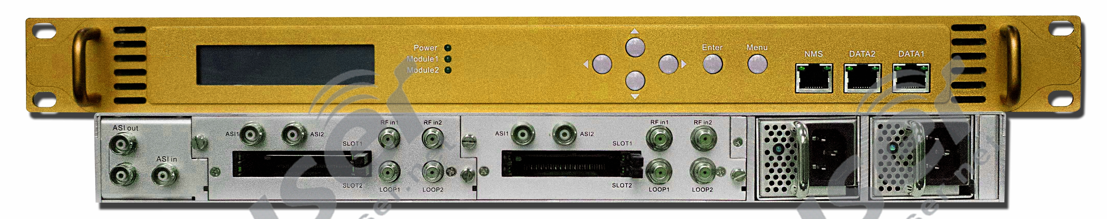
ਕਿਵੇਂ ਕਰਦਾ ਹੈ ਬ੍ਰੌਡਕਾਸਟ ਸੈਟੇਲਾਈਟ ਰਿਸੀਵਰ ਕੰਮ ਕਰਨ?
ਸੈਟੇਲਾਈਟ ਰਿਸੀਵਰ ਦੀ ਵਰਤੋਂ ਸੈਟੇਲਾਈਟ ਆਡੀਓ ਪ੍ਰੋਗਰਾਮ ਨੂੰ ਪ੍ਰਾਪਤ ਕਰਨ ਅਤੇ ਇਸ ਵਿੱਚ ਇਨਪੁਟ ਕਰਨ ਲਈ ਕੀਤੀ ਜਾਂਦੀ ਹੈ ਐਫਐਮ ਪ੍ਰਸਾਰਣ ਟ੍ਰਾਂਸਮੀਟਰ. ਅਤੇ ਰੈਕ ਰੂਮ ਵਿੱਚ ਸਿਗਨਲ ਸਰੋਤ ਸੈਟੇਲਾਈਟ ਦੁਆਰਾ ਪ੍ਰਸਾਰਿਤ ਪ੍ਰੋਗਰਾਮ ਦੇ ਸਰੋਤ ਦੇ ਬਰਾਬਰ ਹੈ। ਸੈਟੇਲਾਈਟ ਟੀਵੀ ਟੀਵੀ ਪ੍ਰੋਗਰਾਮ ਦਾ ਇੱਕ ਰੂਪ ਹੈ। ਇਹ ਸੰਚਾਰ ਉਪਗ੍ਰਹਿ, ਰੇਡੀਓ ਸਿਗਨਲਾਂ, ਬਾਹਰੀ FMUSER ਦੇ ਨੈਟਵਰਕ ਰਾਹੀਂ ਗਲੋਬਲ ਟੀਵੀ ਨੂੰ ਇੱਕ ਵਾਇਰਲੈੱਸ ਸਿਗਨਲ ਪ੍ਰਸਾਰਿਤ ਕਰ ਸਕਦਾ ਹੈ। ਟ੍ਰਾਂਸਮੀਟਰ ਐਂਟੀਨਾ, ਅਤੇ ਪ੍ਰਸਾਰਣ ਕੇਂਦਰ। ਪ੍ਰੋਗਰਾਮ ਸਰੋਤ ਸੇਵਾ ਪ੍ਰਦਾਤਾ ਦੇ ਪ੍ਰਸਾਰਣ ਕੇਂਦਰ ਨੂੰ ਸਿਗਨਲ ਭੇਜਦਾ ਹੈ। ਸੈਟੇਲਾਈਟ ਟੀਵੀ ਰਿਸੀਵਰ ਇਹਨਾਂ ਪ੍ਰੋਗਰਾਮਾਂ ਨੂੰ ਪ੍ਰਾਪਤ ਕਰਨ ਅਤੇ ਡੀਕ੍ਰਿਪਟ ਕਰਨ ਲਈ ਉਪਕਰਣ ਹੈ।
ਸੈਟੇਲਾਈਟ ਰਿਸੀਵਰਾਂ ਦੀਆਂ ਚਾਰ ਆਮ ਕਿਸਮਾਂ ਹਨ
- HD ਰਿਸੀਵਰ
- ਆਮ ਰਿਸੀਵਰ
- ਰਿਕਾਰਡਰ ਦੇ ਨਾਲ ਡਿਜੀਟਲ ਰਿਸੀਵਰ
- ਐਨਕ੍ਰਿਪਟਡ ਚੈਨਲ ਰਿਸੀਵਰ
ਰੇ ਤੋਂ ਸੁਝਾਅ - ਸੈਟੇਲਾਈਟ ਟੀਵੀ ਇੱਕ ਵਿਸ਼ੇਸ਼ ਐਂਟੀਨਾ ਵਰਤਦਾ ਹੈ, ਜਿਸਨੂੰ ਆਮ ਤੌਰ 'ਤੇ ਏ ਕਿਹਾ ਜਾਂਦਾ ਹੈ ਸੈਟੇਲਾਈਟ ਐਂਟੀਨਾ.
ਇਸੇ ਬ੍ਰੌਡਕਾਸਟ ਸੈਟੇਲਾਈਟ ਰਿਸੀਵਰ ਮਹੱਤਵਪੂਰਨ ਹੈ?
ਉਹਨਾਂ ਵਿੱਚੋਂ ਜ਼ਿਆਦਾਤਰ ਮੁਫਤ ਸੈਟੇਲਾਈਟ ਪ੍ਰੋਗਰਾਮਾਂ ਨੂੰ ਰੀਲੇਅ ਕਰਨ ਲਈ ਵਰਤੇ ਜਾਂਦੇ ਹਨ ਕਿਉਂਕਿ ਉਹਨਾਂ ਦੇ ਆਪਣੇ ਪ੍ਰੋਗਰਾਮਾਂ ਨੂੰ ਪ੍ਰਸਾਰਿਤ ਕਰਨ ਲਈ ਸੈਟੇਲਾਈਟ ਕਿਰਾਏ 'ਤੇ ਲੈਣਾ ਬਹੁਤ ਮਹਿੰਗਾ ਹੁੰਦਾ ਹੈ, ਜਿਵੇਂ ਕਿ FmuserRay ਖੋਜ ਕਰਦਾ ਹੈ, ਉਪਯੋਗਤਾ ਮਾਡਲ ਇੱਕ ਆਡੀਓ ਫ੍ਰੀਕੁਐਂਸੀ ਐਂਪਲੀਫਾਇਰ ਨਾਲ ਸਬੰਧਤ ਹੈ। ਸਰਕਟ, ਇੱਕ ਸਿੰਗਲ-ਪੜਾਅ ਦੀ ਪਛਾਣ ਅਤੇ ਡੀਮੋਡੂਲੇਸ਼ਨ ਸਰਕਟ, ਇੱਕ ਆਡੀਓ ਫ੍ਰੀਕੁਐਂਸੀ ਐਂਪਲੀਫਾਇਰ ਕੰਟਰੋਲ ਸਰਕਟ, ਅਤੇ ਇੱਕ ਮਲਟੀ-ਫੇਜ਼ ਪਛਾਣ ਅਤੇ ਡੀਮੋਡੂਲੇਸ਼ਨ ਸਰਕਟ। ਇੱਕ ਕੇਬਲ ਪ੍ਰਸਾਰਣ ਸਿਗਨਲ ਸਰੋਤ fmuser.-net ਦੁਆਰਾ ਆਡੀਓ ਮੋਡਿਊਲੇਸ਼ਨ ਸਿਗਨਲ ਅਤੇ ਪ੍ਰਬੰਧਨ ਕੋਡ ਮੋਡੂਲੇਸ਼ਨ ਸਿਗਨਲ fmuser.-net ਇਨਪੁਟ ਨੂੰ ਡੀਮੋਡਿਊਲ ਕਰਨ ਤੋਂ ਬਾਅਦ, ਇੱਕ ਚੈਨਲ ਇੱਕ ਪ੍ਰਬੰਧਨ ਕੋਡ ਨੂੰ ਆਊਟਪੁੱਟ ਕਰਦਾ ਹੈ, ਇੱਕ ਚੈਨਲ ਮਾਈਕ੍ਰੋਪ੍ਰੋਸੈਸਰ ਦੁਆਰਾ ਇੱਕ ਕੰਟਰੋਲ ਕੋਡ ਨੂੰ ਆਉਟਪੁੱਟ ਕਰਦਾ ਹੈ, ਦੂਜਾ ਚੈਨਲ ਇੱਕ ਆਡੀਓ ਆਉਟਪੁੱਟ ਕਰਦਾ ਹੈ ਸਿਗਨਲ, ਅਤੇ ਆਉਟਪੁੱਟ ਕੰਟਰੋਲ ਕੋਡ ਆਡੀਓ ਸਿਗਨਲ ਦੀ ਚੋਣ ਨੂੰ ਨਿਯੰਤਰਿਤ ਕਰਦਾ ਹੈ। ਰਿਸੀਵਰ ਦੇ ਕਾਰਜਾਤਮਕ ਨਿਯੰਤਰਣ ਅਤੇ ਪ੍ਰਬੰਧਨ ਨੂੰ ਮਹਿਸੂਸ ਕਰੋ, ਤਾਂ ਜੋ ਕੇਬਲ ਆਡੀਓ ਪ੍ਰਸਾਰਣ ਉੱਚ-ਗੁਣਵੱਤਾ, ਮਲਟੀ-ਚੈਨਲ, ਮਲਟੀ-ਫੰਕਸ਼ਨਲ ਸੇਵਾਵਾਂ ਪ੍ਰਾਪਤ ਕਰ ਸਕੇ।![]()
![]()
ਰੇ ਤੋਂ ਸੁਝਾਅ - ਸੈਟੇਲਾਈਟ ਆਡੀਓ ਰਿਸੀਵਰ ਖਾਸ ਤੌਰ 'ਤੇ ਸੈਟੇਲਾਈਟ ਰਾਹੀਂ ਆਡੀਓ ਪ੍ਰੋਗਰਾਮਾਂ ਨੂੰ ਵੰਡਣ ਲਈ ਤਿਆਰ ਕੀਤਾ ਗਿਆ ਹੈ ਰੇਡੀਓ ਨੈੱਟਵਰਕ, ਜੋ ਕਿ ਰੇਡੀਓ ਡਿਸਟ੍ਰੀਬਿਊਸ਼ਨ ਐਪਲੀਕੇਸ਼ਨ ਦਾ ਸਭ ਤੋਂ ਮਹੱਤਵਪੂਰਨ ਹਿੱਸਾ ਹੈ
2. ਸਟੀਰੀਓ ਆਡੀਓ ਸਵਿੱਚਰ
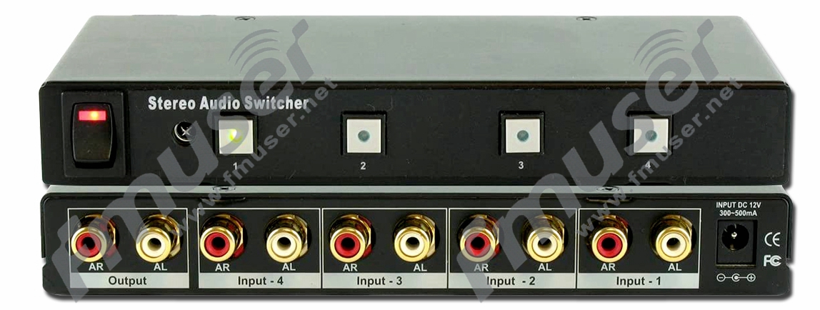
ਕਿਵੇਂ ਕਰਦਾ ਹੈ ਸਟੀਰੀਓ ਆਡੀਓ ਸਵਿੱਚਰ ਕੰਮ ਕਰਨ?
ਆਡੀਓ ਸਵਿੱਚਰ ਦੀ ਵਰਤੋਂ ਹਰ ਚੈਨਲ ਦੀ ਆਡੀਓ ਸਥਿਤੀ ਨੂੰ ਸਰਕੂਲਰ ਤੌਰ 'ਤੇ ਖੋਜਣ ਲਈ ਕੀਤੀ ਜਾਂਦੀ ਹੈ। ਸਵਿਚ ਕਰਨ ਵੇਲੇ, ਆਟੋਮੈਟਿਕ ਛੱਡਣ ਲਈ ਕੋਈ ਆਡੀਓ ਚੈਨਲ ਨਹੀਂ ਹੁੰਦਾ ਹੈ fmuser.-net ਅਤੇ ਸਵਿਚਿੰਗ ਦੇਰੀ ਦਾ ਸਮਾਂ ਵਿਕਲਪਿਕ ਹੈ। ਉਪਭੋਗਤਾ ਆਪਣੀਆਂ ਜ਼ਰੂਰਤਾਂ ਦੇ ਅਨੁਸਾਰ ਫਰੰਟ ਪੈਨਲ 'ਤੇ ਸਵਿਚਿੰਗ ਦੇਰੀ ਸਮੇਂ ਦੀਆਂ ਵੱਖ-ਵੱਖ ਲੰਬਾਈਆਂ ਨੂੰ ਸੈੱਟ ਕਰ ਸਕਦੇ ਹਨ, ਜੋ ਆਡੀਓ ਦੇ ਸੁਰੱਖਿਅਤ ਪ੍ਰਸਾਰਣ ਲਈ ਇੱਕ ਪ੍ਰਭਾਵਸ਼ਾਲੀ ਗਾਰੰਟੀ ਪ੍ਰਦਾਨ ਕਰਦਾ ਹੈ। ਆਡੀਓ ਸਵਿੱਚਰ ਇੱਕ ਮਲਟੀ-ਚੈਨਲ ਆਡੀਓ ਇੰਪੁੱਟ ਸਿਗਨਲ ਨੂੰ ਆਉਟਪੁੱਟ ਪੋਰਟ ਵਿੱਚ ਪ੍ਰਸਾਰਿਤ ਕਰ ਸਕਦਾ ਹੈ। ਮਲਟੀ-ਚੈਨਲ ਇਨਪੁਟ ਸਿਗਨਲ ਦੇ ਮਾਮਲੇ ਵਿੱਚ, ਇਹ ਕਿਸੇ ਵੀ ਇੰਪੁੱਟ ਸਿਗਨਲ ਨੂੰ ਆਉਟਪੁੱਟ ਪੋਰਟ ਵਿੱਚ ਬਦਲ ਸਕਦਾ ਹੈ।![]()
fmuser-ray ਤੋਂ ਸੁਝਾਅ - ਆਮ ਤੌਰ 'ਤੇ, ਆਡੀਓ ਸਵਿੱਚਰ 1 ~ 16 ਇਨਪੁਟ ਅਤੇ 1 ~ 16 ਆਉਟਪੁੱਟ ਦੀ ਕਿਸੇ ਵੀ ਸਵਿਚਿੰਗ ਨੂੰ ਪੂਰਾ ਕਰ ਸਕਦਾ ਹੈ। ਇਸ ਵਿਚ ਏ ਇਨਫਰਾਰੈੱਡ ਰਿਮੋਟ ਕੰਟਰੋਲ ਫੰਕਸ਼ਨ ਅਤੇ RS232 ਟਰਮੀਨਲ ਸੰਚਾਰ ਕੰਟਰੋਲ ਫੰਕਸ਼ਨ। ਇਹ RS485 ਬੱਸ ਇੰਟਰਫੇਸ ਨੂੰ ਪਹਿਲਾਂ ਤੋਂ ਜੋੜ ਸਕਦਾ ਹੈ, ਅਤੇ ਉਪਭੋਗਤਾ ਪ੍ਰਦਰਸ਼ਨ ਪ੍ਰਕਿਰਿਆ ਵਿੱਚ ਸਿਗਨਲ ਸਵਿਚਿੰਗ ਨੂੰ ਆਸਾਨੀ ਨਾਲ ਪੂਰਾ ਕਰ ਸਕਦੇ ਹਨ।![]()
![]()
ਇਸੇ ਸਟੀਰੀਓ ਆਡੀਓ ਸਵਿੱਚਰ ਮਹੱਤਵਪੂਰਨ ਹੈ?
ਆਡੀਓ ਸਵਿੱਚਰ ਆਉਟਪੁੱਟ ਪੋਰਟ ਨੂੰ ਮਲਟੀਪਲ ਆਡੀਓ ਇੰਪੁੱਟ ਸਿਗਨਲ ਪ੍ਰਸਾਰਿਤ ਕਰ ਸਕਦਾ ਹੈ। ਮਲਟੀਪਲ ਇਨਪੁਟ ਸਿਗਨਲ ਦੇ ਮਾਮਲੇ ਵਿੱਚ, ਕਿਸੇ ਵੀ ਇੰਪੁੱਟ ਸਿਗਨਲ ਨੂੰ ਆਉਟਪੁੱਟ ਪੋਰਟ ਵਿੱਚ ਬਦਲਿਆ ਜਾ ਸਕਦਾ ਹੈ। ਇਹ ਐਨਾਲਾਗ ਅਤੇ ਡਿਜੀਟਲ ਆਡੀਓ ਸਵਿੱਚਰ (ਕੁਝ ਵੀਡੀਓ ਵਾਲੇ) ਤੁਹਾਨੂੰ ਖੱਬੇ ਅਤੇ ਸੱਜੇ ਐਨਾਲਾਗ ਅਤੇ/ਜਾਂ ਡਿਜੀਟਲ ਆਡੀਓ ਇਨਪੁਟਸ ਨੂੰ ਇੱਕ ਜਾਂ ਇੱਕ ਤੋਂ ਵੱਧ ਆਉਟਪੁੱਟ ਨਾਲ ਜੋੜਨ ਦੀ ਇਜਾਜ਼ਤ ਦਿੰਦੇ ਹਨ। FM ਉਪਭੋਗਤਾ ਤੋਂ ਸੁਝਾਅ - ਜਦੋਂ ਇਨਪੁਟ ਸੀਮਤ ਹੁੰਦਾ ਹੈ, ਤਾਂ ਉਹ ਕੇਬਲ ਨੂੰ ਡਿਸਕਨੈਕਟ ਕਰਨ ਅਤੇ ਮੁੜ ਕਨੈਕਟ ਕਰਨ ਦੀ ਬਜਾਏ ਸਧਾਰਨ ਸਵਿਚ ਕਰਨ ਦੀ ਇਜਾਜ਼ਤ ਦਿੰਦੇ ਹਨ। ਵੱਖ-ਵੱਖ ਉਦਯੋਗਾਂ ਦੀਆਂ ਜ਼ਰੂਰਤਾਂ ਦੇ ਅਨੁਸਾਰ, ਆਡੀਓ ਸਵਿੱਚਰ ਵਿੱਚ ਨਾ ਸਿਰਫ ਇੱਕ ਆਰਸੀਏ ਇੰਟਰਫੇਸ ਹੈ ਜੋ ਇੱਕ ਅਸੰਤੁਲਿਤ ਆਡੀਓ ਸਿਗਨਲ ਦਾ ਸਮਰਥਨ ਕਰਦਾ ਹੈ ਬਲਕਿ ਇੱਕ ਪੇਸ਼ੇਵਰ ਸੰਤੁਲਿਤ ਆਡੀਓ XLR ਇੰਟਰਫੇਸ ਵੀ ਹੈ। www.fmuser.-net ਆਡੀਓ ਸਵਿੱਚਰ ਇੱਕ ਉੱਚ-ਪ੍ਰਦਰਸ਼ਨ ਵਾਲਾ ਬੁੱਧੀਮਾਨ ਮੈਟਰਿਕਸ ਸਵਿੱਚ ਉਪਕਰਣ ਹੈ ਜੋ ਵਿਸ਼ੇਸ਼ ਤੌਰ 'ਤੇ ਆਡੀਓ ਸਿਗਨਲ ਡਿਸਪਲੇਅ ਸਵਿਚਿੰਗ fmuser.-net ਲਈ ਤਿਆਰ ਕੀਤਾ ਗਿਆ ਹੈ। ਸਟੀਰੀਓ ਆਡੀਓ ਸਵਿੱਚਰ ਨੂੰ ਵੌਇਸ ਇੰਜੀਨੀਅਰਿੰਗ, ਆਡੀਓ-ਵਿਜ਼ੂਅਲ ਟੀਚਿੰਗ, ਕਮਾਂਡ, ਅਤੇ ਕੰਟਰੋਲ ਸੈਂਟਰ, ਮਲਟੀਮੀਡੀਆ ਕਾਨਫਰੰਸ ਰੂਮ, ਅਤੇ ਆਡੀਓ ਸਿਗਨਲ ਸਵਿਚਿੰਗ ਨੂੰ ਪੂਰਾ ਕਰਨ ਲਈ ਹੋਰ ਮੌਕਿਆਂ ਲਈ ਵਿਆਪਕ ਤੌਰ 'ਤੇ ਵਰਤਿਆ ਜਾਂਦਾ ਹੈ।![]()
3. ਬ੍ਰੌਡਕਾਸਟ ਆਡੀਓ ਪ੍ਰੋਸੈਸਰ
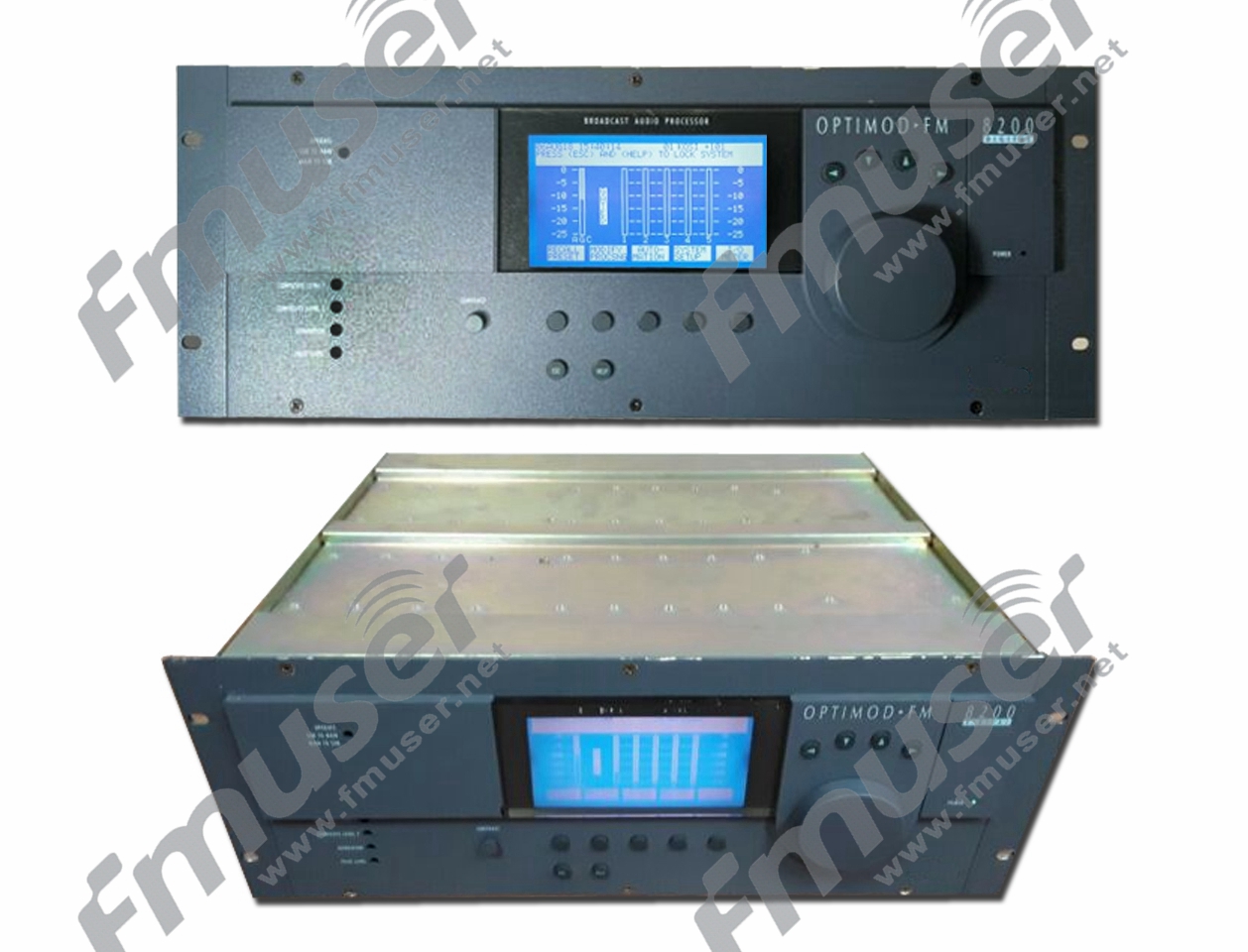
ਕਿਵੇਂ ਕਰਦਾ ਹੈ ਬਰਾਡਕਾਸਟ ਆਡੀਓ ਪ੍ਰੋਸੈਸਰ ਕੰਮ ਕਰਨ?
The ਆਡੀਓ ਪ੍ਰੋਸੈਸਰ ਸੈਟੇਲਾਈਟ ਰਿਸੀਵਰ ਤੋਂ ਪ੍ਰਾਪਤ ਆਡੀਓ ਸਿਗਨਲ ਦੀ ਪ੍ਰਕਿਰਿਆ ਕਰ ਸਕਦਾ ਹੈ। ਪ੍ਰਸਾਰਣ ਆਡੀਓ ਪ੍ਰੋਸੈਸਰ ਵਿਸ਼ੇਸ਼ ਮਲਟੀ-ਬੈਂਡ ਕੰਪ੍ਰੈਸ਼ਰ/ਲਿਮਿਟਰ ਸ਼ਾਮਲ ਹਨ। ਆਡੀਓ ਪ੍ਰੋਸੈਸਰ ਆਡੀਓ ਸਿਗਨਲਾਂ ਦੇ ਸੰਚਾਰਿਤ ਹੋਣ ਤੋਂ ਪਹਿਲਾਂ ਵਰਤੇ ਜਾਣ ਵਾਲੇ ਉਪਕਰਣਾਂ ਦਾ ਆਖਰੀ ਟੁਕੜਾ ਹੋਵੇਗਾ। ਇੱਕ ਆਡੀਓ ਪ੍ਰੋਸੈਸਰ, ਜਿਸਨੂੰ ਇੱਕ ਡਿਜੀਟਲ ਪ੍ਰੋਸੈਸਰ ਵੀ ਕਿਹਾ ਜਾਂਦਾ ਹੈ, ਇੱਕ ਬਹੁ-ਕਾਰਜਸ਼ੀਲ ਆਡੀਓ ਡਿਜੀਟਲ ਸਿਗਨਲ ਪ੍ਰੋਸੈਸਿੰਗ ਪ੍ਰਭਾਵ ਨੂੰ ਪ੍ਰਾਪਤ ਕਰਨ ਲਈ ਇੱਕ ਕਿਸਮ ਦਾ ਉਪਕਰਣ ਹੈ। ਐੱਫ.ਐੱਮuserray ਮੰਨਦਾ ਹੈ: ਬਹੁਤ ਸਾਰੇ ਵੱਡੇ ਇਲੈਕਟ੍ਰਾਨਿਕ ਯੰਤਰਾਂ ਦੀ ਵਰਤੋਂ ਕਰਦੇ ਸਮੇਂ ਅਸੀਂ ਅਕਸਰ ਆਡੀਓ ਪ੍ਰੋਸੈਸਿੰਗ ਡਿਵਾਈਸਾਂ ਦੀ ਵਰਤੋਂ ਕਰਦੇ ਹਾਂ। www-fmuser-net ਇਹ ਸੰਗੀਤ ਜਾਂ ਸਕੋਰ ਸੰਗੀਤ ਨੂੰ ਨਿਯੰਤਰਿਤ ਕਰਨ ਵਿੱਚ ਸਾਡੀ ਮਦਦ ਕਰ ਸਕਦਾ ਹੈ, ਇਸਨੂੰ ਵੱਖ-ਵੱਖ ਦ੍ਰਿਸ਼ਾਂ ਵਿੱਚ ਵੱਖੋ-ਵੱਖਰੇ ਧੁਨੀ ਪ੍ਰਭਾਵ ਪੈਦਾ ਕਰ ਸਕਦਾ ਹੈ, ਸੰਗੀਤ ਜਾਂ ਸਕੋਰ ਸੰਗੀਤ ਦੇ ਸਦਮੇ ਨੂੰ ਵਧਾ ਸਕਦਾ ਹੈ, ਅਤੇ ਇਸਦੇ ਨਾਲ ਹੀ, ਸੰਗੀਤ ਦੀ ਗੁਣਵੱਤਾ ਵਿੱਚ ਸੁਧਾਰ ਕਰਨ ਲਈ ਬਹੁਤ ਕੁਝ ਕੰਟਰੋਲ ਕਰਨ ਲਈ ਕਾਫ਼ੀ ਹੈ। ਸਾਈਟ 'ਤੇ ਆਡੀਓ ਫੰਕਸ਼ਨਾਂ ਦਾ। ਆਡੀਓ ਪ੍ਰੋਸੈਸਰ ਦੀ ਅੰਦਰੂਨੀ ਬਣਤਰ ਆਮ ਤੌਰ 'ਤੇ ਇਨਪੁਟ ਪਾਰਟਸ ਅਤੇ ਆਉਟਪੁੱਟ ਪਾਰਟਸ ਨਾਲ ਬਣੀ ਹੁੰਦੀ ਹੈ। ਇਸਦੇ ਅੰਦਰੂਨੀ ਫੰਕਸ਼ਨ ਵਧੇਰੇ ਸੰਪੂਰਨ ਹਨ, ਕੁਝ ਡਰੈਗ ਅਤੇ ਡ੍ਰੌਪ ਪ੍ਰੋਗਰਾਮਿੰਗ ਪ੍ਰੋਸੈਸਿੰਗ ਮੋਡੀਊਲ ਦੇ ਨਾਲ, ਜੋ ਉਪਭੋਗਤਾਵਾਂ ਦੁਆਰਾ ਸੁਤੰਤਰ ਤੌਰ 'ਤੇ ਬਣਾਏ ਜਾ ਸਕਦੇ ਹਨ, fmuser.-net.![]()
ਆਮ ਤੌਰ 'ਤੇ, ਇੱਕ ਡਿਜੀਟਲ ਪ੍ਰੋਸੈਸਰ ਦਾ ਅੰਦਰੂਨੀ ਆਰਕੀਟੈਕਚਰ ਆਮ ਤੌਰ 'ਤੇ ਇੱਕ ਇਨਪੁਟ ਪੋਰਟ ਅਤੇ ਇੱਕ ਆਉਟਪੁੱਟ ਹਿੱਸੇ ਨਾਲ ਬਣਿਆ ਹੁੰਦਾ ਹੈ। ਆਡੀਓ ਪ੍ਰੋਸੈਸਿੰਗ ਹਿੱਸੇ ਦੇ ਫੰਕਸ਼ਨ ਆਮ ਤੌਰ 'ਤੇ ਹੇਠਾਂ ਦਿੱਤੇ ਅਨੁਸਾਰ ਹੁੰਦੇ ਹਨ: ਇਨਪੁਟ ਹਿੱਸੇ ਵਿੱਚ ਆਮ ਤੌਰ 'ਤੇ ਇਨਪੁਟ ਗੇਨ ਕੰਟਰੋਲ (ਇਨਪੁਟ ਗੇਨ), ਇਨਪੁਟ ਸਮਾਨਤਾ (ਪੈਰਾਮੀਟਰ ਸਮਾਨਤਾ ਦੇ ਕਈ ਹਿੱਸੇ), ਇਨਪੁਟ EQ, ਅਤੇ ਇਸ ਤਰ੍ਹਾਂ, ਇੰਪੁੱਟ ਦੇਰੀ, ਇਨਪੁਟ ਪੋਲਰਿਟੀ, ਆਦਿ ਸ਼ਾਮਲ ਹੁੰਦੇ ਹਨ, fmuser.-net. ਆਉਟਪੁੱਟ ਹਿੱਸੇ ਵਿੱਚ ਆਮ ਤੌਰ 'ਤੇ ਕਈ ਆਮ ਫੰਕਸ਼ਨ ਹੁੰਦੇ ਹਨ, ਜਿਵੇਂ ਕਿ ਸਿਗਨਲ ਇਨਪੁਟ ਡਿਸਟ੍ਰੀਬਿਊਸ਼ਨ, ਰੂਟਿੰਗ (ਗੋਲ), ਉੱਚ ਪਾਸ ਫਿਲਟਰ (ਐਚਪੀਐਫ), ਲੋਅ ਪਾਸ ਫਿਲਟਰ (ਐਲਪੀਐਫ), ਬਰਾਬਰੀ (ਆਉਟਪੁੱਟ EQ), ਪੋਲਰਿਟੀ, ਲਾਭ, ਦੇਰੀ, ਸੀਮਾ ਸ਼ੁਰੂਆਤੀ ਪੱਧਰ ( ਸੀਮਾ)।![]()
ਆਮ ਆਡੀਓ ਪ੍ਰੋਸੈਸਰਾਂ ਨੂੰ 4 ਕਿਸਮਾਂ ਵਿੱਚ ਵੰਡਿਆ ਜਾ ਸਕਦਾ ਹੈ:
-
ਸਧਾਰਨ ਸਪੀਕਰ ਪ੍ਰੋਸੈਸਰ
ਇਹ ਸਿਗਨਲ ਪ੍ਰੋਸੈਸਿੰਗ ਲਈ ਐਨਾਲਾਗ ਪੈਰੀਫਿਰਲ ਉਪਕਰਣਾਂ ਦੀ ਬਜਾਏ ਮਿਕਸਰ ਨੂੰ ਪਾਵਰ ਐਂਪਲੀਫਾਇਰ ਨਾਲ ਜੋੜਨ ਲਈ ਵਰਤਿਆ ਜਾਂਦਾ ਹੈ।
-
8-ਇਨ 8-ਆਊਟ ਮਲਟੀ-ਫੰਕਸ਼ਨਲ ਡਿਜੀਟਲ ਆਡੀਓ ਪ੍ਰੋਸੈਸਰ
ਇਹ ਕਾਨਫਰੰਸ ਸਿਸਟਮ ਵਿੱਚ ਛੋਟੇ ਮਿਕਸਰ ਅਤੇ ਪੈਰੀਫਿਰਲ ਉਪਕਰਣਾਂ ਦੇ ਬਣੇ ਐਨਾਲਾਗ ਸਿਸਟਮ ਨੂੰ ਬਦਲ ਸਕਦਾ ਹੈ। ਇਸਦਾ ਇੱਕ ਨੈਟਵਰਕ ਇੰਟਰਫੇਸ ਹੈ ਅਤੇ ਪ੍ਰੋਗਰਾਮਿੰਗ ਅਤੇ ਔਨਲਾਈਨ ਰੀਅਲ-ਟਾਈਮ ਨਿਯੰਤਰਣ ਲਈ ਈਥਰਨੈੱਟ ਦੁਆਰਾ ਕੰਪਿਊਟਰ ਨਾਲ ਜੁੜਿਆ ਜਾ ਸਕਦਾ ਹੈ।
-
ਨੈੱਟਵਰਕ ਆਡੀਓ ਟਰਾਂਸਮਿਸ਼ਨ ਫੰਕਸ਼ਨ ਦੇ ਨਾਲ ਡਿਜੀਟਲ ਆਡੀਓ ਪ੍ਰੋਸੈਸਰ
ਇਹ ਉਪਰੋਕਤ ਦੋ ਫੰਕਸ਼ਨਾਂ ਦੇ ਸਮਾਨ ਹੈ, ਪਰ ਨੈਟਵਰਕ ਦਾ ਆਡੀਓ ਟ੍ਰਾਂਸਮਿਸ਼ਨ ਫੰਕਸ਼ਨ ਜੋੜਿਆ ਗਿਆ ਹੈ (ਕੋਬਰਾਨੈੱਟ ਆਮ ਤੌਰ 'ਤੇ ਸਮਰਥਿਤ ਹੈ), ਜੋ ਇੱਕ LAN ਵਿੱਚ ਇੱਕ ਦੂਜੇ ਨੂੰ ਆਡੀਓ ਡੇਟਾ ਪ੍ਰਸਾਰਿਤ ਕਰ ਸਕਦਾ ਹੈ।
-
ਪ੍ਰੋਸੈਸਿੰਗ ਮੈਟ੍ਰਿਕਸ
ਇਸ ਕਿਸਮ ਦਾ ਪ੍ਰੋਸੈਸਰ ਇੱਕ ਬਹੁਤ ਸ਼ਕਤੀਸ਼ਾਲੀ ਹੋਸਟ ਹੈ, ਜੋ ਆਮ ਤੌਰ 'ਤੇ ਵੱਡੇ ਪ੍ਰਸਾਰਣ ਪ੍ਰਣਾਲੀਆਂ ਜਾਂ ਕਾਨਫਰੰਸ ਸੈਂਟਰਾਂ ਵਿੱਚ ਵਰਤਿਆ ਜਾਂਦਾ ਹੈ। ਵੱਡੇ ਪ੍ਰੋਸੈਸਿੰਗ ਮੈਟ੍ਰਿਕਸ ਨੂੰ ਕੰਪਿਊਟਰ ਰੂਮ ਵਿੱਚ ਕੇਂਦਰੀਕ੍ਰਿਤ ਕੀਤਾ ਜਾਂਦਾ ਹੈ, ਅਤੇ ਸਾਰੇ ਕਮਰਿਆਂ ਦਾ ਪ੍ਰੋਸੈਸਿੰਗ ਕੰਟਰੋਲ ਮੁੱਖ ਕੰਪਿਊਟਰ ਰੂਮ ਵਿੱਚ ਮਸ਼ੀਨ ਦੁਆਰਾ ਪੂਰਾ ਕੀਤਾ ਜਾਂਦਾ ਹੈ। ਇਸ ਲਈ, fmuser.-net, ਭਾਵੇਂ ਇੱਕ ਜਾਂ ਵੱਧ ਕਮਰੇ ਵਰਤੇ ਗਏ ਹੋਣ, ਮੁੱਖ ਕੰਪਿਊਟਰ ਰੂਮ ਵਿੱਚ ਪ੍ਰੋਸੈਸਰ ਨੂੰ ਕਿਸੇ ਵੀ ਸਮੇਂ fmuser.-net ਨੂੰ ਚਾਲੂ ਕਰਨਾ ਚਾਹੀਦਾ ਹੈ। ਇਸ ਕਿਸਮ ਦਾ ਆਡੀਓ ਨੈੱਟਵਰਕ ਕੋਬਰਾਨੈੱਟ ਜਾਂ ਗੀਗਾਬਿਟ ਈਥਰਨੈੱਟ ਦੇ ਹੋਰ ਪ੍ਰੋਟੋਕੋਲ 'ਤੇ ਆਧਾਰਿਤ ਹੈ ਅਤੇ ਅਸਲ-ਸਮੇਂ ਦੇ ਪ੍ਰਸਾਰਣ ਅਤੇ ਨਿਯੰਤਰਣ ਦਾ ਸਮਰਥਨ ਕਰਦਾ ਹੈ।
ਇਸੇ ਬਰਾਡਕਾਸਟ ਆਡੀਓ ਪ੍ਰੋਸੈਸਰ ਮਹੱਤਵਪੂਰਨ ਹੈ?
ਸਰਲ ਪੱਧਰ 'ਤੇ, ਡੀਐਸਪੀ ਨੂੰ ਇੱਕ ਸੁੰਦਰ ਅਤੇ ਬਹੁਤ ਹੀ ਸਟੀਕ ਟੋਨ ਕੰਟਰੋਲ ਮੰਨਿਆ ਜਾ ਸਕਦਾ ਹੈ। ਜਦੋਂ ਤੁਸੀਂ ਜੋੜਦੇ ਹੋ ਪ੍ਰੋਸੈਸਰ ਰੀਅਲ-ਟਾਈਮ ਵਿਸ਼ਲੇਸ਼ਕ ਦੇ ਮਾਪ ਫੰਕਸ਼ਨ ਦੇ ਨਾਲ fmuser ਤੋਂ, ਆਡੀਓ ਸਿਸਟਮ ਦੇ ਟੋਨ ਸੰਤੁਲਨ ਅਤੇ ਸ਼ੁੱਧਤਾ ਨੂੰ ਸਹੀ ਢੰਗ ਨਾਲ ਸਿਖਲਾਈ ਪ੍ਰਾਪਤ ਤਕਨੀਸ਼ੀਅਨ ਦੁਆਰਾ ਬਹੁਤ ਸੁਧਾਰ ਕੀਤਾ ਜਾ ਸਕਦਾ ਹੈ। ਰਿਕਾਰਡਿੰਗਾਂ ਨੂੰ ਸੁਣਨ ਦੀ ਬਜਾਏ, ਮਨੁੱਖਾਂ ਦੀ ਆਵਾਜ਼ ਅਤੇ ਸੰਗੀਤਕ ਸਾਜ਼ਾਂ ਦੀ ਆਵਾਜ਼ ਮੌਕੇ 'ਤੇ ਪ੍ਰਦਰਸ਼ਨ ਕਰਨ ਵਰਗੀ ਲੱਗਦੀ ਹੈ। ਮਾਹਰ ਤਕਨੀਸ਼ੀਅਨ ਤੁਹਾਡੇ ਸਾਊਂਡ ਸਿਸਟਮ ਦੀਆਂ ਸਟੇਜਿੰਗ ਅਤੇ ਇਮੇਜਿੰਗ ਵਿਸ਼ੇਸ਼ਤਾਵਾਂ ਨੂੰ ਬਿਹਤਰ ਬਣਾਉਣ ਲਈ ਸਟੀਰੀਓ ਬਰਾਬਰੀ ਦੀ ਵਰਤੋਂ ਕਰ ਸਕਦੇ ਹਨ, ਜੋ ਸੁਣਨ ਦੇ ਅਨੁਭਵ ਦੀ ਪ੍ਰਮਾਣਿਕਤਾ ਨੂੰ ਹੋਰ ਬਿਹਤਰ ਬਣਾਉਣ ਵਿੱਚ ਮਦਦ ਕਰ ਸਕਦੇ ਹਨ।
ਐਫਐਮ ਆਡੀਓ ਪ੍ਰੋਸੈਸਿੰਗ ਤਕਨਾਲੋਜੀ ਇਸ ਵਿਚਾਰ 'ਤੇ ਅਧਾਰਤ ਹੈ ਕਿ ਇਹ ਦਰਸ਼ਕਾਂ ਨੂੰ ਕਿਸੇ ਵੀ ਤਬਦੀਲੀ ਦਾ ਭੁਲੇਖਾ ਪਾਉਂਦੇ ਹੋਏ ਇਸ ਲਾਭ ਨੂੰ ਮਹਿਸੂਸ ਕਰ ਸਕਦੀ ਹੈ। ਸਫਲ ਆਡੀਓ ਪ੍ਰੋਸੈਸਿੰਗ ਇੱਕ ਕੁਦਰਤੀ ਅਤੇ ਯਥਾਰਥਵਾਦੀ ਵਿਅਕਤੀਗਤ ਨਤੀਜਾ ਪੇਸ਼ ਕਰਦੇ ਹੋਏ ਲੋੜੀਂਦੇ ਬਿਜਲਈ ਸੋਧਾਂ ਕਰਦੀ ਹੈ।
![]()
U ਉਦਾਹਰਨ ਲਈ, ਪ੍ਰੋਸੈਸਿੰਗ ਦੇ ਕਾਰਨ ਗਤੀਸ਼ੀਲ ਰੇਂਜ ਦੀ ਕਮੀ ਰੌਲੇ-ਰੱਪੇ ਵਾਲੇ ਵਾਤਾਵਰਣਾਂ (ਖਾਸ ਕਰਕੇ ਕਾਰਾਂ) ਵਿੱਚ ਸੁਣਨਾ ਵਧੇਰੇ ਮੁਸ਼ਕਲ ਬਣਾਉਂਦੀ ਹੈ। ਇੱਕ ਵਿਸ਼ਾਲ ਗਤੀਸ਼ੀਲ ਰੇਂਜ ਵਾਲੇ ਸੰਗੀਤ ਵਿੱਚ, ਨਰਮ ਸੰਗੀਤ ਅਕਸਰ ਬੈਕਗ੍ਰਾਉਂਡ ਸ਼ੋਰ ਦੇ ਪ੍ਰਭਾਵ ਅਧੀਨ ਪੂਰੀ ਤਰ੍ਹਾਂ ਅਲੋਪ ਹੋ ਜਾਂਦਾ ਹੈ। ਬਹੁਤ ਘੱਟ ਸਰੋਤੇ ਪੂਰੀ ਤਰ੍ਹਾਂ ਸ਼ਾਂਤ ਮਾਹੌਲ ਵਿੱਚ ਸੰਗੀਤ ਸੁਣਦੇ ਹਨ। ਜੇਕਰ ਤੁਸੀਂ ਵੌਲਯੂਮ ਵਧਾਉਂਦੇ ਹੋ, ਤਾਂ ਵੱਡੇ ਚੈਨਲ ਬਾਅਦ ਵਿੱਚ ਅਸੁਵਿਧਾਜਨਕ ਹੋ ਸਕਦੇ ਹਨ। ਕਾਰਾਂ ਵਿੱਚ, ਗਤੀਸ਼ੀਲ ਰੇਂਜ ਇਹਨਾਂ ਸਮੱਸਿਆਵਾਂ ਨੂੰ ਪੈਦਾ ਕੀਤੇ ਬਿਨਾਂ 20 dB ਤੋਂ ਵੱਧ ਨਹੀਂ ਹੋ ਸਕਦੀ। ਸਮਰੱਥ ਆਡੀਓ ਪ੍ਰੋਸੈਸਿੰਗ ਬਿਨਾਂ ਕਿਸੇ ਮਾੜੇ ਪ੍ਰਭਾਵਾਂ ਦੇ ਪ੍ਰੋਗਰਾਮ ਦੀ ਗਤੀਸ਼ੀਲ ਰੇਂਜ ਨੂੰ ਘਟਾ ਸਕਦੀ ਹੈ।![]()
S ਇਸ ਤੋਂ ਇਲਾਵਾ, ਪ੍ਰਸਾਰਣ ਪ੍ਰੋਗਰਾਮ ਸਮੱਗਰੀ ਆਮ ਤੌਰ 'ਤੇ ਤੇਜ਼ੀ ਨਾਲ ਬਦਲ ਰਹੇ ਸਰੋਤਾਂ ਦੀ ਇੱਕ ਕਿਸਮ ਤੋਂ ਹੁੰਦੀ ਹੈ, ਜਿਨ੍ਹਾਂ ਵਿੱਚੋਂ ਜ਼ਿਆਦਾਤਰ ਹੋਰ ਸਪੈਕਟ੍ਰਮ ਸੰਤੁਲਨ ਨੂੰ ਧਿਆਨ ਵਿੱਚ ਰੱਖੇ ਬਿਨਾਂ ਬਣਾਏ ਜਾਂਦੇ ਹਨ। ਜੇਕਰ ਮਲਟੀ-ਬੈਂਡ ਸੀਮਾ ਸਹੀ ਢੰਗ ਨਾਲ ਵਰਤੀ ਜਾਂਦੀ ਹੈ, ਤਾਂ ਸਰੋਤਾਂ ਵਿਚਕਾਰ ਦਖਲ ਆਪਣੇ ਆਪ ਹੀ ਇਕਸਾਰ ਹੋ ਸਕਦਾ ਹੈ। ਐਫਐਮ-ਉਪਭੋਗਤਾ-ਰੇ ਜਾਣਦਾ ਹੈ ਕਿ ਜਿਸ ਤਰ੍ਹਾਂ ਲੰਬੀਆਂ ਫਿਲਮਾਂ ਇਕਸਾਰ ਦਿੱਖ ਨੂੰ ਬਣਾਈ ਰੱਖਣ ਲਈ ਬਣਾਈਆਂ ਜਾਂਦੀਆਂ ਹਨ, ਮਲਟੀ-ਬੈਂਡ ਪਾਬੰਦੀਆਂ ਅਤੇ ਇਕਸਾਰਤਾ ਉਹਨਾਂ ਸਟੇਸ਼ਨਾਂ ਲਈ ਜ਼ਰੂਰੀ ਹਨ ਜੋ ਵਿਲੱਖਣ ਆਡੀਓ ਦਸਤਖਤ ਅਤੇ ਮਜ਼ਬੂਤ ਸਕਾਰਾਤਮਕ ਸ਼ਖਸੀਅਤਾਂ ਨੂੰ ਵਿਕਸਤ ਕਰਨਾ ਚਾਹੁੰਦੇ ਹਨ। ਦਿਨ ਦੇ ਅੰਤ 'ਤੇ, ਇਹ ਸਭ ਦਰਸ਼ਕਾਂ ਦੇ ਅਨੁਭਵ ਨਾਲ ਕਰਨਾ ਹੈ.
E ਇਸ ਤੋਂ ਇਲਾਵਾ, ਜ਼ਿਆਦਾਤਰ ਦੇਸ਼ਾਂ ਵਿੱਚ ਓਵਰ ਮੋਡਿਊਲੇਸ਼ਨ ਲਈ ਬਹੁਤ ਘੱਟ ਸਹਿਣਸ਼ੀਲਤਾ ਹੈ, ਇਸਲਈ ਨਿਯੰਤ੍ਰਿਤ ਜਨਤਕ ਤਰੰਗਾਂ ਨੂੰ ਭੇਜੇ ਜਾਣ ਵਾਲੇ ਸਿਗਨਲਾਂ ਲਈ ਸਿਖਰ ਸੀਮਾਵਾਂ ਲਾਗੂ ਕੀਤੀਆਂ ਜਾਣੀਆਂ ਚਾਹੀਦੀਆਂ ਹਨ।
R ਪ੍ਰੋਸੈਸਰ ਦੀ ਕਾਰਗੁਜ਼ਾਰੀ ਦਾ ਨਿਰਣਾ ਇੱਕ ਦਿੱਤੇ ਫਾਰਮੈਟ ਵਿੱਚ ਵਰਤੇ ਗਏ ਕਈ ਵੱਖ-ਵੱਖ ਕਿਸਮਾਂ ਦੇ ਪ੍ਰੋਗਰਾਮ ਡੇਟਾ ਦੇ ਅਧਾਰ ਤੇ ਕੀਤਾ ਜਾਣਾ ਚਾਹੀਦਾ ਹੈ, ਅਤੇ ਅੰਤ ਵਿੱਚ, ਪ੍ਰੋਸੈਸਰ ਨੂੰ ਦਿੱਤੇ ਪ੍ਰਸਾਰਕ ਦੇ ਨਿਸ਼ਾਨਾ ਦਰਸ਼ਕਾਂ ਨੂੰ ਆਕਰਸ਼ਿਤ ਕਰਨ ਅਤੇ ਬਣਾਈ ਰੱਖਣ ਦੀ ਯੋਗਤਾ ਦੇ ਅਧਾਰ ਤੇ ਨਿਰਣਾ ਕੀਤਾ ਜਾਣਾ ਚਾਹੀਦਾ ਹੈ। ਰੇ ਕਹਿੰਦਾ ਹੈ, ਲੰਬੇ ਸਮੇਂ ਤੱਕ ਸੁਣਨਾ ਅਟੱਲ ਹੈ।![]()
ਸੰਖੇਪ ਵਿੱਚ, ਡਿਜੀਟਲ ਆਡੀਓ ਪ੍ਰੋਸੈਸਰਾਂ ਦੀ ਵਰਤੋਂ ਕਰਨ ਦੇ ਫਾਇਦੇ ਹਨ:
-
ਆਡੀਓ ਵਿੱਚ ਸਮਾਨਤਾ ਨੂੰ ਹਟਾਉਣਾ
ਇਹ ਤੁਹਾਡੇ ਸੰਗੀਤ ਵਿੱਚ ਜੋੜਿਆ ਗਿਆ ਸੰਤੁਲਨ ਹਟਾ ਸਕਦਾ ਹੈ। ਰੇ ਕਹਿੰਦੇ ਹਨ, ਆਟੋਮੇਕਰਾਂ ਨੂੰ ਕਾਰਾਂ ਬਣਾਉਣ ਵਿੱਚ ਇੱਕ ਪੈਸਾ ਖਰਚ ਕਰਨਾ ਪੈਂਦਾ ਹੈ, ਇਸਲਈ ਉਹ ਉੱਚ-ਗੁਣਵੱਤਾ ਵਾਲੇ ਸਪੀਕਰਾਂ ਦੀ ਵਰਤੋਂ ਨਹੀਂ ਕਰਦੇ, ਉਹ ਸਸਤੇ ਸਪੀਕਰਾਂ ਦੀ ਵਰਤੋਂ ਕਰਦੇ ਹਨ ਅਤੇ ਉਹਨਾਂ ਨੂੰ ਵਧੀਆ ਆਵਾਜ਼ ਦੇਣ ਲਈ ਬਰਾਬਰੀ ਜੋੜਦੇ ਹਨ। ਜਦੋਂ ਤੁਸੀਂ ਅੱਪਗ੍ਰੇਡ ਕੀਤੇ ਸਪੀਕਰਾਂ ਨੂੰ ਜੋੜਦੇ ਹੋ, ਤਾਂ ਇਹ "ਡਿਸਕਲਰ ਧੁਨੀ" ਨੂੰ ਸੰਤੁਲਿਤ ਕਰਦਾ ਹੈ, ਜੋ ਤੁਹਾਡੇ ਦੁਆਰਾ ਸੁਣਾਈ ਜਾਣ ਵਾਲੀ ਆਵਾਜ਼ ਨੂੰ ਘਟਾਉਂਦਾ ਹੈ।
-
ਤੁਹਾਡੇ ਆਡੀਓ ਦਾ ਸਾਰ
ਬਹੁਤ ਸਾਰੇ ਉੱਨਤ ਫੈਕਟਰੀ ਆਡੀਓ ਸਿਸਟਮ ਸੰਗੀਤ ਸਿਗਨਲਾਂ ਨੂੰ ਵੱਖ-ਵੱਖ ਸਪੀਕਰ ਆਕਾਰਾਂ ਵਿੱਚ ਵੰਡਦੇ ਹਨ। ਕਿਉਂਕਿ ਤੁਸੀਂ ਚਾਹੁੰਦੇ ਹੋ ਕਿ ਨਵੇਂ ਸਪੀਕਰ ਵਧੀਆ ਪ੍ਰਦਰਸ਼ਨ 'ਤੇ ਕੰਮ ਕਰਨ, ਪ੍ਰੋਸੈਸਰ ਸਿਗਨਲਾਂ ਨੂੰ ਇੱਕ ਸਿੰਗਲ ਪੂਰੀ ਬਾਰੰਬਾਰਤਾ ਚੈਨਲ ਵਿੱਚ ਜੋੜਦਾ ਹੈ। ਹੁਣ, ਤੁਹਾਡਾ ਇੰਸਟੌਲਰ ਸੰਗੀਤ ਦੀ ਬਾਰੰਬਾਰਤਾ ਦੀ ਚੋਣ ਕਰ ਸਕਦਾ ਹੈ ਜੋ ਉਹਨਾਂ ਲਈ ਸਭ ਤੋਂ ਵਧੀਆ ਹੈ, ਰੇ ਕਹਿੰਦਾ ਹੈ।
-
ਸੁਣਨ ਦੇ ਅਨੁਭਵ ਨੂੰ ਵਧਾਉਣਾ
ਤੁਹਾਡੇ ਸੰਗੀਤ ਵਿੱਚ ਡਿਜੀਟਲ ਲੇਟੈਂਸੀ ਸ਼ਾਮਲ ਕੀਤੀ ਗਈ ਹੈ। ਕੀ ਤੁਸੀਂ ਕਦੇ ਦੇਖਿਆ ਹੈ ਕਿ ਤੁਹਾਡੀ ਆਵਾਜ਼ ਤੁਹਾਡੇ ਸਭ ਤੋਂ ਨੇੜੇ ਦੇ ਦਰਵਾਜ਼ੇ ਤੋਂ ਆਈ ਜਾਪਦੀ ਹੈ? ਪ੍ਰੋਸੈਸਰ ਸਾਨੂੰ ਹਰੇਕ ਸਪੀਕਰ ਦੀ ਆਵਾਜ਼ ਦੇ ਆਉਣ ਵਿੱਚ ਦੇਰੀ ਕਰਨ ਦੀ ਇਜਾਜ਼ਤ ਦਿੰਦਾ ਹੈ। ਹੁਣ, ਇਹ ਸਭ ਇੱਕੋ ਸਮੇਂ ਤੁਹਾਡੇ ਕੰਨਾਂ ਤੱਕ ਪਹੁੰਚ ਰਿਹਾ ਹੈ। ਇਹ ਤੁਹਾਡੀ ਅਵਾਜ਼ ਨੂੰ ਤੁਹਾਡੇ ਸਾਹਮਣੇ ਪ੍ਰਗਟ ਹੋਣ ਦੇਵੇਗਾ, ਸਟੇਜ ਅਤੇ ਚਿੱਤਰ ਪ੍ਰਭਾਵਾਂ ਦੇ ਨਾਲ ਇੰਟੀਮੇਟ ਜੈਜ਼ ਕੰਸਰਟ ਜਾਂ ਐਕੋਸਟਿਕ ਪ੍ਰਦਰਸ਼ਨ fmuser.-net ਨਾਲ ਤੁਲਨਾ ਕੀਤੀ ਜਾ ਸਕਦੀ ਹੈ।
-
ਧੁਨੀ ਗੁਣਵੱਤਾ ਅਤੇ ਆਉਟਪੁੱਟ ਗੁਣਵੱਤਾ ਵਿੱਚ ਸੁਧਾਰ
ਧਿਆਨ ਨਾਲ ਤਿਆਰ ਕੀਤਾ ਗਿਆ ਸਮਤੋਲ ਸਾਨੂੰ ਤੁਹਾਡੇ ਨਵੇਂ ਸਿਸਟਮ ਵਿੱਚ ਹਰੇਕ ਸਪੀਕਰ ਦੀ ਆਵਾਜ਼ ਦੀ ਗੁਣਵੱਤਾ ਅਤੇ ਆਉਟਪੁੱਟ ਨੂੰ ਵੱਧ ਤੋਂ ਵੱਧ ਕਰਨ ਲਈ ਵਿਅਕਤੀਗਤ ਤੌਰ 'ਤੇ ਵਧੀਆ-ਟਿਊਨ ਕਰਨ ਦੇ ਯੋਗ ਬਣਾਉਂਦਾ ਹੈ। ਸੰਖੇਪ ਵਿੱਚ, ਅਸੀਂ ਤੁਹਾਨੂੰ ਬਸ ਦੱਸ ਸਕਦੇ ਹਾਂ ਕਿ ਇੱਕ ਧਿਆਨ ਨਾਲ ਡਿਜ਼ਾਈਨ ਕੀਤਾ ਗਿਆ, ਧਿਆਨ ਨਾਲ ਬਣਾਇਆ ਗਿਆ ਪ੍ਰਸਾਰਣ ਸਿਸਟਮ ਅਤੇ ਸਹੀ ਢੰਗ ਨਾਲ ਐਡਜਸਟ ਕੀਤਾ ਗਿਆ ਪ੍ਰੋਸੈਸਰ ਲਗਭਗ 100% ਜਾਂ ਉੱਚੀ ਆਵਾਜ਼ ਦੀ ਗੁਣਵੱਤਾ ਵਿੱਚ ਸੁਧਾਰ ਲਿਆ ਸਕਦਾ ਹੈ।
4. ਰੈਕ AC ਪਾਵਰ ਕੰਡੀਸ਼ਨਰ
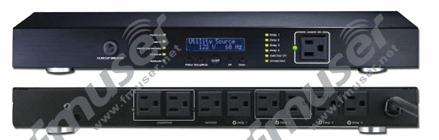
ਕਿਵੇਂ ਕਰਦਾ ਹੈ ਰੈਕ AC ਪਾਵਰ ਕੰਡੀਸ਼ਨਰ ਕੰਮ ਕਰਨ?
ਪਾਵਰ ਕੰਡੀਸ਼ਨਰ, ਜਿਸਨੂੰ ਲਾਈਨ ਕੰਡੀਸ਼ਨਰ ਵੀ ਕਿਹਾ ਜਾਂਦਾ ਹੈ, ਉਪਕਰਨਾਂ ਨੂੰ ਵਾਧੇ ਤੋਂ ਬਚਾ ਸਕਦਾ ਹੈ। ਇਸਦੀ ਵਰਤੋਂ ਵੋਲਟੇਜ ਦੇ ਉਤਰਾਅ-ਚੜ੍ਹਾਅ ਜਿਵੇਂ ਕਿ ਸਪਾਈਕਸ, ਟਰਾਂਜਿਐਂਟਸ ਅਤੇ ਬਿਜਲਈ ਸ਼ੋਰ ਨੂੰ ਖਤਮ ਕਰਕੇ ਸੰਵੇਦਨਸ਼ੀਲ ਲੋਡਾਂ ਦੀ ਰੱਖਿਆ ਕਰਨ ਲਈ ਕੀਤੀ ਜਾਂਦੀ ਹੈ। ਰੇਅ ਕਹਿੰਦਾ ਹੈ ਕਿ ਪਾਵਰ ਕੰਡੀਸ਼ਨਰ ਵੋਲਟੇਜ ਦੇ ਉਤਰਾਅ-ਚੜ੍ਹਾਅ ਅਤੇ ਰੇਡੀਓ ਅਤੇ ਇਲੈਕਟ੍ਰੋਮੈਗਨੈਟਿਕ ਦਖਲਅੰਦਾਜ਼ੀ fmuser.-net ਨੂੰ ਖਤਮ ਕਰਨ ਲਈ ਸਾਕਟ ਅਤੇ ਸਿਸਟਮ ਦੇ ਵਿਚਕਾਰ ਇੱਕ ਬਫਰ ਵਜੋਂ ਕੰਮ ਕਰਦਾ ਹੈ, ਜੋ ਕਿ ਸਿਸਟਮ ਦੀ ਕਾਰਗੁਜ਼ਾਰੀ ਨੂੰ ਪ੍ਰਭਾਵਿਤ ਕਰ ਸਕਦਾ ਹੈ। ਇੱਕ ਪਾਵਰ ਕੰਡੀਸ਼ਨਰ ਅਕਸਰ ਉਦਯੋਗਿਕ ਉਤਪਾਦਨ ਅਤੇ ਪ੍ਰਯੋਗਸ਼ਾਲਾ ਖੋਜ ਵਿੱਚ ਵਰਤਿਆ ਜਾਂਦਾ ਹੈ, ਅਤੇ ਇਹ ਘਰੇਲੂ ਇਲੈਕਟ੍ਰਾਨਿਕ ਐਪਲੀਕੇਸ਼ਨਾਂ, ਜਿਵੇਂ ਕਿ ਆਡੀਓ ਉਪਕਰਣਾਂ ਵਿੱਚ ਵੀ ਬਹੁਤ ਆਮ ਹੈ।![]() ਪਾਵਰ ਕੰਡੀਸ਼ਨਰ ਇਲੈਕਟ੍ਰਾਨਿਕ ਜਾਂ ਟ੍ਰਾਂਸਫਾਰਮਰ-ਅਧਾਰਿਤ ਹੋ ਸਕਦੇ ਹਨ, ਜੋ ਕਿ ਵੋਲਟੇਜ ਅਤੇ ਵੇਵਫਾਰਮ ਵਿਗਾੜ ਨੂੰ ਠੀਕ ਕਰਨ ਅਤੇ ਰੇਡੀਓ ਅਤੇ ਮੋਟਰ ਉਪਕਰਣਾਂ ਦੁਆਰਾ ਹੋਣ ਵਾਲੇ ਬਾਹਰੀ ਬਿਜਲੀ ਦੇ ਸ਼ੋਰ (ਭਾਵ ਬਾਰੰਬਾਰਤਾ ਅਤੇ ਇਲੈਕਟ੍ਰੋਮੈਗਨੈਟਿਕ ਦਖਲਅੰਦਾਜ਼ੀ) ਨੂੰ ਖਤਮ ਕਰਨ ਵਿੱਚ ਮਦਦ ਕਰਦੇ ਹਨ। ਸਰਜ ਪ੍ਰੋਟੈਕਟਰਾਂ ਦੇ ਉਲਟ, ਸਰਜ ਪ੍ਰੋਟੈਕਟਰ ਵੋਲਟੇਜ ਸਪਾਈਕਸ ਤੋਂ ਡਿਵਾਈਸਾਂ ਦੀ ਰੱਖਿਆ ਕਰਦੇ ਹਨ, ਹਾਲਾਂਕਿ, ਵਾਧਾ ਅਤੇ ਸਪਾਈਕ ਅਜੇ ਵੀ ਕੁਝ ਸੰਵੇਦਨਸ਼ੀਲ ਇਲੈਕਟ੍ਰਾਨਿਕ ਡਿਵਾਈਸਾਂ ਨੂੰ ਪ੍ਰਭਾਵਿਤ ਕਰਦੇ ਹਨ। ਰੇਡੀਓਫ੍ਰੀਕੁਐਂਸੀ ਦਖਲਅੰਦਾਜ਼ੀ (RFI), ਇਲੈਕਟ੍ਰੋਮੈਗਨੈਟਿਕ ਦਖਲਅੰਦਾਜ਼ੀ (EMI), ਅਤੇ ਵੋਲਟੇਜ ਉਤਰਾਅ-ਚੜ੍ਹਾਅ ਵੀ ਆਵਾਜ਼ ਨੂੰ ਪ੍ਰਭਾਵਿਤ ਕਰ ਸਕਦੇ ਹਨ ਅਤੇ ਸਾਜ਼-ਸਾਮਾਨ ਦੀ ਆਵਾਜ਼ ਅਤੇ ਚਿੱਤਰ ਦੀ ਗੁਣਵੱਤਾ ਨੂੰ ਘਟਾ ਸਕਦੇ ਹਨ। ਉਦਾਹਰਨ ਲਈ, ਜਦੋਂ ਇੱਕ ਸੰਗੀਤਕਾਰ ਆਪਣੇ ਗਿਟਾਰ ਐਂਪਲੀਫਾਇਰ ਤੋਂ ਇੱਕ ਗੂੰਜਦੀ ਆਵਾਜ਼ ਸੁਣਦਾ ਹੈ ਅਤੇ ਉਸਦਾ ਪਾਵਰ ਕੰਡੀਸ਼ਨਰ ਤੁਰੰਤ ਇਸਨੂੰ ਹਟਾ ਸਕਦਾ ਹੈ, fmuser.-net ਇਹ ਉਸਦੇ ਜਾਦੂਈ ਸ਼ਕਤੀ ਕੰਡੀਸ਼ਨਰ ਦਾ ਸਬੂਤ ਹੋਣ ਦਾ ਦਾਅਵਾ ਕੀਤਾ ਜਾਂਦਾ ਹੈ। ਸਿਰਫ ਸਮੱਸਿਆ ਇਹ ਹੈ ਕਿ ਗੂੰਜ ਆਮ ਤੌਰ 'ਤੇ ਜ਼ਮੀਨੀ ਲੂਪ ਕਾਰਨ ਹੁੰਦੀ ਹੈ, ਅਤੇ ਪਾਵਰ ਕੰਡੀਸ਼ਨਰ ਦਾ ਇਸ ਨਾਲ ਕੋਈ ਲੈਣਾ-ਦੇਣਾ ਨਹੀਂ ਹੈ। ਇੱਕ ਸਰਜ ਪ੍ਰੋਟੈਕਟਰ ਵੋਲਟੇਜ ਸਪਾਈਕਸ ਦੇ ਨੁਕਸਾਨ ਨੂੰ ਪ੍ਰਭਾਵਸ਼ਾਲੀ ਢੰਗ ਨਾਲ ਰੋਕ ਸਕਦਾ ਹੈ। ਹਾਲਾਂਕਿ, ਵਾਧੇ ਅਤੇ ਸਪਾਈਕ ਸਿਰਫ ਕੁਝ ਸੰਵੇਦਨਸ਼ੀਲ ਇਲੈਕਟ੍ਰਾਨਿਕ ਡਿਵਾਈਸਾਂ ਨੂੰ ਪ੍ਰਭਾਵਿਤ ਨਹੀਂ ਕਰਨਗੇ। ਰੇਡੀਓਫ੍ਰੀਕੁਐਂਸੀ ਦਖਲਅੰਦਾਜ਼ੀ (RFI), ਇਲੈਕਟ੍ਰੋਮੈਗਨੈਟਿਕ ਦਖਲਅੰਦਾਜ਼ੀ (EMI), ਅਤੇ ਵੋਲਟੇਜ ਦੇ ਉਤਰਾਅ-ਚੜ੍ਹਾਅ ਧੁਨੀ, ਮਨੋਰੰਜਨ ਅਤੇ ਦਫਤਰੀ ਸਾਜ਼ੋ-ਸਾਮਾਨ ਨੂੰ ਵੀ ਪ੍ਰਭਾਵਿਤ ਕਰ ਸਕਦੇ ਹਨ, ਜਿਸ ਨਾਲ ਆਵਾਜ਼ ਅਤੇ ਚਿੱਤਰ ਦੀ ਗੁਣਵੱਤਾ ਘਟਦੀ ਹੈ।
ਪਾਵਰ ਕੰਡੀਸ਼ਨਰ ਇਲੈਕਟ੍ਰਾਨਿਕ ਜਾਂ ਟ੍ਰਾਂਸਫਾਰਮਰ-ਅਧਾਰਿਤ ਹੋ ਸਕਦੇ ਹਨ, ਜੋ ਕਿ ਵੋਲਟੇਜ ਅਤੇ ਵੇਵਫਾਰਮ ਵਿਗਾੜ ਨੂੰ ਠੀਕ ਕਰਨ ਅਤੇ ਰੇਡੀਓ ਅਤੇ ਮੋਟਰ ਉਪਕਰਣਾਂ ਦੁਆਰਾ ਹੋਣ ਵਾਲੇ ਬਾਹਰੀ ਬਿਜਲੀ ਦੇ ਸ਼ੋਰ (ਭਾਵ ਬਾਰੰਬਾਰਤਾ ਅਤੇ ਇਲੈਕਟ੍ਰੋਮੈਗਨੈਟਿਕ ਦਖਲਅੰਦਾਜ਼ੀ) ਨੂੰ ਖਤਮ ਕਰਨ ਵਿੱਚ ਮਦਦ ਕਰਦੇ ਹਨ। ਸਰਜ ਪ੍ਰੋਟੈਕਟਰਾਂ ਦੇ ਉਲਟ, ਸਰਜ ਪ੍ਰੋਟੈਕਟਰ ਵੋਲਟੇਜ ਸਪਾਈਕਸ ਤੋਂ ਡਿਵਾਈਸਾਂ ਦੀ ਰੱਖਿਆ ਕਰਦੇ ਹਨ, ਹਾਲਾਂਕਿ, ਵਾਧਾ ਅਤੇ ਸਪਾਈਕ ਅਜੇ ਵੀ ਕੁਝ ਸੰਵੇਦਨਸ਼ੀਲ ਇਲੈਕਟ੍ਰਾਨਿਕ ਡਿਵਾਈਸਾਂ ਨੂੰ ਪ੍ਰਭਾਵਿਤ ਕਰਦੇ ਹਨ। ਰੇਡੀਓਫ੍ਰੀਕੁਐਂਸੀ ਦਖਲਅੰਦਾਜ਼ੀ (RFI), ਇਲੈਕਟ੍ਰੋਮੈਗਨੈਟਿਕ ਦਖਲਅੰਦਾਜ਼ੀ (EMI), ਅਤੇ ਵੋਲਟੇਜ ਉਤਰਾਅ-ਚੜ੍ਹਾਅ ਵੀ ਆਵਾਜ਼ ਨੂੰ ਪ੍ਰਭਾਵਿਤ ਕਰ ਸਕਦੇ ਹਨ ਅਤੇ ਸਾਜ਼-ਸਾਮਾਨ ਦੀ ਆਵਾਜ਼ ਅਤੇ ਚਿੱਤਰ ਦੀ ਗੁਣਵੱਤਾ ਨੂੰ ਘਟਾ ਸਕਦੇ ਹਨ। ਉਦਾਹਰਨ ਲਈ, ਜਦੋਂ ਇੱਕ ਸੰਗੀਤਕਾਰ ਆਪਣੇ ਗਿਟਾਰ ਐਂਪਲੀਫਾਇਰ ਤੋਂ ਇੱਕ ਗੂੰਜਦੀ ਆਵਾਜ਼ ਸੁਣਦਾ ਹੈ ਅਤੇ ਉਸਦਾ ਪਾਵਰ ਕੰਡੀਸ਼ਨਰ ਤੁਰੰਤ ਇਸਨੂੰ ਹਟਾ ਸਕਦਾ ਹੈ, fmuser.-net ਇਹ ਉਸਦੇ ਜਾਦੂਈ ਸ਼ਕਤੀ ਕੰਡੀਸ਼ਨਰ ਦਾ ਸਬੂਤ ਹੋਣ ਦਾ ਦਾਅਵਾ ਕੀਤਾ ਜਾਂਦਾ ਹੈ। ਸਿਰਫ ਸਮੱਸਿਆ ਇਹ ਹੈ ਕਿ ਗੂੰਜ ਆਮ ਤੌਰ 'ਤੇ ਜ਼ਮੀਨੀ ਲੂਪ ਕਾਰਨ ਹੁੰਦੀ ਹੈ, ਅਤੇ ਪਾਵਰ ਕੰਡੀਸ਼ਨਰ ਦਾ ਇਸ ਨਾਲ ਕੋਈ ਲੈਣਾ-ਦੇਣਾ ਨਹੀਂ ਹੈ। ਇੱਕ ਸਰਜ ਪ੍ਰੋਟੈਕਟਰ ਵੋਲਟੇਜ ਸਪਾਈਕਸ ਦੇ ਨੁਕਸਾਨ ਨੂੰ ਪ੍ਰਭਾਵਸ਼ਾਲੀ ਢੰਗ ਨਾਲ ਰੋਕ ਸਕਦਾ ਹੈ। ਹਾਲਾਂਕਿ, ਵਾਧੇ ਅਤੇ ਸਪਾਈਕ ਸਿਰਫ ਕੁਝ ਸੰਵੇਦਨਸ਼ੀਲ ਇਲੈਕਟ੍ਰਾਨਿਕ ਡਿਵਾਈਸਾਂ ਨੂੰ ਪ੍ਰਭਾਵਿਤ ਨਹੀਂ ਕਰਨਗੇ। ਰੇਡੀਓਫ੍ਰੀਕੁਐਂਸੀ ਦਖਲਅੰਦਾਜ਼ੀ (RFI), ਇਲੈਕਟ੍ਰੋਮੈਗਨੈਟਿਕ ਦਖਲਅੰਦਾਜ਼ੀ (EMI), ਅਤੇ ਵੋਲਟੇਜ ਦੇ ਉਤਰਾਅ-ਚੜ੍ਹਾਅ ਧੁਨੀ, ਮਨੋਰੰਜਨ ਅਤੇ ਦਫਤਰੀ ਸਾਜ਼ੋ-ਸਾਮਾਨ ਨੂੰ ਵੀ ਪ੍ਰਭਾਵਿਤ ਕਰ ਸਕਦੇ ਹਨ, ਜਿਸ ਨਾਲ ਆਵਾਜ਼ ਅਤੇ ਚਿੱਤਰ ਦੀ ਗੁਣਵੱਤਾ ਘਟਦੀ ਹੈ।![]()
ਇਸੇ ਰੈਕ AC ਪਾਵਰ ਕੰਡੀਸ਼ਨਰ ਮਹੱਤਵਪੂਰਨ ਹੈ?
AC ਪਾਵਰ ਕੰਡੀਸ਼ਨਰ ਉੱਚ-ਪ੍ਰਦਰਸ਼ਨ ਵਾਲੇ ਆਡੀਓ ਅਤੇ ਵੀਡੀਓ ਸਿਸਟਮ ਉਪਕਰਣਾਂ ਦੀ ਰੱਖਿਆ ਕਰ ਸਕਦਾ ਹੈ ਅਤੇ ਇਸ ਵਿੱਚ 10 ਜਾਂ ਵੱਧ ਸਾਕਟ ਹਨ। AC ਪਾਵਰ ਕੰਡੀਸ਼ਨਰ ਇੱਕ ਆਮ ਪਾਵਰ ਕੰਡੀਸ਼ਨਰ ਹੈ, ਜੋ ਇੱਕ "ਸਾਫ਼" AC ਪਾਵਰ ਸਪਲਾਈ, ਸਰਜ ਪ੍ਰੋਟੈਕਸ਼ਨ, ਅਤੇ ਸ਼ੋਰ ਫਿਲਟਰਿੰਗ ਪ੍ਰਦਾਨ ਕਰ ਸਕਦਾ ਹੈ, ਅਤੇ ਬਿਜਲੀ, ਵਾਧੇ, ਅਤੇ ਹੋਰ ਸਮੱਸਿਆਵਾਂ ਦੇ ਕਾਰਨ ਉਪਕਰਨ ਦੇ ਨੁਕਸਾਨ ਤੋਂ ਬਚ ਸਕਦਾ ਹੈ। AC ਪਾਵਰ ਕੰਡੀਸ਼ਨਰ ਵਿਸ਼ੇਸ਼ ਤੌਰ 'ਤੇ ਉਹਨਾਂ ਐਪਲੀਕੇਸ਼ਨਾਂ ਲਈ ਢੁਕਵਾਂ ਹੈ ਜਿੱਥੇ ਤੁਹਾਨੂੰ ਸ਼ੋਰ ਵਾਲੀ ਪਾਵਰ ਸਪਲਾਈ ਦੀ ਵਰਤੋਂ ਕਰਨ ਦੀ ਲੋੜ ਹੁੰਦੀ ਹੈ, ਜਿਵੇਂ ਕਿ ਘਰ ਅਤੇ ਦਫਤਰ ਦੀਆਂ ਐਪਲੀਕੇਸ਼ਨਾਂ। ਵੋਲਟੇਜ ਦੇ ਉਤਰਾਅ-ਚੜ੍ਹਾਅ ਦੀ ਪੂਰਤੀ ਲਈ ਕੁਝ ਯੂਨਿਟਾਂ ਵਿੱਚ ਇੱਕ ਬਿਲਟ-ਇਨ AVR (ਆਡੀਓ ਅਤੇ ਵੀਡੀਓ ਰਿਸੀਵਰ) ਹੁੰਦਾ ਹੈ। ਪਰ ਵਾਸਤਵ ਵਿੱਚ, UPS (ਅਨਿਰੰਤਰ ਪਾਵਰ ਸਪਲਾਈ) ਦਾ ਆਪਣਾ ਇਨਵਰਟਰ ਅਤੇ ਬੈਟਰੀ ਹੈ, ਜਿਸਦੀ ਵਰਤੋਂ ਘੱਟ-ਵੋਲਟੇਜ ਜਾਂ ਉੱਚ-ਵੋਲਟੇਜ ਇਨਪੁਟ ਪਾਵਰ ਸਪਲਾਈ, fmuser.-net ਅਤੇ ਪਾਵਰ ਫਿਲਟਰਿੰਗ ਅਤੇ ਪਾਵਰ ਸੁਰੱਖਿਆ ਪ੍ਰਦਾਨ ਕਰਨ ਲਈ ਕੀਤੀ ਜਾ ਸਕਦੀ ਹੈ। ਇਸ ਦੀ ਪਰਫਾਰਮੈਂਸ AC ਪਾਵਰ ਕੰਡੀਸ਼ਨਰ ਦੇ ਮੁਕਾਬਲੇ ਬਿਹਤਰ ਹੈ। ਜਿਵੇਂ ਕਿ ਰੇ ਕਹਿੰਦਾ ਹੈ, ਜਦੋਂ ਪਾਵਰ ਸਪਲਾਈ ਫਿਲਟਰਿੰਗ ਉਪਲਬਧ ਨਹੀਂ ਹੁੰਦੀ ਹੈ, ਤਾਂ ਸਰਵਰ ਅਤੇ ਨੈੱਟਵਰਕ ਉਪਕਰਣਾਂ ਲਈ UPS ਪਹਿਲੀ ਪਸੰਦ ਹੋਣੀ ਚਾਹੀਦੀ ਹੈ।![]()
ਪਾਵਰ ਰੈਗੂਲੇਸ਼ਨ ਦੇ ਫਾਇਦਿਆਂ ਵਿੱਚ ਸ਼ਾਮਲ ਹਨ:
-
ਉਪਕਰਣ ਦੀ ਸੁਰੱਖਿਆ
ਇੱਕ ਤਾਰ, ਟੈਲੀਫੋਨ ਲਾਈਨ, ਕੋਐਕਸ਼ੀਅਲ ਟੀਵੀ ਇੰਪੁੱਟ, ਅਤੇ LAN ਕਨੈਕਸ਼ਨ ਦੁਆਰਾ ਵੋਲਟੇਜ ਵਾਧੇ ਦੀ ਸੁਰੱਖਿਆ ਸਿਸਟਮ ਦੀ ਕਾਰਗੁਜ਼ਾਰੀ ਵਿੱਚ ਗਿਰਾਵਟ ਜਾਂ ਸਿਸਟਮ ਅਸਫਲਤਾ ਦਾ ਕਾਰਨ ਬਣ ਸਕਦੀ ਹੈ।
-
ਰੌਲਾ ਖਤਮ ਕਰਨਾ
ਰੇਡੀਓ ਅਤੇ ਟੈਲੀਵਿਜ਼ਨ ਸਟੇਸ਼ਨ, ਮੋਬਾਈਲ ਉਪਕਰਣ, ਇਲੈਕਟ੍ਰਿਕ ਮੋਟਰਾਂ ਤਾਰਾਂ ਵਿੱਚ ਸ਼ੋਰ ਪੈਦਾ ਕਰਦੀਆਂ ਹਨ - ਇੱਥੋਂ ਤੱਕ ਕਿ ਉੱਚ ਮੌਜੂਦਾ ਉਪਕਰਣ (ਵੈਕਿਊਮ, ਫਰਿੱਜ) ਵੀ ਸ਼ੋਰ ਪੈਦਾ ਕਰ ਸਕਦੇ ਹਨ।
-
ਵੋਲਟੇਜ ਅਤੇ ਵੇਵਫਾਰਮ ਵਿਗਾੜ ਦਾ ਉਤਰਾਅ-ਚੜ੍ਹਾਅ ਸੁਧਾਰ।
ਪਾਵਰ ਕੰਡੀਸ਼ਨਰਾਂ ਦੀਆਂ ਕਿਸਮਾਂ ਅਤੇ ਸੀਮਾਵਾਂ:
-
ਪੈਸਿਵ ਫਿਲਟਰ
ਇਹ ਪਾਵਰ ਕੰਡੀਸ਼ਨਰ ਦੀ ਸਭ ਤੋਂ ਸਸਤੀ ਕਿਸਮ ਹੈ ਜੋ ਉੱਚ-ਆਵਿਰਤੀ ਵਾਲੇ ਸ਼ੋਰ ਵਾਲੇ ਹਿੱਸੇ ਨੂੰ ਵੰਡਦਾ ਹੈ - ਇੱਕ ਕੈਪੇਸੀਟਰ ਦੁਆਰਾ ਆਧਾਰਿਤ। ਇਹ ਬਹੁਤ ਹੀ ਬੁਨਿਆਦੀ ਸ਼ੋਰ ਘਟਾਉਣ ਫੰਕਸ਼ਨ ਪ੍ਰਦਾਨ ਕਰਦੇ ਹਨ.
-
ਬੈਲੇਂਸ ਟ੍ਰਾਂਸਫਾਰਮਰ
ਇਸ ਕਿਸਮ ਦੇ ਪਾਵਰ ਕੰਡੀਸ਼ਨਰ ਵਿੱਚ ਪੈਸਿਵ ਇੰਡਕਟਰ-ਕੈਪਸੀਟਰ ਮਾਡਲ (ਉਪਰੋਕਤ) ਨਾਲੋਂ ਬਿਹਤਰ ਸ਼ੋਰ ਘਟਾਉਣ ਵਾਲਾ ਕਾਰਜ ਹੁੰਦਾ ਹੈ। ਇਹ ਇੱਕ ਅਲੱਗ-ਥਲੱਗ ਸੰਤੁਲਨ ਟ੍ਰਾਂਸਫਾਰਮਰ ਦੁਆਰਾ ਦਰਸਾਇਆ ਗਿਆ ਹੈ, ਜੋ AC ਪਾਵਰ ਸਪਲਾਈ ਨੂੰ ਸੰਤੁਲਿਤ ਕਰ ਸਕਦਾ ਹੈ ਅਤੇ ਆਡੀਓ ਅਤੇ ਵੀਡੀਓ ਭਾਗਾਂ ਲਈ ਇੱਕ ਹੋਰ ਢੁਕਵਾਂ ਸ਼ੋਰ ਘਟਾਉਣ ਪ੍ਰਭਾਵ ਪੈਦਾ ਕਰ ਸਕਦਾ ਹੈ। ਪੈਸਿਵ ਫਿਲਟਰਾਂ ਦੀ ਤੁਲਨਾ ਵਿੱਚ, ਉਹ ਬਹੁਤ ਜ਼ਿਆਦਾ ਮਹਿੰਗੇ, ਵੱਡੇ, ਭਾਰੀ ਅਤੇ ਰੌਲੇ-ਰੱਪੇ ਵਾਲੇ ਹੁੰਦੇ ਹਨ, ਅਤੇ ਸੰਤੁਲਨ ਟ੍ਰਾਂਸਫਾਰਮਰ ਦੇ ਡੈਂਪਿੰਗ ਪ੍ਰਭਾਵ ਕਾਰਨ ਉਹਨਾਂ ਦੀ ਪਾਵਰ ਆਉਟਪੁੱਟ ਸੀਮਤ ਹੁੰਦੀ ਹੈ।
-
AC ਪੁਨਰਜਨਮ
AC ਰੀਜਨਰੇਟਿਵ ਏਅਰ ਕੰਡੀਸ਼ਨਰ ਜਦੋਂ ਇਹ ਚੱਲ ਰਿਹਾ ਹੁੰਦਾ ਹੈ ਤਾਂ ਬਹੁਤ ਜ਼ਿਆਦਾ ਤਾਪ ਛੱਡਦਾ ਹੈ, ਪਰ ਕੀਮਤ ਜ਼ਿਆਦਾ ਹੁੰਦੀ ਹੈ, ਪਰ ਇਹ ਆਡੀਓ ਅਤੇ ਵੀਡੀਓ ਬਾਰੰਬਾਰਤਾ ਸਪੈਕਟ੍ਰਮ ਵਿੱਚ ਸ਼ੋਰ ਨਾਲ ਸਬੰਧਤ ਸਮੱਸਿਆਵਾਂ ਨੂੰ ਬਿਹਤਰ ਢੰਗ ਨਾਲ ਹੱਲ ਕਰ ਸਕਦਾ ਹੈ। ਇਸਦਾ ਕੰਮ ਕਰਨ ਦਾ ਸਿਧਾਂਤ ਇੱਕ ਜਨਰੇਟਰ ਦੇ ਸਮਾਨ ਹੈ, ਜਿਸਦੀ ਵਰਤੋਂ AC ਵੋਲਟੇਜ, ਤਰੰਗ ਸਮਰੂਪਤਾ (ਡਿਸਟੋਰਸ਼ਨ) ਨੂੰ ਠੀਕ ਕਰਨ ਲਈ ਕੀਤੀ ਜਾਂਦੀ ਹੈ।
ਅਤੇ ਘੱਟ ਆਰਡਰ ਹਾਰਮੋਨਿਕ ਸ਼ੋਰ ਨੂੰ ਘਟਾਓ ਜਾਂ ਖਤਮ ਕਰੋ (AC ਲਾਈਨ ਵਿੱਚ ਅਸੰਤੁਲਿਤ ਲੋਡ ਦੇ ਕਾਰਨ) ਤੁਹਾਡੇ ਘਰ ਦੇ ਗੁਆਂਢੀਆਂ ਦੁਆਰਾ ਉਤਪੰਨ ਜਾਂ ਸੀਮਤ ਸ਼ੋਰ), ਇਹ ਜਾਣੀਆਂ ਸਮੱਸਿਆਵਾਂ ਦਾ ਕੇਂਦਰ ਹਨ। ਇਹ ਉੱਚ-ਅੰਤ ਦੇ ਰੈਗੂਲੇਟਰ ਸ਼ੋਰ-ਪ੍ਰੇਰਿਤ ਉਤਰਾਅ-ਚੜ੍ਹਾਅ ਜਾਂ ਵਾਧੇ ਤੋਂ ਬਿਨਾਂ ਤੁਹਾਡੇ ਮਨੋਰੰਜਨ ਪ੍ਰਣਾਲੀ ਲਈ ਪੂਰੀ ਤਰ੍ਹਾਂ ਨਵੀਂ AC ਵੋਲਟੇਜ ਪ੍ਰਦਾਨ ਕਰਨ ਲਈ ਆਟੋਮੈਟਿਕ ਵੋਲਟੇਜ ਸਥਿਰ ਸਰਕਟਾਂ ਅਤੇ ਮਾਈਕ੍ਰੋਪ੍ਰੋਸੈਸਰ-ਨਿਯੰਤਰਿਤ ਵੇਰੀਏਬਲ ਟ੍ਰਾਂਸਫਾਰਮਰਾਂ ਦੀ ਵਰਤੋਂ ਕਰਦੇ ਹਨ।
6. ਰੈਕ ਆਡੀਓ ਮਾਨੀਟਰ
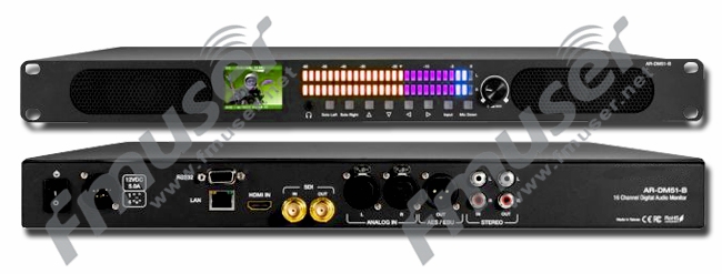
ਕਿਵੇਂ ਕਰਦਾ ਹੈ ਰੈਕ ਆਡੀਓ ਮਾਨੀਟਰ ਕੰਮ ਕਰਨ?
ਆਡੀਓ ਮਾਨੀਟਰ ਇੱਕ ਕਿਸਮ ਦਾ ਕਿਰਿਆਸ਼ੀਲ ਉਪਕਰਣ ਹੈ, ਸਪੀਕਰਾਂ ਨਾਲ ਲੈਸ, ਆਉਟਪੁੱਟ ਪਾਵਰ ਨੂੰ ਵੱਧ ਤੋਂ ਵੱਧ ਕਰ ਸਕਦਾ ਹੈ, ਫਰੰਟ ਡਿਜੀਟਲ ਪੈਨਲ, ਹੋਰ ਆਸਾਨੀ ਨਾਲ ਚਲਾਇਆ ਜਾ ਸਕਦਾ ਹੈ। ਇਸਦੀ ਵਰਤੋਂ ਇਹ ਨਿਰੀਖਣ ਕਰਨ ਲਈ ਵੀ ਕੀਤੀ ਜਾਂਦੀ ਹੈ ਕਿ ਕੀ ਇਨਪੁਟ ਆਡੀਓ ਪ੍ਰੋਗਰਾਮ ਸਹੀ ਹੈ ਜਾਂ ਨਹੀਂ ਅਤੇ ਅੰਤ ਵਿੱਚ ਐਫਐਮ ਪ੍ਰਸਾਰਣ ਟ੍ਰਾਂਸਮੀਟਰ ਵਿੱਚ ਇਨਪੁਟ ਕੀਤੇ ਜਾਣ ਤੋਂ ਪਹਿਲਾਂ ਆਡੀਓ ਗੁਣਵੱਤਾ ਦੀ ਨਿਗਰਾਨੀ ਕਰਨ ਲਈ।
ਇਸੇ ਰੈਕ ਆਡੀਓ ਮਾਨੀਟਰ ਮਹੱਤਵਪੂਰਨ ਹੈ?
ਆਡੀਓ ਮਾਨੀਟਰ ਦੀ ਵਰਤੋਂ ਅਕਸਰ ਕਿਸੇ ਵੀ ਸਟੀਰੀਓ ਲਾਈਨ-ਪੱਧਰ ਦੇ ਆਉਟਪੁੱਟ ਤੋਂ ਆਵਾਜ਼ ਦੀ ਨਿਗਰਾਨੀ ਕਰਨ ਲਈ ਕੀਤੀ ਜਾਂਦੀ ਹੈ, ਬਾਹਰੀ ਬੈਕਗ੍ਰਾਉਂਡ ਸੰਗੀਤ ਦੇ ਨਿਯੰਤਰਣ ਅਤੇ ਪੇਜਿੰਗ ਪ੍ਰਣਾਲੀ ਦੇ ਸਖਤ ਨਿਯੰਤਰਣ ਨੂੰ ਯਕੀਨੀ ਬਣਾਉਣ ਲਈ। ਸੰਯੁਕਤ ਰਾਜ ਵਿੱਚ ਆਮ ਆਡੀਓ ਮਾਨੀਟਰ ਵਿਗਾੜ, ਸ਼ੋਰ, ਜਾਂ ਜ਼ਮੀਨੀ ਲੂਪਸ (ਬਿਨਾਂ ਟ੍ਰਾਂਸਫਾਰਮਰ) ਦੇ ਸਿਗਨਲ ਦੀ ਇਕਸਾਰਤਾ ਨੂੰ ਬਣਾਈ ਰੱਖਣ ਲਈ ਹਰੇਕ ਇਨਪੁਟ 'ਤੇ DC ਕਪਲਿੰਗ ਕੈਪੇਸੀਟਰਾਂ ਨਾਲ ਲੈਸ ਹੁੰਦੇ ਹਨ। ਰੈਕ ਡਿਜ਼ਾਈਨ ਰੈਕ-ਮਾਊਂਟ ਕੀਤੇ ਆਡੀਓ ਮਾਨੀਟਰਾਂ ਨੂੰ ਬਹੁਤ ਹੀ ਸੰਖੇਪ ਐਪਲੀਕੇਸ਼ਨਾਂ ਵਿੱਚ ਸਥਾਪਤ ਕਰਨ ਦੇ ਯੋਗ ਬਣਾਉਂਦਾ ਹੈ, ਜੋ ਅੰਦਰੂਨੀ ਥਾਂਵਾਂ ਦੀ ਵਰਤੋਂ ਨੂੰ ਘਟਾਉਂਦਾ ਹੈ।
ਇਹ ਇਕਾਈਆਂ VTR ਬਰੈਕਟਾਂ, ਮੋਬਾਈਲ ਉਤਪਾਦਨ ਵਾਹਨਾਂ, ਟੈਲੀਕਾਨਫਰੰਸ ਯੰਤਰਾਂ, ਮਲਟੀਮੀਡੀਆ ਪ੍ਰਣਾਲੀਆਂ, ਸੈਟੇਲਾਈਟ ਲਿੰਕਾਂ, ਕੇਬਲ ਟੀਵੀ ਸਹੂਲਤਾਂ, ਅਤੇ ਰੇਡੀਓ ਸਟੇਸ਼ਨਾਂ ਵਿੱਚ ਵਰਤਣ ਲਈ ਆਦਰਸ਼ ਹਨ।
ਇਹ ਇਕਾਈਆਂ ਸਪੇਸ-ਨਾਜ਼ੁਕ ਵਾਤਾਵਰਣਾਂ ਵਿੱਚ ਵਰਤਣ ਲਈ ਆਦਰਸ਼ ਹਨ, ਜਿਵੇਂ ਕਿ ਟੀਵੀ ਸਹੂਲਤਾਂ, ਸਟੂਡੀਓ, ਵੀਟੀਆਰ ਬਰੈਕਟ, ਮੋਬਾਈਲ ਉਤਪਾਦਨ ਵਾਹਨ, ਸੈਟੇਲਾਈਟ ਲਿੰਕ, ਅਤੇ ਅਸਲ ਵਿੱਚ ਕੋਈ ਵੀ ਰੈਕ-ਮਾਊਂਟਡ ਵਾਤਾਵਰਣ ਜਿਸ ਲਈ ਮਲਟੀ-ਚੈਨਲ ਆਡੀਓ ਨਿਗਰਾਨੀ ਦੀ ਲੋੜ ਹੁੰਦੀ ਹੈ।
7. ਰੈਕ ਡਿਜੀਟਲ ਐਫਐਮ ਟਿਊਨਰ
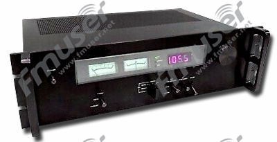
ਕਿਵੇਂ ਕਰਦਾ ਹੈ ਡਿਜੀਟਲ ਐਫਐਮ ਟਿਊਨਰ ਕੰਮ ਕਰਨ?
ਟਿਊਨਰ ਦੀ ਵਰਤੋਂ RF ਸਿਗਨਲਾਂ ਨੂੰ ਪ੍ਰਾਪਤ ਕਰਨ ਅਤੇ ਉਹਨਾਂ ਨੂੰ ਘੱਟ ਮੋਡਿਊਲੇਟਿਡ ਇੰਟਰਮੀਡੀਏਟ ਫ੍ਰੀਕੁਐਂਸੀ (IF) ਵਿੱਚ ਬਦਲਣ ਜਾਂ ਅਨਮੋਡਿਊਲੇਟਡ ਬੇਸਬੈਂਡ ਵਿੱਚ ਹੋਰ ਹੇਠਾਂ-ਕਨਵਰਟ ਕਰਨ ਲਈ ਕੀਤੀ ਜਾਂਦੀ ਹੈ।![]() ਇਹ ਇੱਕ ਅਜਿਹਾ ਯੰਤਰ ਹੈ ਜੋ ਰੇਡੀਓ ਫ੍ਰੀਕੁਐਂਸੀ (RF) ਪ੍ਰਸਾਰਣ ਪ੍ਰਾਪਤ ਕਰਦਾ ਹੈ ਜਿਵੇਂ ਕਿ ਰੇਡੀਓ ਪ੍ਰਸਾਰਣ ਅਤੇ ਚੁਣੀ ਗਈ ਕੈਰੀਅਰ ਬਾਰੰਬਾਰਤਾ ਅਤੇ ਇਸ ਨਾਲ ਸਬੰਧਿਤ ਬੈਂਡਵਿਡਥ ਨੂੰ ਅੱਗੇ ਦੀ ਪ੍ਰਕਿਰਿਆ ਲਈ ਢੁਕਵੀਂ ਇੱਕ ਸਥਿਰ ਬਾਰੰਬਾਰਤਾ ਵਿੱਚ ਬਦਲਦਾ ਹੈ। ਟ੍ਰਾਂਸਮੀਟਿੰਗ ਸਟੇਸ਼ਨ ਅਤੇ ਰੇਡੀਓ ਰਿਸੀਵਰ ਛੋਟੇ ਸਿਗਨਲ ਪ੍ਰਾਪਤ ਕਰਦੇ ਹਨ। ਇਸ ਨੂੰ ਫਿਰ ਟਿਊਨਰ ਰਾਹੀਂ if ਵਿੱਚ ਬਦਲਿਆ ਜਾਂਦਾ ਹੈ। ਇਸ ਨੂੰ ਸਿੱਧੇ ਸੰਸਲੇਸ਼ਣ ਦੁਆਰਾ ਵੀ ਬਦਲਿਆ ਜਾ ਸਕਦਾ ਹੈ। ਫਿਰ ਆਰਐਫ ਸਿਗਨਲ ਨੂੰ ਡਿਟੈਕਟਰ ਵਿੱਚ ਲਿਆਂਦਾ ਜਾਂਦਾ ਹੈ, ਜੋ ਕਿ ਆਰਐਫ ਸਿਗਨਲ ਪ੍ਰਾਪਤ ਕਰਦਾ ਹੈ ਅਤੇ ਇਸਨੂੰ ਆਡੀਓ ਬਾਰੰਬਾਰਤਾ ਵਿੱਚ ਲਿਆਉਂਦਾ ਹੈ। ਆਡੀਓ ਐਂਪਲੀਫਾਇਰ ਫਿਰ ਹੈੱਡਫੋਨ ਜਾਂ ਸਪੀਕਰਾਂ ਰਾਹੀਂ ਪਲੇਬੈਕ ਲਈ ਸਿਗਨਲ ਨੂੰ ਵਧਾਉਂਦਾ ਹੈ। ਟਿਊਨਰ ਇਸ ਰਾਹੀਂ ਵਹਿ ਰਹੇ ਕਰੰਟ ਦੀ ਮਾਤਰਾ (ਜਾਂ ਇਸ ਤਰ੍ਹਾਂ ਦੀ ਕੋਈ ਚੀਜ਼) ਨੂੰ ਬਦਲ ਕੇ ਗੂੰਜਦੀ ਬਾਰੰਬਾਰਤਾ ਦੀ ਚੋਣ ਕਰਦਾ ਹੈ। ਇਸਦਾ ਕੰਮ ਇੱਕ ਸਾਈਨ ਵੇਵ fmuser.-net ਨੂੰ ਐਂਟੀਨਾ ਦੁਆਰਾ ਪ੍ਰਾਪਤ ਹਜ਼ਾਰਾਂ ਰੇਡੀਓ ਸਿਗਨਲਾਂ ਤੋਂ ਵੱਖ ਕਰਨਾ ਹੈ। ਇਸ ਸਥਿਤੀ ਵਿੱਚ, ਟਿਊਨਰ ਨੂੰ 680000 Hz ਸਿਗਨਲ ਪ੍ਰਾਪਤ ਕਰਨ ਲਈ ਟਿਊਨ ਕੀਤਾ ਜਾਵੇਗਾ। ਟਿਊਨਰ ਦਾ ਕੰਮ ਕਰਨ ਦਾ ਸਿਧਾਂਤ ਗੂੰਜਦਾ ਹੈ। ਦੂਜੇ ਸ਼ਬਦਾਂ ਵਿੱਚ, ਰੇ ਕਹਿੰਦਾ ਹੈ, ਟਿਊਨਰ ਹਵਾ ਵਿੱਚ ਹੋਰ ਸਾਰੀਆਂ ਬਾਰੰਬਾਰਤਾਵਾਂ ਨੂੰ ਨਜ਼ਰਅੰਦਾਜ਼ ਕਰਦੇ ਹੋਏ, ਇੱਕ ਖਾਸ ਬਾਰੰਬਾਰਤਾ 'ਤੇ ਗੂੰਜਦਾ ਹੈ ਅਤੇ ਵਧਾਉਂਦਾ ਹੈ।
ਇਹ ਇੱਕ ਅਜਿਹਾ ਯੰਤਰ ਹੈ ਜੋ ਰੇਡੀਓ ਫ੍ਰੀਕੁਐਂਸੀ (RF) ਪ੍ਰਸਾਰਣ ਪ੍ਰਾਪਤ ਕਰਦਾ ਹੈ ਜਿਵੇਂ ਕਿ ਰੇਡੀਓ ਪ੍ਰਸਾਰਣ ਅਤੇ ਚੁਣੀ ਗਈ ਕੈਰੀਅਰ ਬਾਰੰਬਾਰਤਾ ਅਤੇ ਇਸ ਨਾਲ ਸਬੰਧਿਤ ਬੈਂਡਵਿਡਥ ਨੂੰ ਅੱਗੇ ਦੀ ਪ੍ਰਕਿਰਿਆ ਲਈ ਢੁਕਵੀਂ ਇੱਕ ਸਥਿਰ ਬਾਰੰਬਾਰਤਾ ਵਿੱਚ ਬਦਲਦਾ ਹੈ। ਟ੍ਰਾਂਸਮੀਟਿੰਗ ਸਟੇਸ਼ਨ ਅਤੇ ਰੇਡੀਓ ਰਿਸੀਵਰ ਛੋਟੇ ਸਿਗਨਲ ਪ੍ਰਾਪਤ ਕਰਦੇ ਹਨ। ਇਸ ਨੂੰ ਫਿਰ ਟਿਊਨਰ ਰਾਹੀਂ if ਵਿੱਚ ਬਦਲਿਆ ਜਾਂਦਾ ਹੈ। ਇਸ ਨੂੰ ਸਿੱਧੇ ਸੰਸਲੇਸ਼ਣ ਦੁਆਰਾ ਵੀ ਬਦਲਿਆ ਜਾ ਸਕਦਾ ਹੈ। ਫਿਰ ਆਰਐਫ ਸਿਗਨਲ ਨੂੰ ਡਿਟੈਕਟਰ ਵਿੱਚ ਲਿਆਂਦਾ ਜਾਂਦਾ ਹੈ, ਜੋ ਕਿ ਆਰਐਫ ਸਿਗਨਲ ਪ੍ਰਾਪਤ ਕਰਦਾ ਹੈ ਅਤੇ ਇਸਨੂੰ ਆਡੀਓ ਬਾਰੰਬਾਰਤਾ ਵਿੱਚ ਲਿਆਉਂਦਾ ਹੈ। ਆਡੀਓ ਐਂਪਲੀਫਾਇਰ ਫਿਰ ਹੈੱਡਫੋਨ ਜਾਂ ਸਪੀਕਰਾਂ ਰਾਹੀਂ ਪਲੇਬੈਕ ਲਈ ਸਿਗਨਲ ਨੂੰ ਵਧਾਉਂਦਾ ਹੈ। ਟਿਊਨਰ ਇਸ ਰਾਹੀਂ ਵਹਿ ਰਹੇ ਕਰੰਟ ਦੀ ਮਾਤਰਾ (ਜਾਂ ਇਸ ਤਰ੍ਹਾਂ ਦੀ ਕੋਈ ਚੀਜ਼) ਨੂੰ ਬਦਲ ਕੇ ਗੂੰਜਦੀ ਬਾਰੰਬਾਰਤਾ ਦੀ ਚੋਣ ਕਰਦਾ ਹੈ। ਇਸਦਾ ਕੰਮ ਇੱਕ ਸਾਈਨ ਵੇਵ fmuser.-net ਨੂੰ ਐਂਟੀਨਾ ਦੁਆਰਾ ਪ੍ਰਾਪਤ ਹਜ਼ਾਰਾਂ ਰੇਡੀਓ ਸਿਗਨਲਾਂ ਤੋਂ ਵੱਖ ਕਰਨਾ ਹੈ। ਇਸ ਸਥਿਤੀ ਵਿੱਚ, ਟਿਊਨਰ ਨੂੰ 680000 Hz ਸਿਗਨਲ ਪ੍ਰਾਪਤ ਕਰਨ ਲਈ ਟਿਊਨ ਕੀਤਾ ਜਾਵੇਗਾ। ਟਿਊਨਰ ਦਾ ਕੰਮ ਕਰਨ ਦਾ ਸਿਧਾਂਤ ਗੂੰਜਦਾ ਹੈ। ਦੂਜੇ ਸ਼ਬਦਾਂ ਵਿੱਚ, ਰੇ ਕਹਿੰਦਾ ਹੈ, ਟਿਊਨਰ ਹਵਾ ਵਿੱਚ ਹੋਰ ਸਾਰੀਆਂ ਬਾਰੰਬਾਰਤਾਵਾਂ ਨੂੰ ਨਜ਼ਰਅੰਦਾਜ਼ ਕਰਦੇ ਹੋਏ, ਇੱਕ ਖਾਸ ਬਾਰੰਬਾਰਤਾ 'ਤੇ ਗੂੰਜਦਾ ਹੈ ਅਤੇ ਵਧਾਉਂਦਾ ਹੈ।![]()
ਟਿਊਨਰ ਮੂਲ ਰੂਪ ਵਿੱਚ ਇੱਕ ਹਵਾਲਾ ਤਰੰਗ ਲੈਂਦੇ ਹਨ ਅਤੇ ਉਸ ਵੇਵ ਦੀ ਤੁਲਨਾ ਕਰਦੇ ਹਨ ਜੋ ਐਂਟੀਨਾ ਚੁੱਕਦਾ ਹੈ, ਅਤੇ ਟਿਊਨਰ ਦੀਆਂ ਕਈ ਕਿਸਮਾਂ ਹਨ:
- AM
- FM
- ਐਨਾਲਾਗ ਟੀਵੀ - NTSC
- ਐਨਾਲਾਗ ਟੀਵੀ - PAL
- ਡਿਜੀਟਲ
ਇਸੇ ਡਿਜੀਟਲ ਐਫਐਮ ਟਿਊਨਰ ਮਹੱਤਵਪੂਰਨ ਹੈ?
FM ਟਿਊਨਰ ਦੂਜੇ ਸਟੇਸ਼ਨਾਂ ਤੋਂ FM ਸਿਗਨਲ ਪ੍ਰਾਪਤ ਕਰ ਸਕਦਾ ਹੈ ਅਤੇ ਉਹਨਾਂ ਨੂੰ ਟ੍ਰਾਂਸਮੀਟਰ ਵਿੱਚ ਇਨਪੁਟ ਕਰ ਸਕਦਾ ਹੈ। ਇਹ ਦੂਜੇ ਰੇਡੀਓ ਤੋਂ ਪ੍ਰੋਗਰਾਮ ਪ੍ਰਸਾਰਿਤ ਕਰ ਸਕਦਾ ਹੈ। ਪ੍ਰਸਾਰਣ ਦੇ ਸ਼ੁਰੂਆਤੀ ਦਿਨਾਂ ਵਿੱਚ, ਐਂਟੀਨਾ ਦੀ ਗੂੰਜ ਅਤੇ ਇਸ ਨਾਲ ਸੰਬੰਧਿਤ ਇੰਡਕਟੈਂਸ ਅਤੇ ਕੈਪੈਸੀਟੈਂਸ ਵਿਸ਼ੇਸ਼ਤਾਵਾਂ ਅਸਲ ਵਿੱਚ ਉਹ ਆਈਟਮਾਂ ਸਨ ਜਿਸਨੂੰ ਤੁਸੀਂ ਸੁਣਨਾ ਚਾਹੁੰਦੇ ਹੋ "ਡਾਇਲ" ਕਰੋ। ਤੁਸੀਂ ਅਸਲ ਵਿੱਚ ਐਂਟੀਨਾ ਦੀ ਲੰਬਾਈ ਨੂੰ ਨਹੀਂ ਬਦਲਦੇ, ਪਰ ਤੁਸੀਂ ਐਂਟੀਨਾ ਨਾਲ ਜੁੜੇ ਇੰਡਕਟਰ (ਕੋਇਲ) ਜਾਂ ਕੈਪਸੀਟਰ ਨੂੰ ਬਦਲ ਕੇ ਗੂੰਜ ਨੂੰ ਟਿਊਨ ਕਰ ਸਕਦੇ ਹੋ। ਆਉਟਪੁੱਟ ਸਿਗਨਲ ਇੱਕ AC ਵੋਲਟੇਜ ਹੈ, ਅਤੇ ਇਸਨੂੰ ਇੱਕ ਡਾਇਓਡ (ਫਿਰ "ਕ੍ਰਿਸਟਲ" ਕਿਹਾ ਜਾਂਦਾ ਹੈ) ਨਾਲ ਸੁਧਾਰ ਕੇ, ਤੁਸੀਂ ਕੈਰੀਅਰ ਐਪਲੀਟਿਊਡ ਤਬਦੀਲੀ ਦੇ ਰੂਪ ਵਿੱਚ ਮੋਡੀਊਲੇਟ ਕੀਤੇ ਸਿਗਨਲ ਨੂੰ ਐਕਸਟਰੈਕਟ ਕਰ ਸਕਦੇ ਹੋ। ਜਿਵੇਂ ਕਿ FMUSER-Ray ਸਮਝਦਾ ਹੈ, ਇਹ ਸਭ ਬਿਨਾਂ ਕਿਸੇ ਬੈਟਰੀ ਦੇ ਹੈ!
FM-ਪਰ ਅਸਲ ਵਿੱਚ, ਇੱਕ ਆਮ ਆਧੁਨਿਕ ਰੇਡੀਓ ਵਿੱਚ ਐਂਟੀਨਾ ਇੱਕ ਅਜਿਹਾ ਭਾਗ ਨਹੀਂ ਹੈ ਜੋ ਚੁਣੀ ਹੋਈ ਪ੍ਰਸਾਰਣ ਬਾਰੰਬਾਰਤਾ ਵਿੱਚ "ਪਲੱਗ" ਕਰਦਾ ਹੈ। ਇਹ ਸੱਚ ਹੈ ਕਿ ਐਂਟੀਨਾ ਸਰਕਟ ਨੂੰ ਉਸ ਬੈਂਡ ਵਿੱਚ ਗੂੰਜਣਾ ਚਾਹੀਦਾ ਹੈ ਜਿਸ ਵਿੱਚ ਤੁਸੀਂ ਦਿਲਚਸਪੀ ਰੱਖਦੇ ਹੋ, fmuser.-net ਪਰ ਫਿਰ ਬ੍ਰੌਡਬੈਂਡ ਸਿਗਨਲ ਨੂੰ ਐਨਾਲਾਗ ਕੰਪੋਨੈਂਟ ਵਿੱਚ ਰੇਡੀਓ ਵਿੱਚ ਅੰਦਰੂਨੀ ਤੌਰ 'ਤੇ ਤਿਆਰ ਕੀਤੇ ਗਏ ਸਾਈਨਸੌਇਡਲ ਸਿਗਨਲ ਨਾਲ ਮਿਲਾਇਆ ਜਾਂਦਾ ਹੈ, ਜੋ ਬਾਰੰਬਾਰਤਾ ਨੂੰ ਘਟਾਉਂਦਾ ਹੈ ਅਤੇ ਬਾਕੀ ਨੂੰ ਬਣਾਉਂਦਾ ਹੈ। ਸੰਭਵ ਹੈ। ਰੇਡੀਓ ਇੱਕ ਬਹੁਤ ਹੀ ਆਸਾਨੀ ਨਾਲ ਹੈਂਡਲ ਕਰਨ ਵਾਲੇ ਫ੍ਰੀਕੁਐਂਸੀ ਬੈਂਡ (ਜੇ ਕਹਿੰਦੇ ਹਨ) ਵਿੱਚ ਕੰਮ ਕਰਦਾ ਹੈ। ਮਿਕਸਰ ਵਿੱਚ, ਤੁਸੀਂ ਆਧੁਨਿਕ ਸੁਪਰਹੀਟਰੋਡਾਈਨ ਰੇਡੀਓ ਰਿਸੀਵਰ ਵਿੱਚ ਰਿਸੈਪਸ਼ਨ ਪ੍ਰਭਾਵ ਨੂੰ ਅਨੁਕੂਲ ਕਰ ਸਕਦੇ ਹੋ। ਐਂਟੀਨਾ ਸਰਕਟ ਦੀ ਗੂੰਜ ਨੂੰ ਬਦਲਣ ਨਾਲੋਂ ਸਟੀਕ ਟਿਊਨਿੰਗ ਬਾਰੰਬਾਰਤਾ ਨੂੰ ਸਿੰਥੇਸਾਈਜ਼ ਕਰਨਾ ਬਹੁਤ ਸੌਖਾ ਹੈ।
ਉਪਭੋਗਤਾ-ਬਾਕੀ ਅਸਲ ਭੌਤਿਕ ਵਿਗਿਆਨ ਨਹੀਂ ਹੈ, ਪਰ ਐਨਾਲਾਗ ਰੇਡੀਓ ਅਤੇ ਡਿਜੀਟਲ ਰੇਡੀਓ ਵਿਚਕਾਰ ਅੰਤਰ ਸਰਕਟ ਵਿੱਚ ਹੈ। ਅਸਲ ਵਿੱਚ, ਐਨਾਲਾਗ ਰੇਡੀਓ ਇੰਟਰਮੀਡੀਏਟ ਫ੍ਰੀਕੁਐਂਸੀ ਤੋਂ ਮੋਡਿਊਲੇਟਡ ਸਿਗਨਲ ਕੱਢਦਾ ਹੈ, ਜਿਸਨੂੰ ਵਧਾਇਆ ਜਾਂਦਾ ਹੈ ਅਤੇ ਲਾਊਡਸਪੀਕਰ ਜਾਂ ਰੇਡੀਓ ਆਉਟਪੁੱਟ ਨੂੰ ਭੇਜਿਆ ਜਾਂਦਾ ਹੈ। ਡਿਜੀਟਲ ਪ੍ਰਸਾਰਣ ਵਿੱਚ, ਸਿਗਨਲ ਆਡੀਓ ਦੇ ਡਿਜੀਟਲ ਸੰਸਕਰਣ ਨੂੰ ਦਰਸਾਉਂਦਾ ਹੈ, ਜਿਵੇਂ ਕਿ ਕੰਪਿਊਟਰ 'ਤੇ ਵੇਵ ਜਾਂ MP3 ਫਾਈਲ ਇੱਕ ਡਿਜੀਟਲ ਪ੍ਰਤੀਨਿਧਤਾ ਹੈ, ਇਸ ਨੂੰ ਐਨਾਲਾਗ ਸਿਗਨਲ ਵਿੱਚ ਵਾਪਸ ਬਦਲਿਆ ਜਾ ਸਕਦਾ ਹੈ ਜੋ ਸਪੀਕਰ ਨੂੰ ਭੇਜਿਆ ਜਾ ਸਕਦਾ ਹੈ। ਇਸਦਾ ਫਾਇਦਾ ਇਹ ਹੈ ਕਿ ਹਵਾ ਵਿੱਚ ਡਿਜੀਟਲ ਸਿਗਨਲਾਂ ਦੀ ਬੈਂਡਵਿਡਥ ਦੀ ਲੋੜ (ਸੰਭਾਵੀ ਤੌਰ 'ਤੇ) ਘਟਾਈ ਜਾ ਸਕਦੀ ਹੈ, fmuser.-net ਤਾਂ ਜੋ ਤੁਸੀਂ ਉਸੇ "ਏਅਰਸਪੇਸ" ਵਿੱਚ ਹੋਰ ਸਿਗਨਲਾਂ ਨੂੰ ਅਨੁਕੂਲਿਤ ਕਰ ਸਕੋ, ਅਤੇ ਡਿਜੀਟਲ ਸਿਗਨਲ ਸ਼ੋਰ ਲਈ ਸੰਵੇਦਨਸ਼ੀਲ ਨਹੀਂ ਹੁੰਦੇ ਹਨ। ਜਿਵੇਂ ਕਿ ਰੇ "ਹਾਂ" ਲਿਖਦਾ ਹੈ ਕਿਉਂਕਿ ਬਦਕਿਸਮਤੀ ਨਾਲ, ਬਹੁਤ ਸਾਰੇ ਵਪਾਰਕ ਡਿਜੀਟਲ ਰੇਡੀਓ / ਟੀਵੀ ਸਟੇਸ਼ਨ ਅਜਿਹਾ ਨਹੀਂ ਕਰਦੇ, ਰੇ ਕਹਿੰਦਾ ਹੈ।
FMUSER। ਮੈਂ ਇਹ ਦੁਹਰਾਉਂਦਾ ਹਾਂ ਕਿ "ਡਿਜੀਟਲ" ਰੇਡੀਓ ਵਿੱਚ, ਪ੍ਰਾਪਤ ਕਰਨ ਵਾਲੀ ਬਾਰੰਬਾਰਤਾ ਨੂੰ ਚੁਣਨ ਵਾਲੇ ਹਿੱਸੇ ਅਜੇ ਵੀ ਐਨਾਲਾਗ ਹਨ, ਪਰ ਮਿਕਸਡ (ਟਿਊਨਡ) ਬਾਰੰਬਾਰਤਾ ਡਿਜੀਟਲ ਤੌਰ 'ਤੇ ਨਿਯੰਤਰਿਤ ਅਤੇ ਚੁਣੀ ਗਈ ਹੈ।![]()
ਇੱਕ ਹੋਰ ਦਿਲਚਸਪ ਗੱਲ ਇਹ ਹੈ ਕਿ ਸਾਫਟਵੇਅਰ-ਪਰਿਭਾਸ਼ਿਤ ਰੇਡੀਓ (SDR), ਜੋ ਕਿ ਜੇ (ਜਾਂ ਕੁਝ ਮਾਮਲਿਆਂ ਵਿੱਚ ਸਿੱਧੇ ਐਂਟੀਨਾ ਫ੍ਰੀਕੁਐਂਸੀ) ਨੂੰ ਇੱਕ ਡਿਜੀਟਲ ਸਿਗਨਲ ਵਿੱਚ ਬਦਲਣ ਦਾ ਸਿਧਾਂਤ ਹੈ ਅਤੇ ਇੱਕ ਪੂਰੇ ਸਾਫਟਵੇਅਰ ਅੱਪਗਰੇਡ ਹੋਣ ਯੋਗ ਸਿਗਨਲ ਪ੍ਰੋਸੈਸਰ fmuser.-net ਦੁਆਰਾ ਇਸਨੂੰ ਡੀਮੋਡਿਊਲ ਕਰਨਾ ਹੈ। ਕਿਉਂਕਿ ਇਲੈਕਟ੍ਰਾਨਿਕ ਕੰਪੋਨੈਂਟਾਂ ਨੂੰ ਵੇਲਡ ਕਰਨ ਨਾਲੋਂ ਨਵੇਂ ਸੌਫਟਵੇਅਰ ਨੂੰ ਪ੍ਰੋਗ੍ਰਾਮ ਕਰਨਾ ਬਹੁਤ ਸੌਖਾ ਹੈ, ਇਸ ਨਾਲ ਰੇਡੀਓ ਉਤਸਾਹੀਆਂ ਵਿੱਚ ਵਿਆਪਕ ਦਿਲਚਸਪੀ ਪੈਦਾ ਹੋਈ ਹੈ।![]()
ਜੇਕਰ ਤੁਸੀਂ SDR ਨੂੰ ਸ਼ਾਮਲ ਕਰਦੇ ਹੋ ਅਤੇ ਇਸਨੂੰ ਬਿਨਾਂ ਕਿਸੇ ਵਿਚਕਾਰਲੀ ਬਾਰੰਬਾਰਤਾ (ਐਂਟੈਨਾ ਨੂੰ ਐਨਾਲਾਗ-ਟੂ-ਡਿਜੀਟਲ ਕਨਵਰਟਰ ਅਤੇ ਸਿਗਨਲ ਪ੍ਰੋਸੈਸਰ ਨਾਲ ਜੋੜਦੇ ਹੋਏ) ਦੀ ਵਰਤੋਂ ਕੀਤੇ ਬਿਨਾਂ ਲਾਗੂ ਕਰਦੇ ਹੋ, ਤਾਂ ਤੁਹਾਡੀਆਂ ਜ਼ਰੂਰਤਾਂ ਦੇ ਅਨੁਸਾਰ ਸਿਗਨਲ ਸਰੋਤ ਨੂੰ ਅਨੁਕੂਲ ਕਰਨ ਦਾ ਇੱਕ ਸ਼ੁੱਧ ਸਾਫਟਵੇਅਰ ਤਰੀਕਾ ਹੈ, ਹਾਲਾਂਕਿ ਇਹ ਨਹੀਂ ਹੈ। ਵਰਤਮਾਨ ਵਿੱਚ ਡਿਜੀਟਲ ਰੇਡੀਓ ਲਈ ਕੰਮ ਕਰਨ ਦਾ ਸਭ ਤੋਂ ਆਮ ਤਰੀਕਾ।
8. ਆਡੀਓ ਫਾਲਟ ਅਲਾਰਮ
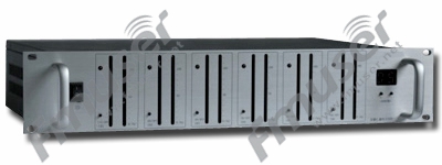
ਕਿਵੇਂ ਕਰਦਾ ਹੈ ਆਡੀਓ ਫਾਲਟ ਅਲਾਰਮ ਕੰਮ ਕਰਨ?
ਆਡੀਓ ਇੰਪੁੱਟ ਦੀ ਨਿਗਰਾਨੀ ਕਰਕੇ, ਆਡੀਓ ਫਾਲਟ ਅਲਾਰਮ ਕਰ ਸਕਦਾ ਹੈ ਆਡੀਓ ਇਨਪੁਟ ਦੀ ਗੁਣਵੱਤਾ ਨੂੰ ਯਕੀਨੀ ਬਣਾਉਣ ਲਈ ਸਮਕਾਲੀ ਤੌਰ 'ਤੇ ਕਈ ਆਡੀਓ ਚੈਨਲਾਂ ਦੀ ਨਿਗਰਾਨੀ ਕਰੋ
ਇਸੇ ਆਡੀਓ ਫਾਲਟ ਅਲਾਰਮ ਮਹੱਤਵਪੂਰਨ ਹੈ?
ਆਡੀਓ ਚੈਨਲ ਦੀ ਨਿਗਰਾਨੀ ਕਰਨ ਤੋਂ ਇਲਾਵਾ, ਸਭ ਤੋਂ ਮਹੱਤਵਪੂਰਨ ਗੱਲ ਇਹ ਹੈ ਕਿ ਆਡੀਓ ਫਾਲਟ ਅਲਾਰਮ ਆਡੀਓ ਨੁਕਸ ਦਾ ਪਤਾ ਲਗਾ ਸਕਦਾ ਹੈ ਅਤੇ ਸਮੇਂ ਸਿਰ ਅਲਾਰਮ ਭੇਜ ਸਕਦਾ ਹੈ.
9. UPS ਪਾਵਰ ਸਪਲਾਈ
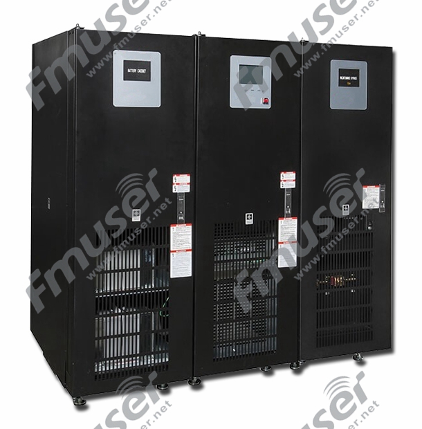
ਕਿਵੇਂ ਕਰਦਾ ਹੈ UPS ਪਾਵਰ ਸਪਲਾਈ ਕੰਮ ਕਰਨ?
ਇੱਕ ਨਿਰਵਿਘਨ ਪਾਵਰ ਸਪਲਾਈ (UPS), ਜਿਸਨੂੰ ਸਟੈਂਡਬਾਏ ਬੈਟਰੀ ਵੀ ਕਿਹਾ ਜਾਂਦਾ ਹੈ, ਇੰਪੁੱਟ ਪਾਵਰ ਸਪਲਾਈ ਦੇ ਉਤਰਾਅ-ਚੜ੍ਹਾਅ ਪ੍ਰਤੀ ਬਹੁਤ ਸੰਵੇਦਨਸ਼ੀਲ ਹੁੰਦਾ ਹੈ ਜੋ ਬੈਕਅੱਪ ਪਾਵਰ ਪ੍ਰਦਾਨ ਕਰਦਾ ਹੈ ਜਦੋਂ ਤੁਹਾਡਾ ਨਿਯਮਤ ਪਾਵਰ ਸਰੋਤ fmuser.-net ਜਾਂ ਵੋਲਟੇਜ ਅਸਵੀਕਾਰਨਯੋਗ ਪੱਧਰ ਤੱਕ ਡਿੱਗ ਜਾਂਦਾ ਹੈ। ਇਹ ਇੱਕ ਕਿਸਮ ਦਾ ਸਟੈਂਡਬਾਏ ਨਿਰੰਤਰ ਪਾਵਰ ਸਪਲਾਈ ਸਿਸਟਮ ਹੈ ਜੋ ਉਪਕਰਨਾਂ ਨੂੰ ਬਿਜਲੀ ਸਪਲਾਈ ਕਰਦਾ ਹੈ ਜਦੋਂ ਉਪਕਰਨ ਦੀ ਮੁੱਖ ਪਾਵਰ ਸਪਲਾਈ ਡਿਸਕਨੈਕਟ ਕੀਤੀ ਜਾਂਦੀ ਹੈ। UPS ਵਿੱਚ ਇੱਕ ਬੈਟਰੀ ਹੁੰਦੀ ਹੈ, ਜੋ "ਪਲੱਗਇਨ" ਕਰੇਗੀ ਜਦੋਂ ਡਿਵਾਈਸ ਮੁੱਖ ਪਾਵਰ ਸਪਲਾਈ ਦੀ ਪਾਵਰ ਅਸਫਲਤਾ ਦਾ ਪਤਾ ਲਗਾਉਂਦੀ ਹੈ, ਬੈਟਰੀ ਵਿੱਚ ਸਟੋਰ ਕੀਤੀ ਊਰਜਾ ਪ੍ਰਦਾਨ ਕਰਦੀ ਹੈ, fmuser.-net, supercapacitor, ਜਾਂ flywheel, ਦੇ ਰੁਕਾਵਟ ਲਈ ਨੇੜੇ-ਤਤਕਾਲ ਸੁਰੱਖਿਆ ਪ੍ਰਦਾਨ ਕਰਦੀ ਹੈ। ਇੰਪੁੱਟ ਪਾਵਰ ਸਪਲਾਈ ਤਾਂ ਜੋ ਪਾਵਰ-ਆਫ ਡਿਵਾਈਸ ਘੱਟੋ-ਘੱਟ ਥੋੜ੍ਹੇ ਸਮੇਂ ਲਈ ਚੱਲ ਸਕੇ। UPS ਸਾਜ਼ੋ-ਸਾਮਾਨ ਐਂਟੀ-ਸਰਜ ਸੁਰੱਖਿਆ ਵੀ ਪ੍ਰਦਾਨ ਕਰਦਾ ਹੈ। UPS ਦਾ ਆਕਾਰ ਅਤੇ ਡਿਜ਼ਾਈਨ ਇਹ ਨਿਰਧਾਰਤ ਕਰਦਾ ਹੈ ਕਿ ਇਹ ਕਿੰਨੀ ਦੇਰ ਤੱਕ ਬਿਜਲੀ ਸਪਲਾਈ ਕਰੇਗਾ। ਛੋਟਾ UPS ਸਿਸਟਮ ਕਈ ਮਿੰਟਾਂ ਲਈ ਪਾਵਰ ਪ੍ਰਦਾਨ ਕਰ ਸਕਦਾ ਹੈ, ਜੋ ਕਿ ਕੰਪਿਊਟਰ ਪਾਵਰ ਨੂੰ ਕ੍ਰਮਵਾਰ ਬੰਦ ਕਰਨ ਲਈ ਕਾਫ਼ੀ ਹੈ, ਜਦੋਂ ਕਿ ਵੱਡੇ ਸਿਸਟਮ ਵਿੱਚ ਜਨਰੇਟਰ ਦੁਆਰਾ ਆਪਣੇ ਕਬਜ਼ੇ ਵਿੱਚ ਲੈਣ ਤੱਕ ਕਈ ਘੰਟਿਆਂ ਤੱਕ ਚੱਲਣ ਲਈ ਕਾਫ਼ੀ ਬੈਟਰੀ ਪਾਵਰ ਹੁੰਦੀ ਹੈ।![]()
ਆਮ ਅਪਸ ਨੂੰ ਹੇਠ ਲਿਖੀਆਂ ਤਿੰਨ ਕਿਸਮਾਂ ਵਿੱਚ ਵੰਡਿਆ ਗਿਆ ਹੈ:
- ਸਟੈਂਡਬਾਏ UPS
- ਔਨਲਾਈਨ UPS
- ਔਨਲਾਈਨ ਇੰਟਰਐਕਟਿਵ UPS
ਤੁਹਾਡੇ ਰੇਡੀਓ ਸਟੇਸ਼ਨ ਨੂੰ ਇੱਕ ਨਿਰਵਿਘਨ ਬਿਜਲੀ ਸਪਲਾਈ ਜੋੜਨਾ ਇਹ ਯਕੀਨੀ ਬਣਾਉਣ ਦਾ ਇੱਕ ਵਧੀਆ ਤਰੀਕਾ ਹੈ ਕਿ ਇੱਕ ਮਹੱਤਵਪੂਰਨ ਸਮੇਂ 'ਤੇ ਬਿਜਲੀ ਵਿੱਚ ਰੁਕਾਵਟ ਹੈ
- UPS ਦਾ ਕੰਮ ਵਿਹਾਰਕ ਅਤੇ ਸਧਾਰਨ ਹੈ
- ਮੁਕਾਬਲਤਨ ਛੋਟੇ ਵਾਧੇ ਨੂੰ ਜਜ਼ਬ ਕਰੋ।
- ਸ਼ੋਰ ਬਿਜਲੀ ਸਪਲਾਈ ਨੂੰ ਖਤਮ ਕਰੋ.
- ਲਾਈਨ ਡਰਾਪ ਦੌਰਾਨ ਸਾਜ਼ੋ-ਸਾਮਾਨ ਲਈ ਲਗਾਤਾਰ ਬਿਜਲੀ ਸਪਲਾਈ.
- ਲੰਬੇ ਸਮੇਂ ਤੱਕ ਬਿਜਲੀ ਦੀ ਅਸਫਲਤਾ ਦੀ ਸਥਿਤੀ ਵਿੱਚ ਉਪਕਰਣ ਆਪਣੇ ਆਪ ਬੰਦ ਹੋ ਜਾਣਗੇ।
- ਪਾਵਰ ਸਥਿਤੀ ਦੀ ਨਿਗਰਾਨੀ ਅਤੇ ਰਿਕਾਰਡ ਕਰੋ.
- ਡਿਵਾਈਸ ਦੀ ਵੋਲਟੇਜ / ਵਰਤਮਾਨ ਖਪਤ ਨੂੰ ਦਰਸਾਉਂਦਾ ਹੈ।
- ਇੱਕ ਲੰਬੀ ਪਾਵਰ ਅਸਫਲਤਾ ਦੇ ਬਾਅਦ ਉਪਕਰਣ ਨੂੰ ਮੁੜ ਚਾਲੂ ਕਰੋ.
- ਮੌਜੂਦਾ ਪਾਵਰ ਲਾਈਨ 'ਤੇ ਵੋਲਟੇਜ ਦਿਖਾਉਂਦਾ ਹੈ।
- ਕੁਝ ਗਲਤੀ ਸਥਿਤੀਆਂ ਵਿੱਚ ਚੇਤਾਵਨੀਆਂ ਪ੍ਰਦਾਨ ਕਰੋ।
- ਸ਼ਾਰਟ ਸਰਕਟ ਸੁਰੱਖਿਆ ਪ੍ਰਦਾਨ ਕਰੋ.

ਕਿਉਂ ਨਿਰਵਿਘਨ ਪਾਵਰ ਸਪਲਾਈ ਮਹੱਤਵਪੂਰਨ ਹੈ?
ਇੱਕ ਨਿਰਵਿਘਨ ਪਾਵਰ ਸਪਲਾਈ (UPS) ਖਾਸ ਪਾਵਰ ਸਪਲਾਈ ਸਮੱਸਿਆਵਾਂ ਤੋਂ ਨਾਜ਼ੁਕ ਲੋਡਾਂ ਦੀ ਰੱਖਿਆ ਕਰਨ ਲਈ ਤਿਆਰ ਕੀਤੀ ਗਈ ਹੈ, ਜਿਸ ਵਿੱਚ ਸਪਾਈਕ, ਪਾਵਰ ਫੇਲ੍ਹ ਹੋਣ, ਉਤਰਾਅ-ਚੜ੍ਹਾਅ, ਅਤੇ ਪਾਵਰ ਆਊਟੇਜ ਸ਼ਾਮਲ ਹਨ। UPS ਖਾਸ ਤੌਰ 'ਤੇ ਹਾਰਡਵੇਅਰ ਸੁਰੱਖਿਆ ਲਈ ਪ੍ਰਮੁੱਖ ਹੈ। ਰੈਕ ਰੂਮ ਵਿੱਚ ਯੂਪੀਐਸ ਪਾਵਰ ਸਪਲਾਈ ਬਿਜਲੀ ਦੀ ਸਪਲਾਈ ਨੂੰ ਸਥਿਰ ਕਰ ਸਕਦੀ ਹੈ ਅਤੇ ਉਪਕਰਣ ਦੀ ਅਸਫਲਤਾ ਜਾਂ ਅਸਥਿਰ ਗਰਿੱਡ ਦੇ ਕਾਰਨ ਗੈਰ-ਸੰਚਾਲਨ ਨੂੰ ਰੋਕਣ ਲਈ ਜਾਂ ਬਿਜਲੀ ਦੇ ਕਾਰਨ ਉਪਕਰਣ ਨੂੰ ਕੰਮ ਕਰਨ ਤੋਂ ਰੋਕਣ ਲਈ ਥੋੜ੍ਹੇ ਸਮੇਂ ਵਿੱਚ fmuser-net ਨੂੰ ਬਿਜਲੀ ਸਪਲਾਈ ਕਰ ਸਕਦੀ ਹੈ। ਅਸਫਲਤਾ ਜਾਂ ਟ੍ਰਿਪਿੰਗ fmuser.-net. ਕੁਝ ਐਪਲੀਕੇਸ਼ਨ ਦ੍ਰਿਸ਼ਾਂ ਵਿੱਚ ਜੋ ਪਾਵਰ ਅਸਫਲਤਾਵਾਂ ਦੇ ਨਕਾਰਾਤਮਕ ਪ੍ਰਭਾਵ ਲਈ ਕਮਜ਼ੋਰ ਹੁੰਦੇ ਹਨ, ਜਿਵੇਂ ਕਿ ਦੂਰਸੰਚਾਰ ਉਪਕਰਣ ਜਾਂ ਕੰਪਿਊਟਰ, ਅਚਾਨਕ ਪਾਵਰ ਅਸਫਲਤਾ ਮਸ਼ੀਨ ਨੂੰ ਨੁਕਸਾਨ ਪਹੁੰਚਾ ਸਕਦੀ ਹੈ ਅਤੇ ਕੁਝ ਮਹੱਤਵਪੂਰਨ ਫਾਈਲਾਂ ਦੇ ਨੁਕਸਾਨ, ਜਾਂ ਇੱਥੋਂ ਤੱਕ ਕਿ ਜਾਨੀ ਨੁਕਸਾਨ ਦਾ ਕਾਰਨ ਬਣ ਸਕਦੀ ਹੈ। fmuser.-net ਇੱਕ ਸੁਪਰ ਵੱਡੇ ਪੇਸ਼ੇਵਰ ਰੇਡੀਓ ਸਟੇਸ਼ਨ ਲਈ, UPS ਜ਼ਰੂਰੀ ਹੈ। UPS ਬੈਟਰੀ ਸਿਸਟਮ ਤੁਹਾਨੂੰ ਅਤੇ ਤੁਹਾਡੇ ਰੇਡੀਓ ਸਟੇਸ਼ਨ ਨੂੰ ਬਿਜਲੀ ਦੀ ਅਸਫਲਤਾ ਦੀ ਸਥਿਤੀ ਵਿੱਚ ਨੁਕਸਾਨ ਤੋਂ ਬਚਾ ਸਕਦਾ ਹੈ ਤਾਂ ਜੋ ਤੁਹਾਡੇ ਮਹਿੰਗੇ ਰੇਡੀਓ ਸਟੇਸ਼ਨ ਉਪਕਰਣ ਆਪਣੇ ਆਪ ਹੀ ਕੰਮ ਕਰ ਸਕਣ। fmuser-net ਇੱਕ ਵੀਡੀਓ ਮਾਨੀਟਰ ਤੋਂ ਬਿਨਾਂ ਸਮੇਂ ਦੀ ਇੱਕ ਮਿਆਦ ਲਈ ਉਦੋਂ ਤੱਕ ਚਲਾਓ ਜਦੋਂ ਤੱਕ ਮੁੱਖ ਸ਼ਕਤੀ ਨਹੀਂ ਆ ਜਾਂਦੀ। ਹਸਪਤਾਲਾਂ, ਬੈਂਕਾਂ ਅਤੇ ਹੋਰ ਮਹੱਤਵਪੂਰਨ ਅਦਾਰਿਆਂ ਵਿੱਚ, ਇਹ ਕੀਮਤੀ ਮਿੰਟ ਜ਼ਿੰਦਗੀ ਅਤੇ ਮੌਤ ਦਾ ਮਾਮਲਾ ਹੋ ਸਕਦੇ ਹਨ। UPS ਤੁਰੰਤ ਜਵਾਬ ਦੇ ਸਕਦਾ ਹੈ ਜਦੋਂ ਮੁੱਖ ਪਾਵਰ ਕੱਟਿਆ ਜਾਂਦਾ ਹੈ, ਰੇ ਕਹਿੰਦਾ ਹੈ, ਅਤੇ ਸਿਸਟਮ ਲਈ ਸ਼ਕਤੀਸ਼ਾਲੀ ਪਾਵਰ ਪ੍ਰਦਾਨ ਕਰਦਾ ਹੈ, ਅਤੇ ਫਿਰ ਇਸਨੂੰ ਚਾਲੂ ਕਰਨ ਅਤੇ ਚੱਲਣ ਤੋਂ ਤੁਰੰਤ ਬਾਅਦ ਬੈਕਅੱਪ ਸਿਸਟਮ ਨੂੰ ਦਿੰਦਾ ਹੈ।![]()
ਟੈਸਟਿੰਗ ਉਪਕਰਣ
RF ਨਕਲੀ ਲੋਡ
ਆਰਐਫ ਸਿਸਟਮ ਟੈਸਟਿੰਗ ਦੌਰਾਨ, ਡਮੀ ਲੋਡ, ਜਿਸਨੂੰ ਡਮੀ ਐਂਟੀਨਾ ਵੀ ਕਿਹਾ ਜਾਂਦਾ ਹੈ, ਦੇ ਤੌਰ ਤੇ ਕੰਮ ਕਰਦਾ ਹੈ ਇੱਕ ਮਹੱਤਵਪੂਰਨ ਤੱਤ ਰੇਡੀਓ ਟ੍ਰਾਂਸਮੀਟਰ ਦੇ ਆਉਟਪੁੱਟ ਨਾਲ ਜੁੜੇ ਇਲੈਕਟ੍ਰੀਕਲ ਡਿਵਾਈਸ ਦੇ ਲੋਡ ਦੀ ਨਕਲ ਕਰਕੇ। ਇਹ ਅਸਲ ਵਿੱਚ ਰੇਡੀਓ ਤਰੰਗਾਂ ਨੂੰ ਰੇਡੀਏਟ ਕੀਤੇ ਬਿਨਾਂ ਟ੍ਰਾਂਸਮੀਟਰ ਜਾਂ ਰਿਸੀਵਰ ਦੀ ਜਾਂਚ ਅਤੇ ਸੰਰਚਨਾ ਦੀ ਆਗਿਆ ਦਿੰਦਾ ਹੈ।
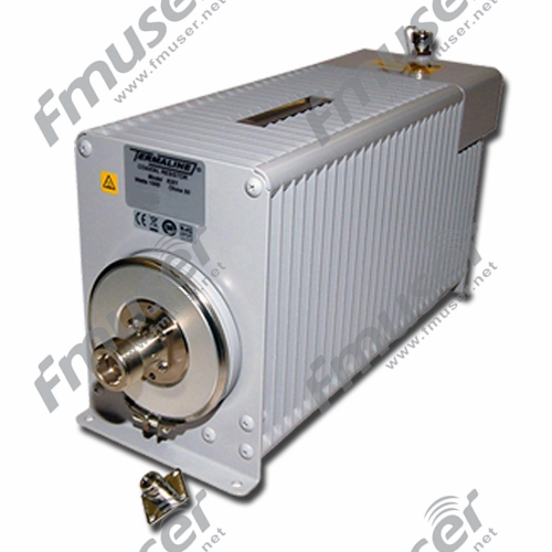
ਆਮ ਤੌਰ 'ਤੇ, ਇੱਕ ਡਮੀ ਲੋਡ ਵਿੱਚ ਇੱਕ ਰੇਡੀਏਟਰ ਨਾਲ ਜੁੜਿਆ ਇੱਕ ਰੋਧਕ ਹੁੰਦਾ ਹੈ ਜੋ ਕੁਸ਼ਲਤਾ ਨਾਲ ਟ੍ਰਾਂਸਮੀਟਰ ਤੋਂ ਪਾਵਰ ਨੂੰ ਦੂਰ ਕਰਦਾ ਹੈ, ਰੇਡੀਓ ਫ੍ਰੀਕੁਐਂਸੀ (RF) ਊਰਜਾ ਨੂੰ ਪ੍ਰਭਾਵਸ਼ਾਲੀ ਢੰਗ ਨਾਲ ਜਜ਼ਬ ਕਰਦਾ ਹੈ ਅਤੇ ਐਂਟੀਨਾ ਦੀਆਂ ਰੁਕਾਵਟਾਂ ਦੀਆਂ ਵਿਸ਼ੇਸ਼ਤਾਵਾਂ ਦੀ ਨਕਲ ਕਰਦਾ ਹੈ। RF ਲੋਡ ਜਾਂ ਸਮਾਪਤੀ ਲੋਡ ਵਜੋਂ ਜਾਣਿਆ ਜਾਂਦਾ ਹੈ, ਡਮੀ ਲੋਡ ਟ੍ਰਾਂਸਮੀਟਰ ਦੁਆਰਾ ਉਤਪੰਨ RF ਊਰਜਾ ਨੂੰ ਜਜ਼ਬ ਕਰਨ ਲਈ ਇੱਕ ਨਿਯੰਤਰਿਤ ਅਤੇ ਸੁਰੱਖਿਅਤ ਸਾਧਨ ਪ੍ਰਦਾਨ ਕਰਦੇ ਹਨ ਜਦੋਂ ਇੱਕ ਅਸਲ ਐਂਟੀਨਾ ਕਨੈਕਟ ਨਹੀਂ ਹੁੰਦਾ ਹੈ। ਇਹ ਨਾ ਸਿਰਫ ਵਾਤਾਵਰਣ ਵਿੱਚ ਬੇਲੋੜੀ ਰੇਡੀਏਸ਼ਨ ਨੂੰ ਰੋਕਦਾ ਹੈ ਬਲਕਿ ਇੱਕ ਬੇਮੇਲ ਜਾਂ ਅਣ-ਕੁਨੈਕਟਡ ਟ੍ਰਾਂਸਮਿਸ਼ਨ ਲਾਈਨ ਦੇ ਨਤੀਜੇ ਵਜੋਂ ਹੋਣ ਵਾਲੇ ਸੰਭਾਵੀ ਨੁਕਸਾਨ ਤੋਂ ਟ੍ਰਾਂਸਮੀਟਰ ਦੀ ਸੁਰੱਖਿਆ ਵੀ ਕਰਦਾ ਹੈ।

ਟਰਾਂਸਮੀਟਰ ਅਤੇ ਰਿਸੀਵਰ ਦੇ ਮਾਪਦੰਡਾਂ ਨੂੰ ਸਹੀ ਢੰਗ ਨਾਲ ਐਡਜਸਟ ਕਰਨ ਦੇ ਨਾਲ-ਨਾਲ, ਡਮੀ ਲੋਡ ਗਲਤ ਕੰਮ ਕਰਕੇ ਹੋਣ ਵਾਲੇ ਨੁਕਸਾਨ ਨੂੰ ਰੋਕਣ ਵਿੱਚ ਇੱਕ ਮਹੱਤਵਪੂਰਨ ਭੂਮਿਕਾ ਨਿਭਾਉਂਦਾ ਹੈ। ਆਰਐਫ ਇੰਜੀਨੀਅਰ ਡਮੀ ਲੋਡ ਨੂੰ ਐਂਪਲੀਫਾਇਰ ਜਾਂ ਆਰਐਫ ਪ੍ਰਣਾਲੀਆਂ ਦੀ ਜਾਂਚ ਕਰਨ ਲਈ ਸਾਜ਼ੋ-ਸਾਮਾਨ ਲੋਡ ਕਰਨ ਲਈ ਇੱਕ ਸਾਧਨ ਵਜੋਂ ਪਛਾਣਦੇ ਹਨ। ਬਿਨਾਂ ਕਿਸੇ ਲੋਡ ਦੇ, ਟੈਸਟਿੰਗ ਦੌਰਾਨ ਸਿੱਧੇ ਐਂਟੀਨਾ ਦੀ ਵਰਤੋਂ ਕਰਨਾ, ਨਾ ਸਿਰਫ਼ ਸੰਪੂਰਣ ਟਿਊਨਿੰਗ ਵਿੱਚ ਰੁਕਾਵਟ ਪਾਉਂਦਾ ਹੈ, ਸਗੋਂ RF ਪਾਵਰ ਦੁਆਰਾ ਉਤਪੰਨ ਗਰਮੀ ਦੇ ਕਾਰਨ ਟ੍ਰਾਂਸਮੀਟਰ ਜਾਂ ਰਿਸੀਵਰ ਨੂੰ ਨੁਕਸਾਨ ਪਹੁੰਚਾਉਣ ਦਾ ਜੋਖਮ ਵੀ ਹੁੰਦਾ ਹੈ। ਐਂਪਲੀਫਾਇਰ ਨਾਲ ਜੁੜੇ ਇੱਕ ਬਿਲਕੁਲ ਟਿਊਨਡ ਐਂਟੀਨਾ ਦੀ ਨਕਲ ਕਰਕੇ, ਡਮੀ ਲੋਡ ਗਲਤ ਪੈਰਾਮੀਟਰ ਸੈਟਿੰਗਾਂ ਜਾਂ RF ਉਪਕਰਣਾਂ ਨੂੰ ਨੁਕਸਾਨ ਤੋਂ ਬਚਾਉਂਦਾ ਹੈ। ਇਹ ਜ਼ੋਰਦਾਰ ਸਿਫਾਰਸ਼ ਕੀਤੀ ਜਾਂਦੀ ਹੈ ਕਿ ਇੱਕ ਭਰੋਸੇਯੋਗ ਡਮੀ ਲੋਡ ਚੁਣੋ ਅਤੇ ਬੇਲੋੜੇ ਨੁਕਸਾਨ ਨੂੰ ਘੱਟ ਕਰਨ ਲਈ RF ਸਾਜ਼ੋ-ਸਾਮਾਨ ਦੀ ਜਾਂਚ ਦੌਰਾਨ ਇਸਦੀ ਸਹੀ ਅਤੇ ਤੁਰੰਤ ਵਰਤੋਂ ਕਰੋ।
ਡਮੀ ਲੋਡ ਚੁਣਨਾ
ਡਮੀ ਲੋਡ ਦੀ ਚੋਣ ਕਰਦੇ ਸਮੇਂ ਹੇਠਾਂ ਦਿੱਤੇ ਕਾਰਕਾਂ 'ਤੇ ਗੌਰ ਕਰੋ:
- ਪਾਵਰ ਹੈਂਡਲਿੰਗ ਸਮਰੱਥਾ: ਡਮੀ ਲੋਡ ਦੀ ਪਾਵਰ ਹੈਂਡਲਿੰਗ ਸਮਰੱਥਾ ਦਾ ਪਤਾ ਲਗਾਓ। ਯਕੀਨੀ ਬਣਾਓ ਕਿ ਇਹ ਤੁਹਾਡੇ ਟ੍ਰਾਂਸਮੀਟਰ ਦੀ ਵੱਧ ਤੋਂ ਵੱਧ ਪਾਵਰ ਆਉਟਪੁੱਟ ਨੂੰ ਇਸਦੀ ਸੀਮਾ ਤੋਂ ਵੱਧ ਜਾਂ ਨੁਕਸਾਨ ਪਹੁੰਚਾਏ ਬਿਨਾਂ ਸੁਰੱਖਿਅਤ ਢੰਗ ਨਾਲ ਸੰਭਾਲ ਸਕਦਾ ਹੈ।
- ਇੰਪੀਡੈਂਸ ਮੈਚਿੰਗ: ਪੁਸ਼ਟੀ ਕਰੋ ਕਿ ਡਮੀ ਲੋਡ ਤੁਹਾਡੀ ਟਰਾਂਸਮਿਸ਼ਨ ਲਾਈਨ ਦੀ ਰੁਕਾਵਟ ਨਾਲ ਮੇਲ ਖਾਂਦਾ ਹੈ, ਆਮ ਤੌਰ 'ਤੇ 50 ਓਮ। ਇਹ ਰੁਕਾਵਟ ਮੇਲ ਇਹ ਯਕੀਨੀ ਬਣਾਉਂਦਾ ਹੈ ਕਿ ਟ੍ਰਾਂਸਮੀਟਰ ਸਹੀ ਢੰਗ ਨਾਲ ਕੰਮ ਕਰਦਾ ਹੈ ਅਤੇ ਪ੍ਰਤੀਬਿੰਬ ਨੂੰ ਘੱਟ ਕਰਦਾ ਹੈ।
- ਕੂਲਿੰਗ ਅਤੇ ਹੀਟ ਡਿਸਸੀਪੇਸ਼ਨ: ਨਕਲੀ ਲੋਡ ਦੇ ਕੂਲਿੰਗ ਮਕੈਨਿਜ਼ਮ ਅਤੇ ਗਰਮੀ ਦੀ ਖਰਾਬੀ ਦੀਆਂ ਸਮਰੱਥਾਵਾਂ 'ਤੇ ਵਿਚਾਰ ਕਰੋ। ਅਜਿਹੇ ਡਿਜ਼ਾਈਨਾਂ ਦੀ ਭਾਲ ਕਰੋ ਜੋ ਸਮਾਈ ਹੋਈ RF ਊਰਜਾ ਦੁਆਰਾ ਪੈਦਾ ਹੋਈ ਗਰਮੀ ਨੂੰ ਕੁਸ਼ਲਤਾ ਨਾਲ ਖਤਮ ਕਰਦੇ ਹਨ, ਇਹ ਯਕੀਨੀ ਬਣਾਉਂਦੇ ਹੋਏ ਕਿ ਡਮੀ ਲੋਡ ਸੁਰੱਖਿਅਤ ਓਪਰੇਟਿੰਗ ਤਾਪਮਾਨਾਂ ਦੇ ਅੰਦਰ ਬਣਿਆ ਰਹੇ।
- ਕਨੈਕਟੀਵਿਟੀ: ਪੁਸ਼ਟੀ ਕਰੋ ਕਿ ਡਮੀ ਲੋਡ ਵਿੱਚ ਤੁਹਾਡੀ ਟਰਾਂਸਮਿਸ਼ਨ ਲਾਈਨ ਨਾਲ ਮੇਲ ਕਰਨ ਲਈ ਢੁਕਵੇਂ ਕਨੈਕਟਰ ਹਨ। ਆਮ ਕਨੈਕਟਰਾਂ ਵਿੱਚ BNC, N-type, ਜਾਂ UHF ਕਨੈਕਟਰ ਸ਼ਾਮਲ ਹੁੰਦੇ ਹਨ।
- ਸ਼ੁੱਧਤਾ: ਇਹ ਯਕੀਨੀ ਬਣਾਉਣ ਲਈ ਕਿ ਇਹ ਐਂਟੀਨਾ ਦੇ ਲੋਡ ਦਾ ਇੱਕ ਭਰੋਸੇਯੋਗ ਸਿਮੂਲੇਸ਼ਨ ਪ੍ਰਦਾਨ ਕਰਦਾ ਹੈ, ਡਮੀ ਲੋਡ ਦੇ ਅੜਿੱਕਾ ਮਿਲਾਨ ਦੀ ਸ਼ੁੱਧਤਾ ਦਾ ਮੁਲਾਂਕਣ ਕਰੋ। ਡਮੀ ਲੋਡਾਂ ਦੀ ਭਾਲ ਕਰੋ ਜਿਨ੍ਹਾਂ ਦੀ ਜਾਂਚ ਕੀਤੀ ਗਈ ਹੈ ਅਤੇ ਉਹਨਾਂ ਦੀਆਂ ਰੁਕਾਵਟਾਂ ਦੀਆਂ ਵਿਸ਼ੇਸ਼ਤਾਵਾਂ ਲਈ ਪ੍ਰਮਾਣਿਤ ਕੀਤਾ ਗਿਆ ਹੈ।
ਤੁਹਾਡੇ ਲਈ ਸਿਫ਼ਾਰਸ਼ੀ ਹਾਈ ਪਾਵਰ ਆਰਐਫ ਡਮੀ ਲੋਡ


AM ਨਕਲੀ ਲੋਡ
AM ਨਕਲੀ ਲੋਡ AM ਪ੍ਰਸਾਰਣ ਵਿੱਚ ਇੱਕ ਐਂਟੀਨਾ ਸਿਸਟਮ ਦੀ ਰੁਕਾਵਟ ਨਾਲ ਮੇਲ ਕਰਨ ਲਈ ਤਿਆਰ ਕੀਤੇ ਗਏ ਰੋਧਕ ਲੋਡ ਹਨ। ਇਹਨਾਂ ਵਿੱਚ ਇੱਕ ਤਾਪ-ਘਟਾਉਣ ਵਾਲੇ ਘੇਰੇ ਵਿੱਚ ਬੰਦ ਰੋਧਕ ਤੱਤ ਹੁੰਦੇ ਹਨ। ਨਕਲੀ ਲੋਡ ਆਮ ਤੌਰ 'ਤੇ ਸਾਜ਼ੋ-ਸਾਮਾਨ ਦੀ ਜਾਂਚ, ਟ੍ਰਾਂਸਮੀਟਰ ਰੱਖ-ਰਖਾਅ, ਜਾਂ ਜਦੋਂ ਸਿਗਨਲ ਟ੍ਰਾਂਸਮਿਸ਼ਨ ਲਈ ਅਸਲ ਐਂਟੀਨਾ ਲੋੜੀਂਦਾ ਜਾਂ ਸੰਭਵ ਨਹੀਂ ਹੁੰਦਾ ਹੈ ਤਾਂ ਵਰਤਿਆ ਜਾਂਦਾ ਹੈ।

AM ਡਮੀ ਲੋਡ ਕਿਵੇਂ ਕੰਮ ਕਰਦੇ ਹਨ?
AM ਡਮੀ ਲੋਡ ਇੱਕ ਪ੍ਰਤੀਰੋਧਕ ਲੋਡ ਪ੍ਰਦਾਨ ਕਰਕੇ ਕੰਮ ਕਰਦੇ ਹਨ ਜੋ ਐਂਟੀਨਾ ਸਿਸਟਮ ਦੀ ਰੁਕਾਵਟ ਨਾਲ ਮੇਲ ਖਾਂਦਾ ਹੈ, ਆਮ ਤੌਰ 'ਤੇ 50 ਜਾਂ 75 ਓਮ। ਉਹ ਟ੍ਰਾਂਸਮੀਟਰ ਤੋਂ ਆਰਐਫ ਪਾਵਰ ਨੂੰ ਜਜ਼ਬ ਕਰ ਲੈਂਦੇ ਹਨ, ਇਸਨੂੰ ਹਵਾ ਵਿੱਚ ਰੇਡੀਏਟ ਹੋਣ ਤੋਂ ਰੋਕਦੇ ਹਨ। ਡਮੀ ਲੋਡ ਦੇ ਅੰਦਰ ਰੋਧਕ ਤੱਤ RF ਊਰਜਾ ਨੂੰ ਗਰਮੀ ਵਿੱਚ ਬਦਲਦੇ ਹਨ, ਜਿਸਨੂੰ ਫਿਰ ਹੀਟ ਸਿੰਕ ਜਾਂ ਕੂਲਿੰਗ ਵਿਧੀ ਦੀ ਵਰਤੋਂ ਕਰਕੇ ਖਤਮ ਕੀਤਾ ਜਾਂਦਾ ਹੈ।
ਸਮਾਈ ਹੋਈ ਸ਼ਕਤੀ ਨੂੰ ਗਰਮੀ ਦੇ ਰੂਪ ਵਿੱਚ ਖਤਮ ਕਰ ਦਿੱਤਾ ਜਾਂਦਾ ਹੈ, ਅਤੇ ਡਮੀ ਲੋਡ ਨੂੰ ਓਵਰਹੀਟਿੰਗ ਜਾਂ ਨੁਕਸਾਨ ਤੋਂ ਬਿਨਾਂ ਟ੍ਰਾਂਸਮੀਟਰ ਦੁਆਰਾ ਪੈਦਾ ਕੀਤੇ ਪਾਵਰ ਪੱਧਰਾਂ ਨੂੰ ਸੰਭਾਲਣ ਲਈ ਤਿਆਰ ਕੀਤਾ ਜਾਣਾ ਚਾਹੀਦਾ ਹੈ। ਇਹ ਯਕੀਨੀ ਬਣਾਉਣ ਲਈ ਕਿ ਇਹ ਟੈਸਟ ਕੀਤੇ ਜਾ ਰਹੇ ਟਰਾਂਸਮੀਟਰ ਦੀ ਪਾਵਰ ਰੇਟਿੰਗ ਨੂੰ ਸੰਭਾਲ ਸਕਦਾ ਹੈ, ਡਮੀ ਲੋਡ ਦੀ ਗਰਮੀ ਡਿਸਸੀਪੇਸ਼ਨ ਸਮਰੱਥਾ 'ਤੇ ਵਿਚਾਰ ਕੀਤਾ ਜਾਣਾ ਚਾਹੀਦਾ ਹੈ।
AM ਡਮੀ ਲੋਡ ਚੁਣਨਾ
AM ਡਮੀ ਲੋਡ ਦੀ ਚੋਣ ਕਰਦੇ ਸਮੇਂ ਹੇਠਾਂ ਦਿੱਤੇ ਕਾਰਕਾਂ 'ਤੇ ਗੌਰ ਕਰੋ:
- ਪ੍ਰਤੀਬਿੰਬਤ: ਤੁਹਾਡੀ ਅਰਜ਼ੀ ਲਈ ਲੋੜੀਂਦੀ ਪ੍ਰਤੀਰੋਧ ਰੇਟਿੰਗ ਨਿਰਧਾਰਤ ਕਰੋ। ਇੱਕ AM ਡਮੀ ਲੋਡ ਚੁਣੋ ਜੋ ਤੁਹਾਡੇ ਐਂਟੀਨਾ ਸਿਸਟਮ ਦੀ ਰੁਕਾਵਟ (ਆਮ ਤੌਰ 'ਤੇ 50 ਜਾਂ 75 ohms) ਨਾਲ ਮੇਲ ਖਾਂਦਾ ਹੋਵੇ ਤਾਂ ਜੋ ਸਹੀ ਟੈਸਟਿੰਗ ਅਤੇ ਮਾਪ ਦੇ ਨਤੀਜਿਆਂ ਨੂੰ ਯਕੀਨੀ ਬਣਾਇਆ ਜਾ ਸਕੇ।
- ਪਾਵਰ ਹੈਂਡਲਿੰਗ ਸਮਰੱਥਾ: ਪੁਸ਼ਟੀ ਕਰੋ ਕਿ ਡਮੀ ਲੋਡ ਤੁਹਾਡੇ ਟ੍ਰਾਂਸਮੀਟਰ ਦੀ ਪਾਵਰ ਰੇਟਿੰਗ ਨੂੰ ਸੰਭਾਲ ਸਕਦਾ ਹੈ। ਆਪਣੇ ਟ੍ਰਾਂਸਮੀਟਰ ਦੀ ਵੱਧ ਤੋਂ ਵੱਧ ਪਾਵਰ ਆਉਟਪੁੱਟ 'ਤੇ ਵਿਚਾਰ ਕਰੋ ਅਤੇ ਇੱਕ ਪਾਵਰ ਰੇਟਿੰਗ ਵਾਲਾ ਇੱਕ ਡਮੀ ਲੋਡ ਚੁਣੋ ਜੋ ਸੁਰੱਖਿਅਤ ਅਤੇ ਭਰੋਸੇਮੰਦ ਸੰਚਾਲਨ ਨੂੰ ਯਕੀਨੀ ਬਣਾਉਣ ਲਈ ਤੁਹਾਡੇ ਟ੍ਰਾਂਸਮੀਟਰ ਦੀ ਅਧਿਕਤਮ ਸ਼ਕਤੀ ਤੋਂ ਵੱਧ ਹੋਵੇ।
- ਤਾਪ ਦਾ ਨਿਕਾਸ: ਇਹ ਸੁਨਿਸ਼ਚਿਤ ਕਰੋ ਕਿ ਡਮੀ ਲੋਡ ਨੂੰ ਸਮਾਈ ਜਾ ਰਹੀ ਸ਼ਕਤੀ ਨੂੰ ਸੰਭਾਲਣ ਲਈ ਢੁਕਵੀਂ ਤਾਪ ਵਿਘਨ ਵਿਧੀ ਨਾਲ ਤਿਆਰ ਕੀਤਾ ਗਿਆ ਹੈ। ਗਰਮੀ ਨੂੰ ਪ੍ਰਭਾਵਸ਼ਾਲੀ ਢੰਗ ਨਾਲ ਖਤਮ ਕਰਨ ਅਤੇ ਜ਼ਿਆਦਾ ਗਰਮ ਹੋਣ ਤੋਂ ਰੋਕਣ ਲਈ ਕੂਲਿੰਗ ਫਿਨਸ, ਹੀਟ ਸਿੰਕ ਜਾਂ ਪੱਖੇ ਵਰਗੇ ਕਾਰਕਾਂ 'ਤੇ ਵਿਚਾਰ ਕਰੋ।
- ਨਿਰਮਾਣ ਗੁਣ: ਲੰਬੀ ਉਮਰ ਅਤੇ ਸ਼ੁੱਧਤਾ ਨੂੰ ਯਕੀਨੀ ਬਣਾਉਣ ਲਈ ਇੱਕ ਚੰਗੀ ਤਰ੍ਹਾਂ ਤਿਆਰ ਅਤੇ ਭਰੋਸੇਮੰਦ ਡਮੀ ਲੋਡ ਚੁਣੋ। ਟੈਸਟਿੰਗ ਜਾਂ ਪ੍ਰਸਾਰਣ ਦੌਰਾਨ ਇੱਕ ਸੁਰੱਖਿਅਤ ਅਤੇ ਸਥਿਰ ਕੁਨੈਕਸ਼ਨ ਨੂੰ ਯਕੀਨੀ ਬਣਾਉਣ ਲਈ ਮਜ਼ਬੂਤ ਉਸਾਰੀ, ਟਿਕਾਊ ਸਮੱਗਰੀ ਅਤੇ ਉਚਿਤ ਕੁਨੈਕਸ਼ਨਾਂ ਦੀ ਭਾਲ ਕਰੋ।
- ਬਾਰੰਬਾਰਤਾ ਸੀਮਾ: ਪੁਸ਼ਟੀ ਕਰੋ ਕਿ ਡਮੀ ਲੋਡ ਤੁਹਾਡੇ AM ਪ੍ਰਸਾਰਣ ਸਿਸਟਮ ਵਿੱਚ ਵਰਤੀ ਗਈ ਬਾਰੰਬਾਰਤਾ ਸੀਮਾ ਨੂੰ ਕਵਰ ਕਰਦਾ ਹੈ। ਇਹ ਸੁਨਿਸ਼ਚਿਤ ਕਰੋ ਕਿ ਇਹ ਤੁਹਾਡੀ ਐਪਲੀਕੇਸ਼ਨ ਦੀ ਖਾਸ ਬਾਰੰਬਾਰਤਾ ਰੇਂਜ ਨੂੰ ਮਹੱਤਵਪੂਰਣ ਰੁਕਾਵਟਾਂ ਦੇ ਭਿੰਨਤਾਵਾਂ ਤੋਂ ਬਿਨਾਂ ਹੈਂਡਲ ਕਰ ਸਕਦਾ ਹੈ।
ਤੁਹਾਡੇ ਲਈ AM ਡਮੀ ਲੋਡ ਦੀ ਸਿਫ਼ਾਰਿਸ਼ ਕੀਤੀ ਗਈ
 |
 |
 |
| 1/3/5 ਕਿਲੋਵਾਟ | 100 ਕੇਡਬਲਯੂ | 200 ਕੇਡਬਲਯੂ |
ਆਰਐਫ ਪਾਵਰ ਐਂਪਲੀਫਾਇਰ ਵੋਲਟੇਜ ਟੈਸਟ ਬੈਂਚ
ਇੱਕ RF ਪਾਵਰ ਐਂਪਲੀਫਾਇਰ ਵੋਲਟੇਜ ਟੈਸਟ ਬੈਂਚ ਇੱਕ ਸਮਰਪਿਤ ਸੈੱਟਅੱਪ ਹੈ ਜੋ ਖਾਸ ਤੌਰ 'ਤੇ AM ਟ੍ਰਾਂਸਮੀਟਰਾਂ ਵਿੱਚ ਵਰਤੇ ਜਾਣ ਵਾਲੇ RF ਪਾਵਰ ਐਂਪਲੀਫਾਇਰ ਦੀ ਕਾਰਗੁਜ਼ਾਰੀ ਦੀ ਜਾਂਚ ਅਤੇ ਵਿਸ਼ਲੇਸ਼ਣ ਲਈ ਤਿਆਰ ਕੀਤਾ ਗਿਆ ਹੈ। ਇਹ ਇੰਜੀਨੀਅਰਾਂ ਅਤੇ ਤਕਨੀਸ਼ੀਅਨਾਂ ਨੂੰ ਐਂਪਲੀਫਾਇਰ ਦੀ ਕੁਸ਼ਲਤਾ, ਰੇਖਿਕਤਾ, ਵਿਗਾੜ ਅਤੇ ਹੋਰ ਜ਼ਰੂਰੀ ਮਾਪਦੰਡਾਂ ਦਾ ਮੁਲਾਂਕਣ ਕਰਨ ਦੀ ਆਗਿਆ ਦਿੰਦਾ ਹੈ।

* FMUSER ਤੋਂ ਆਰਐਫ ਪਾਵਰ ਐਂਪਲੀਫਾਇਰ ਵੋਲਟੇਜ ਟੈਸਟ ਬੈਂਚ, ਹੋਰ ਜਾਣੋ:
https://www.fmradiobroadcast.com/product/detail/am-transmitter-test-bench.html
ਇੱਕ ਆਰਐਫ ਪਾਵਰ ਐਂਪਲੀਫਾਇਰ ਵੋਲਟੇਜ ਟੈਸਟ ਬੈਂਚ ਕਿਵੇਂ ਕੰਮ ਕਰਦਾ ਹੈ?
ਇੱਕ ਆਰਐਫ ਪਾਵਰ ਐਂਪਲੀਫਾਇਰ ਵੋਲਟੇਜ ਟੈਸਟ ਬੈਂਚ ਵਿੱਚ ਆਮ ਤੌਰ 'ਤੇ ਆਰਐਫ ਪਾਵਰ ਐਂਪਲੀਫਾਇਰ ਦੀ ਸਹੀ ਜਾਂਚ ਅਤੇ ਮਾਪ ਦੀ ਸਹੂਲਤ ਲਈ ਵੱਖ-ਵੱਖ ਉਪਕਰਣ ਅਤੇ ਹਿੱਸੇ ਹੁੰਦੇ ਹਨ। ਟੈਸਟ ਬੈਂਚ ਵਿੱਚ ਸ਼ਾਮਲ ਹੋ ਸਕਦੇ ਹਨ:
- ਸਿਗਨਲ ਜਨਰੇਟਰ: ਟੈਸਟ ਦੇ ਅਧੀਨ ਪਾਵਰ ਐਂਪਲੀਫਾਇਰ ਨੂੰ ਇੰਪੁੱਟ ਸਿਗਨਲ ਪ੍ਰਦਾਨ ਕਰਦਾ ਹੈ। ਸਿਗਨਲ ਜਨਰੇਟਰ ਲੋੜੀਂਦੀ ਬਾਰੰਬਾਰਤਾ ਅਤੇ ਪਾਵਰ ਪੱਧਰ 'ਤੇ ਮੋਡਿਊਲੇਟਡ ਜਾਂ ਅਨਮੋਡਿਊਲਡ ਆਰਐਫ ਸਿਗਨਲ ਤਿਆਰ ਕਰਦਾ ਹੈ।
- ਪਾਵਰ ਮੀਟਰ: ਟੈਸਟ ਕੀਤੇ ਜਾ ਰਹੇ ਐਂਪਲੀਫਾਇਰ ਦੀ ਆਉਟਪੁੱਟ ਪਾਵਰ ਨੂੰ ਮਾਪਦਾ ਹੈ। ਇਹ ਵੱਖ-ਵੱਖ ਬਾਰੰਬਾਰਤਾ ਬੈਂਡਾਂ ਲਈ ਸਹੀ ਪਾਵਰ ਮਾਪ ਪ੍ਰਦਾਨ ਕਰਦਾ ਹੈ ਅਤੇ ਐਂਪਲੀਫਾਇਰ ਦੀ ਕਾਰਗੁਜ਼ਾਰੀ ਅਤੇ ਰੇਖਿਕਤਾ ਦਾ ਮੁਲਾਂਕਣ ਕਰਨ ਵਿੱਚ ਮਦਦ ਕਰਦਾ ਹੈ।
- ਲੋਡ ਸਮਾਪਤੀ: ਇੱਕ ਲੋਡ ਸਮਾਪਤੀ ਪਾਵਰ ਐਂਪਲੀਫਾਇਰ ਦੇ ਆਉਟਪੁੱਟ ਨਾਲ ਮੇਲ ਖਾਂਦਾ ਲੋਡ ਪ੍ਰਦਾਨ ਕਰਨ ਅਤੇ ਸਹੀ ਟੈਸਟਿੰਗ ਸਥਿਤੀਆਂ ਨੂੰ ਯਕੀਨੀ ਬਣਾਉਣ ਲਈ ਜੁੜਿਆ ਹੋਇਆ ਹੈ। ਇਹ ਐਂਪਲੀਫਾਇਰ ਦੁਆਰਾ ਤਿਆਰ ਕੀਤੀ ਆਉਟਪੁੱਟ ਪਾਵਰ ਨੂੰ ਇਸ ਨੂੰ ਪਿੱਛੇ ਪ੍ਰਤੀਬਿੰਬਤ ਕੀਤੇ ਬਿਨਾਂ ਅਤੇ ਦਖਲਅੰਦਾਜ਼ੀ ਜਾਂ ਨੁਕਸਾਨ ਪਹੁੰਚਾਉਣ ਵਿੱਚ ਮਦਦ ਕਰਦਾ ਹੈ।
- ਟੈਸਟ ਸਿਗਨਲ ਨਿਗਰਾਨੀ: ਔਸਿਲੋਸਕੋਪ ਜਾਂ ਸਪੈਕਟ੍ਰਮ ਵਿਸ਼ਲੇਸ਼ਕ ਵਰਗੇ ਉਪਕਰਨਾਂ ਦੀ ਵਰਤੋਂ ਆਉਟਪੁੱਟ ਸਿਗਨਲ ਗੁਣਵੱਤਾ, ਵਿਗਾੜ ਅਤੇ ਹੋਰ ਵਿਸ਼ੇਸ਼ਤਾਵਾਂ ਦੀ ਨਿਗਰਾਨੀ ਅਤੇ ਵਿਸ਼ਲੇਸ਼ਣ ਕਰਨ ਲਈ ਕੀਤੀ ਜਾ ਸਕਦੀ ਹੈ।
ਆਰਐਫ ਪਾਵਰ ਐਂਪਲੀਫਾਇਰ ਵੋਲਟੇਜ ਟੈਸਟ ਬੈਂਚ ਇੰਜੀਨੀਅਰਾਂ ਨੂੰ ਨਿਯੰਤਰਿਤ ਇਨਪੁਟ ਸਿਗਨਲਾਂ ਨੂੰ ਲਾਗੂ ਕਰਨ, ਆਉਟਪੁੱਟ ਪਾਵਰ ਨੂੰ ਮਾਪਣ, ਸਿਗਨਲ ਗੁਣਵੱਤਾ ਦਾ ਵਿਸ਼ਲੇਸ਼ਣ ਕਰਨ, ਅਤੇ ਵੱਖ-ਵੱਖ ਓਪਰੇਟਿੰਗ ਹਾਲਤਾਂ ਅਧੀਨ ਪਾਵਰ ਐਂਪਲੀਫਾਇਰ ਦੀ ਕਾਰਗੁਜ਼ਾਰੀ ਦਾ ਮੁਲਾਂਕਣ ਕਰਨ ਦੀ ਆਗਿਆ ਦਿੰਦਾ ਹੈ।
ਇੱਕ ਆਰਐਫ ਪਾਵਰ ਐਂਪਲੀਫਾਇਰ ਵੋਲਟੇਜ ਟੈਸਟ ਬੈਂਚ ਚੁਣਨਾ
RF ਪਾਵਰ ਐਂਪਲੀਫਾਇਰ ਵੋਲਟੇਜ ਟੈਸਟ ਬੈਂਚ ਦੀ ਚੋਣ ਕਰਦੇ ਸਮੇਂ ਹੇਠਾਂ ਦਿੱਤੇ ਕਾਰਕਾਂ 'ਤੇ ਗੌਰ ਕਰੋ:
- ਅਨੁਕੂਲਤਾ: ਯਕੀਨੀ ਬਣਾਓ ਕਿ ਟੈਸਟ ਬੈਂਚ ਤੁਹਾਡੇ AM ਟ੍ਰਾਂਸਮੀਟਰਾਂ ਵਿੱਚ ਵਰਤੇ ਜਾਂਦੇ RF ਪਾਵਰ ਐਂਪਲੀਫਾਇਰ ਦੀ ਖਾਸ ਕਿਸਮ ਅਤੇ ਬਾਰੰਬਾਰਤਾ ਸੀਮਾ ਦੇ ਅਨੁਕੂਲ ਹੈ।
- ਪਾਵਰ ਹੈਂਡਲਿੰਗ ਸਮਰੱਥਾ: ਜਾਂਚ ਕਰੋ ਕਿ ਟੈਸਟ ਬੈਂਚ ਟੈਸਟ ਕੀਤੇ ਜਾ ਰਹੇ ਐਂਪਲੀਫਾਇਰਾਂ ਦੀ ਵੱਧ ਤੋਂ ਵੱਧ ਆਉਟਪੁੱਟ ਪਾਵਰ ਨੂੰ ਅਨੁਕੂਲ ਕਰਨ ਲਈ ਲੋੜੀਂਦੀ ਪਾਵਰ ਹੈਂਡਲਿੰਗ ਸਮਰੱਥਾ ਪ੍ਰਦਾਨ ਕਰਦਾ ਹੈ। ਇਹ ਬਿਨਾਂ ਕਿਸੇ ਵਿਗਾੜ ਜਾਂ ਨੁਕਸਾਨ ਦੇ ਪਾਵਰ ਪੱਧਰਾਂ ਨੂੰ ਸੰਭਾਲਣ ਦੇ ਯੋਗ ਹੋਣਾ ਚਾਹੀਦਾ ਹੈ।
- ਮਾਪਣ ਦੀ ਸਹੀਤਾ: ਟੈਸਟ ਬੈਂਚ ਦੇ ਪਾਵਰ ਮੀਟਰ ਜਾਂ ਹੋਰ ਮਾਪ ਉਪਕਰਣ ਦੀ ਮਾਪ ਸ਼ੁੱਧਤਾ 'ਤੇ ਵਿਚਾਰ ਕਰੋ। ਐਂਪਲੀਫਾਇਰ ਪ੍ਰਦਰਸ਼ਨ ਦੇ ਮੁਲਾਂਕਣ ਅਤੇ ਤੁਲਨਾ ਕਰਨ ਲਈ ਸਹੀ ਮਾਪ ਮਹੱਤਵਪੂਰਨ ਹਨ।
- ਵਰਤੋਂ ਅਤੇ ਨਿਯੰਤਰਣ ਦੀ ਸੌਖ: ਇੱਕ ਟੈਸਟ ਬੈਂਚ ਦੀ ਭਾਲ ਕਰੋ ਜੋ ਉਪਭੋਗਤਾ-ਅਨੁਕੂਲ ਨਿਯੰਤਰਣ ਅਤੇ ਆਸਾਨ ਸੰਚਾਲਨ ਲਈ ਇੱਕ ਅਨੁਭਵੀ ਇੰਟਰਫੇਸ ਦੀ ਪੇਸ਼ਕਸ਼ ਕਰਦਾ ਹੈ। ਰਿਮੋਟ ਕੰਟਰੋਲ ਸਮਰੱਥਾਵਾਂ ਟੈਸਟਿੰਗ ਅਤੇ ਡਾਟਾ ਪ੍ਰਾਪਤੀ ਨੂੰ ਸੁਚਾਰੂ ਬਣਾਉਣ ਲਈ ਵੀ ਲਾਭਦਾਇਕ ਹੋ ਸਕਦੀਆਂ ਹਨ।
- ਵਿਸਤਾਰਯੋਗਤਾ ਅਤੇ ਲਚਕਤਾ: ਟੈਸਟ ਬੈਂਚ ਦੀਆਂ ਸਮਰੱਥਾਵਾਂ ਦਾ ਵਿਸਤਾਰ ਕਰਨ ਜਾਂ ਇਸ ਨੂੰ ਭਵਿੱਖ ਦੀਆਂ ਲੋੜਾਂ ਮੁਤਾਬਕ ਢਾਲਣ ਦੀ ਯੋਗਤਾ 'ਤੇ ਵਿਚਾਰ ਕਰੋ। ਟੈਸਟ ਬੈਂਚ ਨੂੰ ਵਿਕਾਸਸ਼ੀਲ ਟੈਸਟਿੰਗ ਲੋੜਾਂ ਨੂੰ ਪੂਰਾ ਕਰਨ ਲਈ ਭਵਿੱਖ ਦੇ ਅੱਪਗਰੇਡ ਜਾਂ ਸੋਧਾਂ ਦੀ ਇਜਾਜ਼ਤ ਦੇਣੀ ਚਾਹੀਦੀ ਹੈ।
ਆਰਐਫ ਪਾਵਰ ਮੀਟਰ
ਇੱਕ RF ਪਾਵਰ ਮੀਟਰ ਇੱਕ ਮਾਪਣ ਵਾਲਾ ਯੰਤਰ ਹੈ ਜੋ RF ਸਿਗਨਲਾਂ ਦੇ ਪਾਵਰ ਪੱਧਰ ਨੂੰ ਮਾਪਣ ਲਈ ਵਰਤਿਆ ਜਾਂਦਾ ਹੈ। ਇਹ ਆਮ ਤੌਰ 'ਤੇ ਰੇਡੀਓ ਪ੍ਰਸਾਰਣ, ਦੂਰਸੰਚਾਰ, ਵਾਇਰਲੈੱਸ ਪ੍ਰਣਾਲੀਆਂ, ਅਤੇ ਆਰਐਫ ਟੈਸਟਿੰਗ ਸਮੇਤ ਵੱਖ-ਵੱਖ ਐਪਲੀਕੇਸ਼ਨਾਂ ਵਿੱਚ ਵਰਤਿਆ ਜਾਂਦਾ ਹੈ। RF ਪਾਵਰ ਮੀਟਰ ਸਹੀ ਪਾਵਰ ਮਾਪ ਪ੍ਰਦਾਨ ਕਰਦੇ ਹਨ, ਖਾਸ ਤੌਰ 'ਤੇ ਵਾਟਸ ਜਾਂ ਡੈਸੀਬਲਾਂ ਵਿੱਚ, ਉਪਭੋਗਤਾਵਾਂ ਨੂੰ RF ਸਿਸਟਮਾਂ ਦੀ ਕਾਰਗੁਜ਼ਾਰੀ ਦਾ ਵਿਸ਼ਲੇਸ਼ਣ ਅਤੇ ਅਨੁਕੂਲਿਤ ਕਰਨ ਦੇ ਯੋਗ ਬਣਾਉਂਦੇ ਹਨ।

* FMUSER ਤੋਂ PM-1A RF ਪਾਵਰ ਮੀਟਰ, ਹੋਰ ਜਾਣੋ:
https://www.fmradiobroadcast.com/product/detail/pm1a-rf-power-meter.html
ਇੱਕ RF ਪਾਵਰ ਮੀਟਰ ਕਿਵੇਂ ਕੰਮ ਕਰਦਾ ਹੈ?
RF ਪਾਵਰ ਮੀਟਰ ਆਮ ਤੌਰ 'ਤੇ RF ਸਿਗਨਲਾਂ ਦੀ ਸ਼ਕਤੀ ਨੂੰ ਮਾਪਣ ਲਈ ਵੱਖ-ਵੱਖ ਤਕਨੀਕਾਂ ਦੀ ਵਰਤੋਂ ਕਰਦੇ ਹਨ। ਵਰਤਿਆ ਜਾਣ ਵਾਲਾ ਖਾਸ ਤਰੀਕਾ ਬਾਰੰਬਾਰਤਾ ਸੀਮਾ, ਪਾਵਰ ਪੱਧਰ, ਅਤੇ ਸ਼ੁੱਧਤਾ ਲੋੜਾਂ 'ਤੇ ਨਿਰਭਰ ਕਰ ਸਕਦਾ ਹੈ। ਇੱਥੇ ਕੁਝ ਆਮ ਮਾਪ ਤਕਨੀਕ ਹਨ:
- ਥਰਮਲ ਪਾਵਰ ਸੈਂਸਰ: RF ਸਿਗਨਲ ਦੀ ਸ਼ਕਤੀ ਨੂੰ ਮਾਪਣ ਲਈ ਥਰਮੋਕੋਪਲ ਜਾਂ ਥਰਮਿਸਟਰ-ਅਧਾਰਿਤ ਸੈਂਸਰ ਦੀ ਵਰਤੋਂ ਕਰੋ। ਸੈਂਸਰ ਦੁਆਰਾ ਸਮਾਈ ਹੋਈ ਸ਼ਕਤੀ ਗਰਮੀ ਪੈਦਾ ਕਰਦੀ ਹੈ, ਜੋ ਕਿ ਆਰਐਫ ਪਾਵਰ ਦੇ ਅਨੁਪਾਤੀ ਇਲੈਕਟ੍ਰੀਕਲ ਸਿਗਨਲ ਵਿੱਚ ਬਦਲ ਜਾਂਦੀ ਹੈ।
- ਡਾਇਡ ਪਾਵਰ ਸੈਂਸਰ: ਇੱਕ ਡਾਇਓਡ-ਅਧਾਰਿਤ ਸੈਂਸਰ ਸ਼ਾਮਲ ਕਰੋ ਜੋ RF ਸਿਗਨਲ ਨੂੰ ਠੀਕ ਕਰਦਾ ਹੈ, ਇਸਨੂੰ RF ਪਾਵਰ ਪੱਧਰ ਦੇ ਅਨੁਪਾਤੀ ਇੱਕ DC ਵੋਲਟੇਜ ਵਿੱਚ ਬਦਲਦਾ ਹੈ। ਡਾਇਓਡ ਸੈਂਸਰ ਅਕਸਰ ਫ੍ਰੀਕੁਐਂਸੀ ਅਤੇ ਪਾਵਰ ਪੱਧਰਾਂ ਦੀ ਵਿਸ਼ਾਲ ਸ਼੍ਰੇਣੀ ਲਈ ਵਰਤੇ ਜਾਂਦੇ ਹਨ।
- RF ਫੀਲਡ ਤਾਕਤ ਮਾਪ: ਕੁਝ ਪਾਵਰ ਮੀਟਰ ਫੀਲਡ ਤਾਕਤ ਮਾਪ ਦੇ ਅਧਾਰ ਤੇ ਕੰਮ ਕਰਦੇ ਹਨ। ਉਹ RF ਸਿਗਨਲ ਦੀ ਇਲੈਕਟ੍ਰਿਕ ਜਾਂ ਚੁੰਬਕੀ ਖੇਤਰ ਦੀ ਤਾਕਤ ਨੂੰ ਮਾਪਣ ਲਈ ਐਂਟੀਨਾ ਜਾਂ ਪੜਤਾਲਾਂ ਦੀ ਵਰਤੋਂ ਕਰਦੇ ਹਨ। ਫੀਲਡ ਤਾਕਤ ਨੂੰ ਮਾਪ ਕੇ, ਐਂਟੀਨਾ ਦੀਆਂ ਵਿਸ਼ੇਸ਼ਤਾਵਾਂ ਬਾਰੇ ਖਾਸ ਫਾਰਮੂਲੇ ਅਤੇ ਧਾਰਨਾਵਾਂ ਦੀ ਵਰਤੋਂ ਕਰਕੇ ਸ਼ਕਤੀ ਦੀ ਗਣਨਾ ਕੀਤੀ ਜਾ ਸਕਦੀ ਹੈ।
RF ਪਾਵਰ ਮੀਟਰਾਂ ਵਿੱਚ RF ਸਿਗਨਲਾਂ ਦਾ ਵਧੇਰੇ ਵਿਆਪਕ ਵਿਸ਼ਲੇਸ਼ਣ ਪ੍ਰਦਾਨ ਕਰਨ ਲਈ ਬਾਰੰਬਾਰਤਾ ਮਾਪ, ਮੋਡੂਲੇਸ਼ਨ ਵਿਸ਼ਲੇਸ਼ਣ, ਅਤੇ ਡੇਟਾ ਲੌਗਿੰਗ ਵਰਗੀਆਂ ਵਾਧੂ ਸਮਰੱਥਾਵਾਂ ਵੀ ਸ਼ਾਮਲ ਹੋ ਸਕਦੀਆਂ ਹਨ।
ਇੱਕ RF ਪਾਵਰ ਮੀਟਰ ਚੁਣਨਾ
RF ਪਾਵਰ ਮੀਟਰ ਦੀ ਚੋਣ ਕਰਦੇ ਸਮੇਂ ਹੇਠਾਂ ਦਿੱਤੇ ਕਾਰਕਾਂ 'ਤੇ ਗੌਰ ਕਰੋ:
- ਬਾਰੰਬਾਰਤਾ ਸੀਮਾ: ਯਕੀਨੀ ਬਣਾਓ ਕਿ RF ਪਾਵਰ ਮੀਟਰ ਤੁਹਾਡੀਆਂ ਖਾਸ ਐਪਲੀਕੇਸ਼ਨਾਂ ਲਈ ਲੋੜੀਂਦੀ ਬਾਰੰਬਾਰਤਾ ਸੀਮਾ ਨੂੰ ਕਵਰ ਕਰਦਾ ਹੈ। ਇਹ ਉਹਨਾਂ ਬਾਰੰਬਾਰਤਾਵਾਂ ਦੇ ਅਨੁਕੂਲ ਹੋਣਾ ਚਾਹੀਦਾ ਹੈ ਜੋ ਤੁਸੀਂ ਮਾਪਣ ਦਾ ਇਰਾਦਾ ਰੱਖਦੇ ਹੋ।
- ਪਾਵਰ ਮਾਪ ਸੀਮਾ: ਤਸਦੀਕ ਕਰੋ ਕਿ ਪਾਵਰ ਮੀਟਰ ਪਾਵਰ ਦੇ ਪੱਧਰਾਂ ਨੂੰ ਅਨੁਕੂਲ ਕਰਨ ਲਈ ਇੱਕ ਢੁਕਵੀਂ ਪਾਵਰ ਮਾਪ ਰੇਂਜ ਦੀ ਪੇਸ਼ਕਸ਼ ਕਰਦਾ ਹੈ ਜਿਸਦਾ ਤੁਸੀਂ ਸਾਹਮਣਾ ਕਰਨ ਦੀ ਉਮੀਦ ਕਰਦੇ ਹੋ। ਆਪਣੇ RF ਸਿਗਨਲਾਂ ਦੇ ਅਧਿਕਤਮ ਅਤੇ ਨਿਊਨਤਮ ਪਾਵਰ ਪੱਧਰਾਂ 'ਤੇ ਵਿਚਾਰ ਕਰੋ।
- ਮਾਪਣ ਦੀ ਸਹੀਤਾ: ਪਾਵਰ ਮੀਟਰ ਦੀ ਸ਼ੁੱਧਤਾ ਅਤੇ ਸ਼ੁੱਧਤਾ ਦਾ ਮੁਲਾਂਕਣ ਕਰੋ। ਤੁਹਾਡੀ ਇੱਛਤ ਐਪਲੀਕੇਸ਼ਨ ਵਿੱਚ ਸਹੀ ਮਾਪਾਂ ਨੂੰ ਯਕੀਨੀ ਬਣਾਉਣ ਲਈ ਮਾਪ ਦੀ ਅਨਿਸ਼ਚਿਤਤਾ, ਰੇਖਿਕਤਾ, ਅਤੇ ਕੈਲੀਬ੍ਰੇਸ਼ਨ ਵਿਕਲਪਾਂ ਵਰਗੀਆਂ ਵਿਸ਼ੇਸ਼ਤਾਵਾਂ ਦੀ ਭਾਲ ਕਰੋ।
- ਮਾਪਣ ਦੀ ਗਤੀ: ਆਪਣੇ ਖਾਸ ਟੈਸਟਾਂ ਲਈ ਲੋੜੀਂਦੀ ਮਾਪ ਦੀ ਗਤੀ 'ਤੇ ਵਿਚਾਰ ਕਰੋ। ਕੁਝ ਐਪਲੀਕੇਸ਼ਨਾਂ ਨੂੰ ਤੇਜ਼ ਮਾਪਾਂ ਦੀ ਲੋੜ ਹੋ ਸਕਦੀ ਹੈ, ਜਦੋਂ ਕਿ ਹੋਰਾਂ ਵਿੱਚ ਸਮੇਂ ਦੀਆਂ ਸਖਤ ਪਾਬੰਦੀਆਂ ਨਹੀਂ ਹੋ ਸਕਦੀਆਂ ਹਨ।
- ਡਿਸਪਲੇਅ ਅਤੇ ਯੂਜ਼ਰ ਇੰਟਰਫੇਸ: ਡਿਸਪਲੇ ਦੇ ਆਕਾਰ, ਸਪਸ਼ਟਤਾ, ਅਤੇ ਪਾਵਰ ਮੀਟਰ ਦੇ ਉਪਭੋਗਤਾ ਇੰਟਰਫੇਸ ਦੀ ਵਰਤੋਂ ਵਿੱਚ ਆਸਾਨੀ ਦਾ ਮੁਲਾਂਕਣ ਕਰੋ। ਡਿਸਪਲੇ ਨੂੰ ਸਪਸ਼ਟ ਰੀਡਿੰਗ ਅਤੇ ਸੰਬੰਧਿਤ ਜਾਣਕਾਰੀ ਪ੍ਰਦਾਨ ਕਰਨੀ ਚਾਹੀਦੀ ਹੈ, ਜਦੋਂ ਕਿ ਨਿਯੰਤਰਣ ਅਤੇ ਮੀਨੂ ਅਨੁਭਵੀ ਅਤੇ ਸਿੱਧੇ ਹੋਣੇ ਚਾਹੀਦੇ ਹਨ।
- ਕਨੈਕਟੀਵਿਟੀ ਅਤੇ ਡਾਟਾ ਲੌਗਿੰਗ: ਪਤਾ ਕਰੋ ਕਿ ਕੀ ਪਾਵਰ ਮੀਟਰ ਕਨੈਕਟੀਵਿਟੀ ਵਿਕਲਪ ਪੇਸ਼ ਕਰਦਾ ਹੈ ਜਿਵੇਂ ਕਿ USB, ਈਥਰਨੈੱਟ, ਜਾਂ ਡਾਟਾ ਟ੍ਰਾਂਸਫਰ ਅਤੇ ਨਿਯੰਤਰਣ ਲਈ ਵਾਇਰਲੈੱਸ ਇੰਟਰਫੇਸ। ਡਾਟਾ ਲੌਗਿੰਗ ਸਮਰੱਥਾਵਾਂ ਸਮੇਂ ਦੇ ਨਾਲ ਪਾਵਰ ਮਾਪਾਂ ਨੂੰ ਰਿਕਾਰਡ ਕਰਨ ਅਤੇ ਵਿਸ਼ਲੇਸ਼ਣ ਕਰਨ ਲਈ ਲਾਭਦਾਇਕ ਹੋ ਸਕਦੀਆਂ ਹਨ।
RF ਸਿਗਨਲ ਪ੍ਰੋਸੈਸਿੰਗ ਕੰਪੋਨੈਂਟਸ
ਮਲਟੀ-ਲੇਅਰ ਐਂਟੀਨਾ ਲਈ ਐਂਟੀਨਾ ਪਾਵਰ ਡਿਵਾਈਡਰ
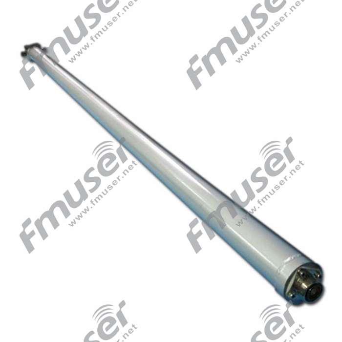
*FMUSER FU-P2 FM ਐਂਟੀਨਾ ਪਾਵਰ ਡਿਵਾਈਡਰ - ਹੋਰ.
ਕਿਵੇਂ ਕਰਦਾ ਹੈ ਐਂਟੀਨਾ ਪਾਵਰ ਡਿਵਾਈਡਰ ਕੰਮ ਕਰਨ?
ਇੱਕ ਐਂਟੀਨਾ ਪਾਵਰ ਡਿਵਾਈਡਰ ਇੱਕ ਅਜਿਹਾ ਉਪਕਰਣ ਹੈ ਜੋ ਇੱਕ ਇਨਪੁਟ ਪੋਰਟ ਤੋਂ ਦੋ ਆਉਟਪੁੱਟ ਪੋਰਟਾਂ ਵਿਚਕਾਰ ਪਾਵਰ (ਬਰਾਬਰ) ਵੰਡਦਾ ਹੈ ਜਾਂ ਦੋ ਐਂਟੀਨਾ ਨੂੰ ਇੱਕ ਐਰੇ ਵਜੋਂ ਜੋੜਦਾ ਹੈ ਅਤੇ ਉਹਨਾਂ ਨੂੰ ਇੱਕ ਟ੍ਰਾਂਸਮੀਟਰ/ਰਿਸੀਵਰ ਸੁਮੇਲ ਜਾਂ ਟ੍ਰਾਂਸਸੀਵਰ ਲਈ 50-ਓਮ ਲੋਡ ਵਜੋਂ ਪੇਸ਼ ਕਰਦਾ ਹੈ। ਆਦਰਸ਼ ਸਥਿਤੀ ਵਿੱਚ, ਇੱਕ ਪਾਵਰ ਡਿਵਾਈਡਰ ਨੂੰ ਨੁਕਸਾਨ ਰਹਿਤ ਮੰਨਿਆ ਜਾ ਸਕਦਾ ਹੈ, ਪਰ ਅਭਿਆਸ ਵਿੱਚ, ਹਮੇਸ਼ਾ ਕੁਝ fmuser-net ਪਾਵਰ ਡਿਸਸੀਪੇਸ਼ਨ ਹੁੰਦਾ ਹੈ। ਡਿਵਾਈਡਰ/ਕੰਬਾਈਨਰ ਟਰਾਂਸਮਿਸ਼ਨ ਲਾਈਨ ਦਾ ਇੱਕ ਚੌਥਾਈ-ਵੇਵ ਸੈਕਸ਼ਨ ਹੋ ਸਕਦਾ ਹੈ ਜਾਂ ਇਹ ਕੈਨ ਅੱਧੀ ਤਰੰਗ ਲੰਬਾਈ ਵਾਲਾ ਭਾਗ ਹੋ ਸਕਦਾ ਹੈ। ਸਿਧਾਂਤਕ ਤੌਰ 'ਤੇ, ਪਾਵਰ ਡਿਵਾਈਡਰ ਅਤੇ ਪਾਵਰ ਕੰਬਾਈਨਰ ਬਿਲਕੁਲ ਇੱਕੋ ਜਿਹੇ ਹਿੱਸੇ ਹੋ ਸਕਦੇ ਹਨ, ਪਰ ਅਭਿਆਸ ਵਿੱਚ, ਕੰਬਾਈਨਰਾਂ ਅਤੇ ਡਿਵਾਈਡਰਾਂ ਲਈ ਵੱਖੋ-ਵੱਖਰੀਆਂ ਲੋੜਾਂ ਹੋ ਸਕਦੀਆਂ ਹਨ, ਜਿਵੇਂ ਕਿ ਪਾਵਰ ਹੈਂਡਲਿੰਗ, ਪੜਾਅ ਮੈਚਿੰਗ, ਪੋਰਟ ਮੈਚ, ਅਤੇ ਆਈਸੋਲੇਸ਼ਨ। ਪਾਵਰ ਡਿਵਾਈਡਰਾਂ ਨੂੰ ਅਕਸਰ ਸਪਲਿਟਰ ਕਿਹਾ ਜਾਂਦਾ ਹੈ। ਹਾਲਾਂਕਿ ਇਹ ਤਕਨੀਕੀ ਤੌਰ 'ਤੇ ਸਹੀ ਹੈ, ਇੰਜੀਨੀਅਰ ਆਮ ਤੌਰ 'ਤੇ "ਸਪਲਿਟਰ" ਸ਼ਬਦ ਨੂੰ ਇੱਕ ਸਸਤੀ ਪ੍ਰਤੀਰੋਧਕ ਬਣਤਰ ਦਾ ਅਰਥ ਰੱਖਣ ਲਈ ਰਿਜ਼ਰਵ ਰੱਖਦੇ ਹਨ ਜੋ ਬਹੁਤ ਚੌੜੀ ਬੈਂਡਵਿਡਥ 'ਤੇ ਪਾਵਰ ਨੂੰ ਵੰਡਦਾ ਹੈ ਪਰ ਕਾਫ਼ੀ ਨੁਕਸਾਨ ਅਤੇ ਸੀਮਤ ਪਾਵਰ ਹੈਂਡਲਿੰਗ ਹੈ।![]()
ਇਸੇ ਐਂਟੀਨਾ ਪਾਵਰ ਡਿਵਾਈਡਰ ਮਹੱਤਵਪੂਰਨ ਹੈ?
ਜਦੋਂ ਤੁਹਾਨੂੰ ਇੱਕ ਮਲਟੀ-ਲੇਅਰ ਐਂਟੀਨਾ ਵਰਤਣ ਦੀ ਲੋੜ ਹੁੰਦੀ ਹੈ ਅਤੇ ਤੁਹਾਡੇ ਟ੍ਰਾਂਸਮੀਟਰ ਵਿੱਚ ਸਿਰਫ਼ ਇੱਕ RF ਇੰਟਰਫੇਸ ਹੁੰਦਾ ਹੈ, ਤਾਂ ਤੁਹਾਨੂੰ ਐਂਟੀਨਾ ਪਾਵਰ ਡਿਵਾਈਡਰ ਦੀ ਵਰਤੋਂ ਕਰਨ ਦੀ ਲੋੜ ਹੁੰਦੀ ਹੈ। ਇਸਦਾ ਕੰਮ ਟ੍ਰਾਂਸਮੀਟਰ ਦੇ ਸਿੰਗਲ ਆਰਐਫ ਇੰਟਰਫੇਸ ਨੂੰ "ਮਲਟੀਪਲ" ਆਰਐਫ ਇੰਟਰਫੇਸ ਵਿੱਚ ਵੰਡਣਾ ਅਤੇ ਇਹਨਾਂ ਇੰਟਰਫੇਸਾਂ ਨੂੰ ਮਲਟੀ-ਲੇਅਰ ਐਂਟੀਨਾ ਨਾਲ ਜੋੜਨਾ ਹੈ। ਉਸੇ ਸਮੇਂ, ਪਾਵਰ ਡਿਵਾਈਡਰ ਟ੍ਰਾਂਸਮੀਟਰ ਦੀ ਆਰਐਫ ਪਾਵਰ ਨੂੰ ਐਂਟੀਨਾ ਦੀ ਹਰੇਕ ਪਰਤ ਵਿੱਚ ਬਰਾਬਰ ਵੰਡ ਦੇਵੇਗਾ, ਰੇ ਕਹਿੰਦਾ ਹੈ।![]()
ਐਂਟੀਨਾ ਟਿਊਨਿੰਗ ਯੂਨਿਟ
ਇੱਕ ਐਂਟੀਨਾ ਟਿਊਨਿੰਗ ਯੂਨਿਟ (ATU) ਇੱਕ ਉਪਕਰਣ ਹੈ ਜੋ ਰੇਡੀਓ ਪ੍ਰਸਾਰਣ ਪ੍ਰਣਾਲੀਆਂ ਵਿੱਚ ਵਰਤਿਆ ਜਾਂਦਾ ਹੈ ਐਂਟੀਨਾ ਸਿਸਟਮ ਦੀ ਕਾਰਗੁਜ਼ਾਰੀ ਨੂੰ ਅਨੁਕੂਲ ਬਣਾਓ. ਇਸਦਾ ਮੁੱਖ ਕੰਮ ਐਂਟੀਨਾ ਦੀ ਰੁਕਾਵਟ ਨੂੰ ਟ੍ਰਾਂਸਮਿਸ਼ਨ ਲਾਈਨ ਦੀ ਰੁਕਾਵਟ ਨਾਲ ਮੇਲਣਾ ਹੈ, ਕੁਸ਼ਲ ਪਾਵਰ ਟ੍ਰਾਂਸਫਰ ਨੂੰ ਯਕੀਨੀ ਬਣਾਉਣਾ ਅਤੇ ਸਿਗਨਲ ਪ੍ਰਤੀਬਿੰਬ ਨੂੰ ਘੱਟ ਕਰਨਾ। ATUs ਵਿਸ਼ੇਸ਼ ਤੌਰ 'ਤੇ ਲਾਭਦਾਇਕ ਹੁੰਦੇ ਹਨ ਜਦੋਂ ਐਂਟੀਨਾ ਅਤੇ ਟਰਾਂਸਮਿਸ਼ਨ ਲਾਈਨ ਦੇ ਵਿਚਕਾਰ ਅੜਿੱਕਾ ਬੇਮੇਲ ਹੁੰਦਾ ਹੈ, ਜੋ ਕਿ ਓਪਰੇਟਿੰਗ ਬਾਰੰਬਾਰਤਾ ਵਿੱਚ ਤਬਦੀਲੀਆਂ ਜਾਂ ਐਂਟੀਨਾ ਦੀਆਂ ਵਿਸ਼ੇਸ਼ਤਾਵਾਂ ਵਿੱਚ ਭਿੰਨਤਾਵਾਂ ਕਾਰਨ ਹੋ ਸਕਦਾ ਹੈ।

* FMUSER ਤੋਂ ਐਂਟੀਨਾ ਟਿਊਨਿੰਗ ਯੂਨਿਟ ਹੱਲ, ਹੋਰ ਜਾਣੋ:
https://www.fmradiobroadcast.com/product/detail/am-antenna-tuning-unit-atu.html
ਐਂਟੀਨਾ ਟਿਊਨਿੰਗ ਯੂਨਿਟ ਕਿਵੇਂ ਕੰਮ ਕਰਦੀ ਹੈ?
ATUs ਪ੍ਰਸਾਰਣ ਲਾਈਨ ਦੇ ਨਾਲ ਇੱਕ ਮੇਲ ਪ੍ਰਾਪਤ ਕਰਨ ਲਈ ਐਂਟੀਨਾ ਸਿਸਟਮ ਦੀਆਂ ਬਿਜਲਈ ਵਿਸ਼ੇਸ਼ਤਾਵਾਂ ਨੂੰ ਵਿਵਸਥਿਤ ਕਰਕੇ ਕੰਮ ਕਰਦੇ ਹਨ, ਖਾਸ ਤੌਰ 'ਤੇ 1:1 ਪ੍ਰਤੀਰੋਧ ਅਨੁਪਾਤ ਲਈ ਟੀਚਾ ਰੱਖਦੇ ਹਨ। ਇਹ ATU ਦੇ ਡਿਜ਼ਾਈਨ 'ਤੇ ਨਿਰਭਰ ਕਰਦੇ ਹੋਏ, ਵੱਖ-ਵੱਖ ਤਰੀਕਿਆਂ ਦੁਆਰਾ ਪ੍ਰਾਪਤ ਕੀਤਾ ਜਾਂਦਾ ਹੈ. ਕੁਝ ATUs ਐਂਟੀਨਾ ਸਿਸਟਮ ਦੀ ਬਿਜਲਈ ਲੰਬਾਈ ਅਤੇ ਰੁਕਾਵਟ ਨੂੰ ਬਦਲਣ ਲਈ ਵੇਰੀਏਬਲ ਕੈਪਸੀਟਰਾਂ ਅਤੇ ਇੰਡਕਟਰਾਂ ਦੀ ਵਰਤੋਂ ਕਰਦੇ ਹਨ। ਇਹਨਾਂ ਕੰਪੋਨੈਂਟਸ ਨੂੰ ਐਡਜਸਟ ਕਰਕੇ, ATU ਅੜਿੱਕੇ ਦੇ ਅੰਤਰਾਂ ਲਈ ਮੁਆਵਜ਼ਾ ਦੇ ਸਕਦਾ ਹੈ ਅਤੇ ਇਹ ਯਕੀਨੀ ਬਣਾ ਸਕਦਾ ਹੈ ਕਿ ਐਂਟੀਨਾ ਸਿਸਟਮ ਟ੍ਰਾਂਸਮਿਸ਼ਨ ਲਾਈਨ ਨਾਲ ਸਹੀ ਤਰ੍ਹਾਂ ਮੇਲ ਖਾਂਦਾ ਹੈ।
ATU ਨੂੰ ਆਮ ਤੌਰ 'ਤੇ ਟ੍ਰਾਂਸਮੀਟਰ ਅਤੇ ਐਂਟੀਨਾ ਦੇ ਵਿਚਕਾਰ ਰੱਖਿਆ ਜਾਂਦਾ ਹੈ, ਅਤੇ ਇਹ ਅਕਸਰ ਐਂਟੀਨਾ ਦੇ ਅਧਾਰ 'ਤੇ ਜਾਂ ਟ੍ਰਾਂਸਮੀਟਰ ਦੇ ਨੇੜੇ ਸਥਿਤ ਹੁੰਦਾ ਹੈ। ਖਾਸ ATU ਡਿਜ਼ਾਈਨ ਅਤੇ ਸਮਰੱਥਾਵਾਂ 'ਤੇ ਨਿਰਭਰ ਕਰਦੇ ਹੋਏ, ਇਸਨੂੰ ਹੱਥੀਂ ਐਡਜਸਟ ਜਾਂ ਆਟੋਮੈਟਿਕਲੀ ਕੰਟਰੋਲ ਕੀਤਾ ਜਾ ਸਕਦਾ ਹੈ।
ਇੱਕ ਐਂਟੀਨਾ ਟਿਊਨਿੰਗ ਯੂਨਿਟ ਚੁਣਨਾ
ਐਂਟੀਨਾ ਟਿਊਨਿੰਗ ਯੂਨਿਟ ਦੀ ਚੋਣ ਕਰਦੇ ਸਮੇਂ ਹੇਠਾਂ ਦਿੱਤੇ ਕਾਰਕਾਂ 'ਤੇ ਗੌਰ ਕਰੋ:
- ਬਾਰੰਬਾਰਤਾ ਸੀਮਾ: ਬਾਰੰਬਾਰਤਾ ਸੀਮਾ ਨਿਰਧਾਰਤ ਕਰੋ ਜਿਸ ਉੱਤੇ ATU ਕੰਮ ਕਰੇਗਾ। ATUs ਨੂੰ ਖਾਸ ਬਾਰੰਬਾਰਤਾ ਰੇਂਜਾਂ ਲਈ ਤਿਆਰ ਕੀਤਾ ਗਿਆ ਹੈ, ਇਸਲਈ ਯਕੀਨੀ ਬਣਾਓ ਕਿ ATU ਤੁਹਾਡੇ ਰੇਡੀਓ ਸਟੇਸ਼ਨ ਦੁਆਰਾ ਵਰਤੇ ਜਾਣ ਵਾਲੇ ਬਾਰੰਬਾਰਤਾ ਬੈਂਡ ਲਈ ਢੁਕਵਾਂ ਹੈ।
- ਪਾਵਰ ਹੈਂਡਲਿੰਗ ਸਮਰੱਥਾ: ATU ਦੀ ਪਾਵਰ ਹੈਂਡਲਿੰਗ ਸਮਰੱਥਾ 'ਤੇ ਗੌਰ ਕਰੋ। ਯਕੀਨੀ ਬਣਾਓ ਕਿ ਇਹ ਤੁਹਾਡੇ ਟ੍ਰਾਂਸਮੀਟਰ ਦੇ ਵੱਧ ਤੋਂ ਵੱਧ ਪਾਵਰ ਆਉਟਪੁੱਟ ਨੂੰ ਨੁਕਸਾਨ ਜਾਂ ਸਿਗਨਲ ਡਿਗਰੇਡੇਸ਼ਨ ਦੇ ਬਿਨਾਂ ਹੈਂਡਲ ਕਰ ਸਕਦਾ ਹੈ।
- ਇੰਪੀਡੈਂਸ ਮੈਚਿੰਗ ਰੇਂਜ: ATU ਦੀ ਪ੍ਰਤੀਰੋਧ ਮੇਲ ਖਾਂਦੀ ਰੇਂਜ ਦੀ ਜਾਂਚ ਕਰੋ। ਇਹ ਤੁਹਾਡੇ ਐਂਟੀਨਾ ਸਿਸਟਮ ਦੇ ਅੜਿੱਕੇ ਨੂੰ ਟਰਾਂਸਮਿਸ਼ਨ ਲਾਈਨ ਦੀ ਰੁਕਾਵਟ ਨਾਲ ਪ੍ਰਭਾਵਸ਼ਾਲੀ ਢੰਗ ਨਾਲ ਮੇਲ ਕਰਨ ਦੇ ਸਮਰੱਥ ਹੋਣਾ ਚਾਹੀਦਾ ਹੈ।
- ਵਿਵਸਥਤਾ: ਵਿਚਾਰ ਕਰੋ ਕਿ ਕੀ ਤੁਹਾਨੂੰ ਮੈਨੂਅਲ ਜਾਂ ਆਟੋਮੈਟਿਕ ATU ਦੀ ਲੋੜ ਹੈ। ਮੈਨੁਅਲ ATUs ਨੂੰ ਮੈਨੂਅਲ ਐਡਜਸਟਮੈਂਟ ਦੀ ਲੋੜ ਹੁੰਦੀ ਹੈ, ਜਦੋਂ ਕਿ ਆਟੋਮੈਟਿਕ ATUs ਸੈਂਸਰਾਂ ਜਾਂ ਕੰਟਰੋਲ ਸਿਸਟਮਾਂ ਤੋਂ ਫੀਡਬੈਕ ਦੇ ਆਧਾਰ 'ਤੇ ਆਪਣੇ ਆਪ ਹੀ ਅੜਿੱਕਾ ਮਿਲਾਨ ਨੂੰ ਅਨੁਕੂਲ ਕਰ ਸਕਦੇ ਹਨ।
- ਇੰਸਟਾਲੇਸ਼ਨ ਅਤੇ ਅਨੁਕੂਲਤਾ: ਯਕੀਨੀ ਬਣਾਓ ਕਿ ATU ਤੁਹਾਡੇ ਐਂਟੀਨਾ ਸਿਸਟਮ ਅਤੇ ਟ੍ਰਾਂਸਮਿਸ਼ਨ ਲਾਈਨ ਦੇ ਅਨੁਕੂਲ ਹੈ। ਸਹੀ ਸਥਾਪਨਾ ਅਤੇ ਏਕੀਕਰਣ ਨੂੰ ਯਕੀਨੀ ਬਣਾਉਣ ਲਈ ਇਨਪੁਟ/ਆਊਟਪੁੱਟ ਕਨੈਕਟਰਾਂ, ਪਾਵਰ ਲੋੜਾਂ ਅਤੇ ਭੌਤਿਕ ਮਾਪਾਂ ਦੀ ਪੁਸ਼ਟੀ ਕਰੋ।
ਆਰਐਫ ਕੈਵਿਟੀ ਫਿਲਟਰ
RF ਕੈਵਿਟੀ ਫਿਲਟਰ ਵਿਸ਼ੇਸ਼ ਫਿਲਟਰ ਹੁੰਦੇ ਹਨ ਜੋ ਰੇਡੀਓ ਫ੍ਰੀਕੁਐਂਸੀ (RF) ਸਿਸਟਮਾਂ ਵਿੱਚ ਵਿਸ਼ੇਸ਼ ਬਾਰੰਬਾਰਤਾ ਬੈਂਡਾਂ ਨੂੰ ਚੋਣਵੇਂ ਤੌਰ 'ਤੇ ਘੱਟ ਕਰਨ ਜਾਂ ਪਾਸ ਕਰਨ ਲਈ ਵਰਤੇ ਜਾਂਦੇ ਹਨ। ਦੇ ਸਿਧਾਂਤ 'ਤੇ ਆਧਾਰਿਤ ਆਰਐਫ ਕੈਵਿਟੀ ਫਿਲਟਰ ਕੰਮ ਕਰਦੇ ਹਨ ਇੱਕ ਗੂੰਜਦੀ ਗੁਫਾ ਦੇ ਅੰਦਰ ਗੂੰਜ. ਉਹਨਾਂ ਵਿੱਚ ਇੱਕ ਜਾਂ ਇੱਕ ਤੋਂ ਵੱਧ ਗੂੰਜਣ ਵਾਲੀਆਂ ਖੱਡਾਂ ਅਤੇ ਜੋੜਨ ਵਾਲੇ ਤੱਤਾਂ ਦੇ ਨਾਲ ਇੱਕ ਧਾਤੂ ਦੀਵਾਰ ਹੁੰਦੀ ਹੈ। ਰੈਜ਼ੋਨੈਂਟ ਕੈਵਿਟੀਜ਼ ਨੂੰ ਖਾਸ ਬਾਰੰਬਾਰਤਾ 'ਤੇ ਗੂੰਜਣ ਲਈ ਟਿਊਨ ਕੀਤਾ ਜਾਂਦਾ ਹੈ, ਜਿਸ ਨਾਲ ਉਹ ਉਹਨਾਂ ਬਾਰੰਬਾਰਤਾ ਰੇਂਜਾਂ ਦੇ ਅੰਦਰ ਸੰਕੇਤਾਂ ਨੂੰ ਘੱਟ ਜਾਂ ਪਾਸ ਕਰ ਸਕਦੇ ਹਨ।

ਜਦੋਂ ਇੱਕ RF ਕੈਵਿਟੀ ਫਿਲਟਰ 'ਤੇ ਇੱਕ ਸਿਗਨਲ ਲਾਗੂ ਕੀਤਾ ਜਾਂਦਾ ਹੈ, ਤਾਂ ਰੈਜ਼ੋਨੈਂਟ ਕੈਵਿਟੀਜ਼ ਉਹਨਾਂ ਦੀ ਗੂੰਜਦੀ ਬਾਰੰਬਾਰਤਾ ਨਾਲ ਮੇਲ ਖਾਂਦੀਆਂ ਬਾਰੰਬਾਰਤਾਵਾਂ ਨੂੰ ਚੋਣਵੇਂ ਤੌਰ 'ਤੇ ਘੱਟ ਜਾਂ ਪਾਸ ਕਰਦੀਆਂ ਹਨ। ਜੋੜਨ ਵਾਲੇ ਤੱਤ ਕੈਵਿਟੀਜ਼ ਦੇ ਵਿਚਕਾਰ ਜੋੜਨ ਦੀ ਮਾਤਰਾ ਨੂੰ ਨਿਯੰਤਰਿਤ ਕਰਦੇ ਹਨ, ਜਿਸ ਨਾਲ ਸਟੀਕ ਬਾਰੰਬਾਰਤਾ ਨਿਯੰਤਰਣ ਅਤੇ ਲੋੜੀਂਦੇ ਫਿਲਟਰ ਵਿਸ਼ੇਸ਼ਤਾਵਾਂ (ਜਿਵੇਂ, ਬੈਂਡਵਿਡਥ, ਸੰਮਿਲਨ ਦਾ ਨੁਕਸਾਨ, ਚੋਣਤਮਕਤਾ) ਦੀ ਆਗਿਆ ਮਿਲਦੀ ਹੈ।
ਆਰਐਫ ਕੈਵਿਟੀ ਫਿਲਟਰ ਚੁਣਨਾ
RF ਕੈਵਿਟੀ ਫਿਲਟਰਾਂ ਦੀ ਚੋਣ ਕਰਦੇ ਸਮੇਂ ਹੇਠਾਂ ਦਿੱਤੇ ਕਾਰਕਾਂ 'ਤੇ ਗੌਰ ਕਰੋ:
- ਬਾਰੰਬਾਰਤਾ ਸੀਮਾ: ਤੁਹਾਨੂੰ ਫਿਲਟਰ ਕਰਨ ਲਈ ਲੋੜੀਂਦੀ ਬਾਰੰਬਾਰਤਾ ਰੇਂਜ ਦਾ ਪਤਾ ਲਗਾਓ। ਇੱਕ RF ਕੈਵਿਟੀ ਫਿਲਟਰ ਚੁਣੋ ਜੋ ਤੁਹਾਡੀ ਐਪਲੀਕੇਸ਼ਨ ਦੀ ਖਾਸ ਬਾਰੰਬਾਰਤਾ ਸੀਮਾ ਨੂੰ ਕਵਰ ਕਰਦਾ ਹੈ।
- ਫਿਲਟਰ ਵਿਸ਼ੇਸ਼ਤਾਵਾਂ: ਵੱਖ-ਵੱਖ ਕੈਵਿਟੀ ਫਿਲਟਰਾਂ ਵਿੱਚ ਵੱਖ-ਵੱਖ ਵਿਸ਼ੇਸ਼ਤਾਵਾਂ ਹੁੰਦੀਆਂ ਹਨ ਜਿਵੇਂ ਕਿ ਬੈਂਡਵਿਡਥ, ਸੰਮਿਲਨ ਦਾ ਨੁਕਸਾਨ, ਚੋਣ, ਅਤੇ ਅਸਵੀਕਾਰ ਕਰਨਾ। ਆਪਣੇ RF ਸਿਸਟਮ ਦੀਆਂ ਖਾਸ ਲੋੜਾਂ 'ਤੇ ਵਿਚਾਰ ਕਰੋ ਅਤੇ ਉਹਨਾਂ ਲੋੜਾਂ ਨੂੰ ਪੂਰਾ ਕਰਨ ਵਾਲਾ ਫਿਲਟਰ ਚੁਣੋ।
- ਪਾਵਰ ਹੈਂਡਲਿੰਗ ਸਮਰੱਥਾ: ਪੁਸ਼ਟੀ ਕਰੋ ਕਿ RF ਕੈਵਿਟੀ ਫਿਲਟਰ ਤੁਹਾਡੀ ਐਪਲੀਕੇਸ਼ਨ ਦੇ ਪਾਵਰ ਪੱਧਰਾਂ ਨੂੰ ਸੰਭਾਲ ਸਕਦਾ ਹੈ। ਇਹ ਸੁਨਿਸ਼ਚਿਤ ਕਰੋ ਕਿ ਇਹ ਬਿਨਾਂ ਕਿਸੇ ਵਿਗਾੜ ਜਾਂ ਨੁਕਸਾਨ ਦੇ ਸ਼ਕਤੀ ਦਾ ਸਾਮ੍ਹਣਾ ਕਰ ਸਕਦਾ ਹੈ।
- ਫਿਲਟਰ ਟੋਪੋਲੋਜੀ: ਫਿਲਟਰ ਟੋਪੋਲੋਜੀ 'ਤੇ ਵਿਚਾਰ ਕਰੋ ਜੋ ਤੁਹਾਡੀ ਐਪਲੀਕੇਸ਼ਨ ਦੇ ਅਨੁਕੂਲ ਹੈ। ਵੱਖ-ਵੱਖ ਕੈਵਿਟੀ ਫਿਲਟਰ ਡਿਜ਼ਾਈਨ, ਜਿਵੇਂ ਕਿ ਕੰਬਲਾਈਨ ਫਿਲਟਰ, ਇੰਟਰਡਿਜੀਟਲ ਫਿਲਟਰ, ਅਤੇ ਆਇਰਿਸ-ਕਪਲਡ ਫਿਲਟਰ, ਦੀਆਂ ਵੱਖੋ ਵੱਖਰੀਆਂ ਵਿਸ਼ੇਸ਼ਤਾਵਾਂ ਅਤੇ ਪ੍ਰਦਰਸ਼ਨ ਹਨ।
- ਵਾਤਾਵਰਣ ਸੰਬੰਧੀ ਵਿਚਾਰ: ਵਾਤਾਵਰਣ ਦੀਆਂ ਸਥਿਤੀਆਂ ਦਾ ਮੁਲਾਂਕਣ ਕਰੋ ਜਿਸ ਨਾਲ RF ਕੈਵਿਟੀ ਫਿਲਟਰ ਦਾ ਸਾਹਮਣਾ ਕੀਤਾ ਜਾਵੇਗਾ, ਜਿਵੇਂ ਕਿ ਤਾਪਮਾਨ, ਨਮੀ, ਅਤੇ ਵਾਈਬ੍ਰੇਸ਼ਨ। ਯਕੀਨੀ ਬਣਾਓ ਕਿ ਚੁਣਿਆ ਗਿਆ ਫਿਲਟਰ ਤੁਹਾਡੀ ਐਪਲੀਕੇਸ਼ਨ ਦੀਆਂ ਖਾਸ ਵਾਤਾਵਰਨ ਲੋੜਾਂ ਲਈ ਢੁਕਵਾਂ ਹੈ।
- ਆਕਾਰ ਅਤੇ ਫਾਰਮ ਫੈਕਟਰ: ਫਿਲਟਰ ਦੇ ਭੌਤਿਕ ਆਕਾਰ ਅਤੇ ਫਾਰਮ ਫੈਕਟਰ 'ਤੇ ਗੌਰ ਕਰੋ। ਯਕੀਨੀ ਬਣਾਓ ਕਿ ਇਹ ਉਪਲਬਧ ਥਾਂ ਦੇ ਅੰਦਰ ਫਿੱਟ ਹੈ ਅਤੇ ਤੁਹਾਡੇ RF ਸਿਸਟਮ ਵਿੱਚ ਆਸਾਨੀ ਨਾਲ ਏਕੀਕ੍ਰਿਤ ਕੀਤਾ ਜਾ ਸਕਦਾ ਹੈ।
FM ਕੈਵਿਟੀ ਫਿਲਟਰ
ਇੱਕ FM ਕੈਵਿਟੀ ਫਿਲਟਰ ਖਾਸ ਤੌਰ 'ਤੇ FM (ਫ੍ਰੀਕੁਐਂਸੀ ਮੋਡੂਲੇਸ਼ਨ) ਸਿਗਨਲਾਂ ਨੂੰ ਫਿਲਟਰ ਕਰਨ ਲਈ ਤਿਆਰ ਕੀਤਾ ਗਿਆ ਹੈ। ਇਹ FM ਰੇਡੀਓ ਸਿਸਟਮਾਂ ਵਿੱਚ ਸਹੀ ਸਿਗਨਲ ਟ੍ਰਾਂਸਮਿਸ਼ਨ ਅਤੇ ਰਿਸੈਪਸ਼ਨ ਨੂੰ ਯਕੀਨੀ ਬਣਾਉਣ ਲਈ ਲੋੜੀਂਦੇ ਬਾਰੰਬਾਰਤਾ ਬੈਂਡ ਨੂੰ ਘੱਟ ਕਰਨ ਜਾਂ ਪਾਸ ਕਰਨ ਵਿੱਚ ਮਦਦ ਕਰਦਾ ਹੈ। FM ਕੈਵਿਟੀ ਫਿਲਟਰ ਆਮ ਤੌਰ 'ਤੇ ਪ੍ਰਸਾਰਣ ਪ੍ਰਣਾਲੀਆਂ, ਰੇਡੀਓ ਟ੍ਰਾਂਸਮੀਟਰਾਂ, ਅਤੇ FM ਬਾਰੰਬਾਰਤਾ ਰੇਂਜ ਵਿੱਚ ਕੰਮ ਕਰਨ ਵਾਲੇ ਰਿਸੀਵਰਾਂ ਵਿੱਚ ਵਰਤੇ ਜਾਂਦੇ ਹਨ।
ਤੁਹਾਡੇ ਲਈ ਸਿਫ਼ਾਰਿਸ਼ ਕੀਤੇ FM ਫਿਲਟਰ
 |
 |
 |
| 500W ਬੈਂਡਪਾਸ | 1500W ਬੈਂਡਪਾਸ | 3000W ਬੈਂਡਪਾਸ |
 |
 |
 |
| 5000W ਬੈਂਡਪਾਸ |
100kW ਬੈਂਡਪਾਸ |
200kW ਬੈਂਡਪਾਸ |
ਵੀਐਚਐਫ ਗੁਣਾ ਫਿਲਟਰ
VHF (ਬਹੁਤ ਉੱਚ ਫ੍ਰੀਕੁਐਂਸੀ) ਕੈਵਿਟੀ ਫਿਲਟਰ VHF ਬਾਰੰਬਾਰਤਾ ਬੈਂਡ ਵਿੱਚ ਸਿਗਨਲਾਂ ਨੂੰ ਫਿਲਟਰ ਕਰਨ ਲਈ ਤਿਆਰ ਕੀਤਾ ਗਿਆ ਹੈ, ਖਾਸ ਤੌਰ 'ਤੇ 30 MHz ਤੋਂ 300 MHz ਤੱਕ। ਇਹ ਆਮ ਤੌਰ 'ਤੇ ਟੈਲੀਵਿਜ਼ਨ ਪ੍ਰਸਾਰਣ, ਵਾਇਰਲੈੱਸ ਸੰਚਾਰ ਪ੍ਰਣਾਲੀਆਂ, ਅਤੇ VHF ਬਾਰੰਬਾਰਤਾ ਰੇਂਜ ਵਿੱਚ ਕੰਮ ਕਰਨ ਵਾਲੇ ਜਨਤਕ ਸੁਰੱਖਿਆ ਰੇਡੀਓ ਸਮੇਤ ਵੱਖ-ਵੱਖ ਐਪਲੀਕੇਸ਼ਨਾਂ ਵਿੱਚ ਵਰਤੇ ਜਾਂਦੇ ਹਨ।
ਤੁਹਾਡੇ ਲਈ ਸਿਫ਼ਾਰਿਸ਼ ਕੀਤੇ VHF ਫਿਲਟਰ
 |
 |
 |
 |
| 500W ਬੈਂਡਪਾਸ | 1500W ਬੈਂਡਪਾਸ | 3000W ਬੈਂਡਪਾਸ | 5000W ਬੈਂਡਪਾਸ |
 |
 |
 |
| 10000W ਬੈਂਡਪਾਸ | 10000W ਬੈਂਡਪਾਸ | 10000W ਬੈਂਡਪਾਸ |
UHF ਕੈਵਿਟੀ ਫਿਲਟਰ
UHF (ਅਲਟਰਾ ਹਾਈ ਫ੍ਰੀਕੁਐਂਸੀ) ਕੈਵਿਟੀ ਫਿਲਟਰ UHF ਬਾਰੰਬਾਰਤਾ ਬੈਂਡ ਲਈ ਤਿਆਰ ਕੀਤੇ ਗਏ ਹਨ, ਜੋ ਆਮ ਤੌਰ 'ਤੇ 300 MHz ਤੋਂ 3 GHz ਤੱਕ ਹੁੰਦੇ ਹਨ। ਉਹ ਵਿਆਪਕ ਤੌਰ 'ਤੇ ਟੈਲੀਵਿਜ਼ਨ ਪ੍ਰਸਾਰਣ, ਵਾਇਰਲੈੱਸ ਸੰਚਾਰ ਪ੍ਰਣਾਲੀਆਂ, ਰਾਡਾਰ ਪ੍ਰਣਾਲੀਆਂ, ਅਤੇ UHF ਬਾਰੰਬਾਰਤਾ ਰੇਂਜ ਵਿੱਚ ਕੰਮ ਕਰਨ ਵਾਲੀਆਂ ਹੋਰ ਆਰਐਫ ਐਪਲੀਕੇਸ਼ਨਾਂ ਵਿੱਚ ਵਰਤੇ ਜਾਂਦੇ ਹਨ।
ਤੁਹਾਡੇ ਲਈ ਸਿਫ਼ਾਰਿਸ਼ ਕੀਤੇ UHF ਫਿਲਟਰ
 |
 |
 |
| 350W DTV ਬੈਂਡਪਾਸ | 750W DTV ਬੈਂਡਪਾਸ | 1600W DTV ਬੈਂਡਪਾਸ |
 |
 |
 |
| 3000W DTV ਬੈਂਡਪਾਸ |
5500W DTV ਬੈਂਡਪਾਸ |
20kW ਬੈਂਡਪਾਸ |
ਐਲ ਬੈਂਡ ਕੈਵਿਟੀ ਫਿਲਟਰ
An ਐਲ ਬੈਂਡ ਕੈਵਿਟੀ ਫਿਲਟਰ L ਬੈਂਡ ਫ੍ਰੀਕੁਐਂਸੀ ਰੇਂਜ ਵਿੱਚ ਕੰਮ ਕਰਨ ਲਈ ਤਿਆਰ ਕੀਤਾ ਗਿਆ ਹੈ, ਖਾਸ ਤੌਰ 'ਤੇ 1 GHz ਤੋਂ 2 GHz ਤੱਕ। ਐਲ ਬੈਂਡ ਦੀ ਵਰਤੋਂ ਆਮ ਤੌਰ 'ਤੇ ਸੈਟੇਲਾਈਟ ਸੰਚਾਰ, ਏਅਰੋਨਾਟਿਕਲ ਐਪਲੀਕੇਸ਼ਨਾਂ, ਅਤੇ ਵਾਇਰਲੈੱਸ ਪ੍ਰਣਾਲੀਆਂ ਵਿੱਚ ਕੀਤੀ ਜਾਂਦੀ ਹੈ ਜਿਨ੍ਹਾਂ ਨੂੰ ਲੰਬੀ ਦੂਰੀ ਦੇ ਸੰਚਾਰ ਦੀ ਲੋੜ ਹੁੰਦੀ ਹੈ।
ਤੁਹਾਡੇ ਲਈ ਸਿਫ਼ਾਰਿਸ਼ ਕੀਤੇ FM ਟ੍ਰਾਂਸਮੀਟਰ
 |
| 3kW ਬੈਂਡਪਾਸ |
ਆਰਐਫ ਹਾਈਬ੍ਰਿਡ ਕਪਲਰਸ
ਆਰਐਫ ਹਾਈਬ੍ਰਿਡ ਕਪਲਰਸ ਪੈਸਿਵ ਡਿਵਾਈਸ ਹਨ ਜੋ ਆਰਐਫ ਸਿਸਟਮਾਂ ਵਿੱਚ ਵਰਤੇ ਜਾਂਦੇ ਹਨ ਸੰਕੇਤਾਂ ਨੂੰ ਜੋੜਨਾ ਜਾਂ ਵੰਡਣਾ ਇਨਪੁਟ ਅਤੇ ਆਉਟਪੁੱਟ ਪੋਰਟਾਂ ਵਿਚਕਾਰ ਅਲੱਗ-ਥਲੱਗਤਾ ਨੂੰ ਕਾਇਮ ਰੱਖਦੇ ਹੋਏ।

RF ਹਾਈਬ੍ਰਿਡ ਕਪਲਰ ਕਿਵੇਂ ਕੰਮ ਕਰਦੇ ਹਨ
ਆਰਐਫ ਹਾਈਬ੍ਰਿਡ ਕਪਲਰ ਪਾਵਰ ਡਿਵੀਜ਼ਨ ਦੇ ਸਿਧਾਂਤ 'ਤੇ ਅਧਾਰਤ ਕੰਮ ਕਰਦੇ ਹਨ ਅਤੇ ਚਾਰ-ਪੋਰਟ ਨੈਟਵਰਕ ਦੇ ਅੰਦਰ ਜੋੜਦੇ ਹਨ। ਇਹਨਾਂ ਵਿੱਚ ਦੋ ਇੰਪੁੱਟ ਪੋਰਟਾਂ (ਅਕਸਰ ਮੁੱਖ ਅਤੇ ਜੋੜੀ ਪੋਰਟਾਂ ਵਜੋਂ ਜਾਣੀਆਂ ਜਾਂਦੀਆਂ ਹਨ) ਅਤੇ ਦੋ ਆਉਟਪੁੱਟ ਪੋਰਟਾਂ ਹੁੰਦੀਆਂ ਹਨ। ਮੁੱਖ ਪੋਰਟ ਮੁੱਖ ਸਿਗਨਲ ਸਰੋਤ ਨਾਲ ਜੁੜਿਆ ਹੋਇਆ ਹੈ, ਜਦੋਂ ਕਿ ਜੋੜੀ ਪੋਰਟ ਕਪਲਡ ਸਿਗਨਲ ਨਾਲ ਜੁੜਦੀ ਹੈ। ਬਾਕੀ ਦੋ ਪੋਰਟ ਆਉਟਪੁੱਟ ਪੋਰਟ ਹਨ।
RF ਹਾਈਬ੍ਰਿਡ ਕਪਲਰ ਮੁੱਖ ਪੋਰਟ ਤੋਂ ਪਾਵਰ ਨੂੰ ਦੋ ਮਾਰਗਾਂ ਵਿੱਚ ਵੰਡ ਕੇ ਕੰਮ ਕਰਦਾ ਹੈ: ਇੱਕ ਜੋ ਸਿੱਧਾ ਇੱਕ ਆਉਟਪੁੱਟ ਪੋਰਟ ਤੇ ਜਾਂਦਾ ਹੈ ਅਤੇ ਦੂਜਾ ਜੋ ਦੂਜੇ ਆਉਟਪੁੱਟ ਪੋਰਟ ਨਾਲ ਜੋੜਿਆ ਜਾਂਦਾ ਹੈ। ਇਹ ਇੰਪੁੱਟ ਅਤੇ ਆਉਟਪੁੱਟ ਪੋਰਟਾਂ ਵਿਚਕਾਰ ਉੱਚ ਆਈਸੋਲੇਸ਼ਨ ਨੂੰ ਕਾਇਮ ਰੱਖਦੇ ਹੋਏ ਪਾਵਰ ਡਿਵੀਜ਼ਨ ਅਤੇ ਸਿਗਨਲ ਕਪਲਿੰਗ ਦੀ ਆਗਿਆ ਦਿੰਦਾ ਹੈ।
ਪਾਵਰ ਸਪਲਿਟ ਅਤੇ ਕਪਲਿੰਗ ਦੀ ਮਾਤਰਾ ਹਾਈਬ੍ਰਿਡ ਕਪਲਰ ਦੇ ਡਿਜ਼ਾਈਨ ਅਤੇ ਵਿਸ਼ੇਸ਼ਤਾਵਾਂ ਦੁਆਰਾ ਨਿਰਧਾਰਤ ਕੀਤੀ ਜਾਂਦੀ ਹੈ, ਜਿਵੇਂ ਕਿ ਕਪਲਿੰਗ ਅਨੁਪਾਤ ਅਤੇ ਅਲੱਗ-ਥਲੱਗ। ਕਪਲਿੰਗ ਅਨੁਪਾਤ ਆਉਟਪੁੱਟ ਪੋਰਟਾਂ ਦੇ ਵਿਚਕਾਰ ਪਾਵਰ ਦੀ ਵੰਡ ਨੂੰ ਨਿਰਧਾਰਤ ਕਰਦਾ ਹੈ, ਜਦੋਂ ਕਿ ਅਲੱਗ-ਥਲੱਗ ਇਨਪੁਟ ਅਤੇ ਆਉਟਪੁੱਟ ਪੋਰਟਾਂ ਵਿਚਕਾਰ ਘੱਟੋ-ਘੱਟ ਸਿਗਨਲ ਲੀਕੇਜ ਨੂੰ ਯਕੀਨੀ ਬਣਾਉਂਦਾ ਹੈ।
RF ਹਾਈਬ੍ਰਿਡ ਕਪਲਰ ਚੁਣਨਾ
ਆਰਐਫ ਹਾਈਬ੍ਰਿਡ ਕਪਲਰਾਂ ਦੀ ਚੋਣ ਕਰਦੇ ਸਮੇਂ ਹੇਠਾਂ ਦਿੱਤੇ ਕਾਰਕਾਂ 'ਤੇ ਗੌਰ ਕਰੋ:
- ਬਾਰੰਬਾਰਤਾ ਸੀਮਾ: ਉਸ ਬਾਰੰਬਾਰਤਾ ਸੀਮਾ ਨੂੰ ਨਿਰਧਾਰਤ ਕਰੋ ਜਿਸ ਨਾਲ ਤੁਹਾਨੂੰ ਕੰਮ ਕਰਨ ਦੀ ਲੋੜ ਹੈ। ਇੱਕ RF ਹਾਈਬ੍ਰਿਡ ਕਪਲਰ ਚੁਣੋ ਜੋ ਤੁਹਾਡੀ ਐਪਲੀਕੇਸ਼ਨ ਦੀ ਖਾਸ ਬਾਰੰਬਾਰਤਾ ਸੀਮਾ ਨੂੰ ਕਵਰ ਕਰਦਾ ਹੈ।
- ਜੋੜ ਅਨੁਪਾਤ: ਤੁਹਾਡੇ ਸਿਸਟਮ ਲਈ ਲੋੜੀਂਦੇ ਕਪਲਿੰਗ ਅਨੁਪਾਤ ਦਾ ਮੁਲਾਂਕਣ ਕਰੋ। ਕਪਲਿੰਗ ਅਨੁਪਾਤ ਆਉਟਪੁੱਟ ਪੋਰਟਾਂ ਵਿਚਕਾਰ ਪਾਵਰ ਦੀ ਵੰਡ ਨੂੰ ਨਿਰਧਾਰਤ ਕਰਦਾ ਹੈ। ਆਪਣੇ ਸਿਸਟਮ ਦੀਆਂ ਲੋੜਾਂ ਦੇ ਆਧਾਰ 'ਤੇ ਉਚਿਤ ਕਪਲਿੰਗ ਅਨੁਪਾਤ ਵਾਲਾ ਹਾਈਬ੍ਰਿਡ ਕਪਲਰ ਚੁਣੋ।
- ਇਨਸੂਲੇਸ਼ਨ: ਪੋਰਟਾਂ ਵਿਚਕਾਰ ਅਲੱਗ-ਥਲੱਗ ਦੇ ਲੋੜੀਂਦੇ ਪੱਧਰ 'ਤੇ ਵਿਚਾਰ ਕਰੋ। ਉੱਚ ਆਈਸੋਲੇਸ਼ਨ ਇਨਪੁਟ ਅਤੇ ਆਉਟਪੁੱਟ ਪੋਰਟਾਂ ਵਿਚਕਾਰ ਘੱਟੋ-ਘੱਟ ਸਿਗਨਲ ਲੀਕੇਜ ਨੂੰ ਯਕੀਨੀ ਬਣਾਉਂਦਾ ਹੈ। ਆਪਣੀ ਐਪਲੀਕੇਸ਼ਨ ਲਈ ਕਾਫੀ ਅਲੱਗ-ਥਲੱਗ ਵਾਲਾ ਇੱਕ ਹਾਈਬ੍ਰਿਡ ਕਪਲਰ ਚੁਣੋ।
- ਪਾਵਰ ਹੈਂਡਲਿੰਗ ਸਮਰੱਥਾ: ਪੁਸ਼ਟੀ ਕਰੋ ਕਿ RF ਹਾਈਬ੍ਰਿਡ ਕਪਲਰ ਤੁਹਾਡੀ ਐਪਲੀਕੇਸ਼ਨ ਦੇ ਪਾਵਰ ਪੱਧਰਾਂ ਨੂੰ ਸੰਭਾਲ ਸਕਦਾ ਹੈ। ਇਹ ਸੁਨਿਸ਼ਚਿਤ ਕਰੋ ਕਿ ਇਹ ਬਿਨਾਂ ਕਿਸੇ ਵਿਗਾੜ ਜਾਂ ਨੁਕਸਾਨ ਦੇ ਸ਼ਕਤੀ ਦਾ ਸਾਮ੍ਹਣਾ ਕਰ ਸਕਦਾ ਹੈ।
- ਵਾਤਾਵਰਣ ਸੰਬੰਧੀ ਵਿਚਾਰ: ਵਾਤਾਵਰਣ ਦੀਆਂ ਸਥਿਤੀਆਂ ਦਾ ਮੁਲਾਂਕਣ ਕਰੋ ਜਿਸ ਨਾਲ ਹਾਈਬ੍ਰਿਡ ਕਪਲਰ ਦਾ ਸਾਹਮਣਾ ਕੀਤਾ ਜਾਵੇਗਾ, ਜਿਵੇਂ ਕਿ ਤਾਪਮਾਨ, ਨਮੀ ਅਤੇ ਵਾਈਬ੍ਰੇਸ਼ਨ। ਇਹ ਸੁਨਿਸ਼ਚਿਤ ਕਰੋ ਕਿ ਚੁਣਿਆ ਗਿਆ ਕਪਲਰ ਤੁਹਾਡੀ ਐਪਲੀਕੇਸ਼ਨ ਦੀਆਂ ਖਾਸ ਵਾਤਾਵਰਣ ਸੰਬੰਧੀ ਜ਼ਰੂਰਤਾਂ ਲਈ ਢੁਕਵਾਂ ਹੈ।
- ਆਕਾਰ ਅਤੇ ਫਾਰਮ ਫੈਕਟਰ: ਹਾਈਬ੍ਰਿਡ ਕਪਲਰ ਦੇ ਭੌਤਿਕ ਆਕਾਰ ਅਤੇ ਫਾਰਮ ਫੈਕਟਰ 'ਤੇ ਗੌਰ ਕਰੋ। ਯਕੀਨੀ ਬਣਾਓ ਕਿ ਇਹ ਉਪਲਬਧ ਥਾਂ ਦੇ ਅੰਦਰ ਫਿੱਟ ਹੈ ਅਤੇ ਤੁਹਾਡੇ RF ਸਿਸਟਮ ਵਿੱਚ ਆਸਾਨੀ ਨਾਲ ਏਕੀਕ੍ਰਿਤ ਕੀਤਾ ਜਾ ਸਕਦਾ ਹੈ।
VHF ਕਪਲਰਸ
VHF (ਬਹੁਤ ਉੱਚ ਫ੍ਰੀਕੁਐਂਸੀ) ਕਪਲਰ VHF ਬਾਰੰਬਾਰਤਾ ਸੀਮਾ ਵਿੱਚ ਕੰਮ ਕਰਨ ਲਈ ਤਿਆਰ ਕੀਤੇ ਗਏ ਹਨ, ਖਾਸ ਤੌਰ 'ਤੇ 30 MHz ਤੋਂ 300 MHz ਤੱਕ। ਉਹ ਬੰਦਰਗਾਹਾਂ ਦੇ ਵਿਚਕਾਰ ਉੱਚ ਆਈਸੋਲੇਸ਼ਨ ਨੂੰ ਕਾਇਮ ਰੱਖਦੇ ਹੋਏ VHF ਸਿਗਨਲਾਂ ਨੂੰ ਜੋੜਨ ਜਾਂ ਵੰਡਣ ਲਈ ਵਰਤੇ ਜਾਂਦੇ ਹਨ। VHF ਕਪਲਰਸ ਆਮ ਤੌਰ 'ਤੇ ਐਪਲੀਕੇਸ਼ਨਾਂ ਜਿਵੇਂ ਕਿ ਟੈਲੀਵਿਜ਼ਨ ਪ੍ਰਸਾਰਣ, ਵਾਇਰਲੈੱਸ ਸੰਚਾਰ ਪ੍ਰਣਾਲੀਆਂ, ਅਤੇ VHF ਬਾਰੰਬਾਰਤਾ ਰੇਂਜ ਵਿੱਚ ਕੰਮ ਕਰਨ ਵਾਲੇ RF ਐਂਪਲੀਫਾਇਰ ਵਿੱਚ ਵਰਤੇ ਜਾਂਦੇ ਹਨ।
ਤੁਹਾਡੇ ਲਈ ਸਿਫ਼ਾਰਿਸ਼ ਕੀਤੇ VHF ਕਪਲਰ


UHF ਕਪਲਰਸ
UHF (ਅਲਟਰਾ ਹਾਈ ਫ੍ਰੀਕੁਐਂਸੀ) ਕਪਲਰ UHF ਬਾਰੰਬਾਰਤਾ ਬੈਂਡ ਲਈ ਤਿਆਰ ਕੀਤੇ ਗਏ ਹਨ, ਜੋ ਆਮ ਤੌਰ 'ਤੇ 300 MHz ਤੋਂ 3 GHz ਤੱਕ ਫੈਲਦਾ ਹੈ। UHF ਕਪਲਰ ਪੋਰਟਾਂ ਵਿਚਕਾਰ ਅਲੱਗ-ਥਲੱਗਤਾ ਨੂੰ ਕਾਇਮ ਰੱਖਦੇ ਹੋਏ UHF ਸਿਗਨਲਾਂ ਨੂੰ ਜੋੜਨ ਜਾਂ ਵੰਡਣ ਨੂੰ ਸਮਰੱਥ ਬਣਾਉਂਦੇ ਹਨ। ਉਹ ਟੈਲੀਵਿਜ਼ਨ ਪ੍ਰਸਾਰਣ, ਵਾਇਰਲੈੱਸ ਸੰਚਾਰ ਪ੍ਰਣਾਲੀਆਂ, ਰਾਡਾਰ ਪ੍ਰਣਾਲੀਆਂ, ਅਤੇ UHF ਫ੍ਰੀਕੁਐਂਸੀ ਰੇਂਜ ਵਿੱਚ ਕੰਮ ਕਰਨ ਵਾਲੇ ਹੋਰ ਆਰਐਫ ਸਿਸਟਮਾਂ ਵਿੱਚ ਐਪਲੀਕੇਸ਼ਨ ਲੱਭਦੇ ਹਨ।
ਤੁਹਾਡੇ ਲਈ ਸਿਫ਼ਾਰਿਸ਼ ਕੀਤੇ UHF ਕਪਲਰ
 |
 |
 |
| 1-5/8” 5kW 3dB ਹਾਈਬ੍ਰਿਡ UHF | 1-5/8" 8kW 3dB 4 ਪੋਰਟਸ ਹਾਈਬ੍ਰਿਡ FM | 1-5/8" 15kW 3dB ਹਾਈਬ੍ਰਿਡ UHF |
 |
 |
 |
| 1-5/8" 20kW 3dB ਹਾਈਬ੍ਰਿਡ UHF |
3-1/8" 25kW 3dB ਹਾਈਬ੍ਰਿਡ UHF |
4-1/2" 40kW 3dB ਹਾਈਬ੍ਰਿਡ UHF |
ਐਲ ਬੈਂਡ ਕਪਲਰ
ਐਲ ਬੈਂਡ ਕਪਲਰਸ ਖਾਸ ਤੌਰ 'ਤੇ L ਬੈਂਡ ਫ੍ਰੀਕੁਐਂਸੀ ਰੇਂਜ ਲਈ ਤਿਆਰ ਕੀਤੇ ਗਏ ਹਨ, ਖਾਸ ਤੌਰ 'ਤੇ 1 GHz ਤੋਂ 2 GHz ਤੱਕ। ਇਹਨਾਂ ਦੀ ਵਰਤੋਂ ਬੰਦਰਗਾਹਾਂ ਵਿਚਕਾਰ ਅਲੱਗ-ਥਲੱਗਤਾ ਨੂੰ ਕਾਇਮ ਰੱਖਦੇ ਹੋਏ ਐਲ ਬੈਂਡ ਸਿਗਨਲਾਂ ਨੂੰ ਜੋੜਨ ਜਾਂ ਵੰਡਣ ਲਈ ਕੀਤੀ ਜਾਂਦੀ ਹੈ। L ਬੈਂਡ ਕਪਲਰਸ ਆਮ ਤੌਰ 'ਤੇ ਸੈਟੇਲਾਈਟ ਸੰਚਾਰ ਪ੍ਰਣਾਲੀਆਂ, ਏਅਰੋਨਾਟਿਕਲ ਐਪਲੀਕੇਸ਼ਨਾਂ, ਅਤੇ ਵਾਇਰਲੈੱਸ ਪ੍ਰਣਾਲੀਆਂ ਵਿੱਚ ਵਰਤੇ ਜਾਂਦੇ ਹਨ ਜਿਨ੍ਹਾਂ ਨੂੰ ਲੰਬੀ ਦੂਰੀ ਦੇ ਸੰਚਾਰ ਦੀ ਲੋੜ ਹੁੰਦੀ ਹੈ।
ਤੁਹਾਡੇ ਲਈ ਸਿਫ਼ਾਰਸ਼ੀ ਐਲ-ਬੈਂਡ ਕਪਲਰ
 |
 |
| 1-5/8" 4kW 3dB ਹਾਈਬ੍ਰਿਡ L-ਬੈਂਡ | 1-5/8", 7/16 ਦਿਨ, 3 ਪੋਰਟਸ 4kW 3dB ਹਾਈਬ੍ਰਿਡ L-ਬੈਂਡ |
ਟ੍ਰਾਂਸਮੀਟਰ ਕੰਬਾਈਨਰ
ਟ੍ਰਾਂਸਮੀਟਰ ਕੰਬਾਈਨਰ ਇੱਕ ਸਿੰਗਲ ਟਰਾਂਸਮਿਸ਼ਨ ਲਾਈਨ ਵਿੱਚ ਮਲਟੀਪਲ ਟ੍ਰਾਂਸਮੀਟਰਾਂ ਦੇ ਆਉਟਪੁੱਟ ਸਿਗਨਲਾਂ ਨੂੰ ਜੋੜਨ ਲਈ RF ਸਿਸਟਮਾਂ ਵਿੱਚ ਵਰਤੇ ਜਾਂਦੇ ਉਪਕਰਣ ਹਨ।

ਟ੍ਰਾਂਸਮੀਟਰ ਕੰਬਾਈਨਰ ਕਿਵੇਂ ਕੰਮ ਕਰਦੇ ਹਨ
ਟਰਾਂਸਮੀਟਰ ਕੰਬਾਈਨਰ ਬਹੁਤ ਸਾਰੇ ਟਰਾਂਸਮੀਟਰਾਂ ਦੇ ਆਉਟਪੁੱਟ ਸਿਗਨਲਾਂ ਨੂੰ ਇੱਕ ਆਮ ਪ੍ਰਸਾਰਣ ਲਾਈਨ ਵਿੱਚ ਜੋੜ ਕੇ ਕੰਮ ਕਰਦੇ ਹਨ ਜਦੋਂ ਕਿ ਉਚਿਤ ਰੁਕਾਵਟ ਮੇਲ ਅਤੇ ਅਲੱਗਤਾ ਨੂੰ ਕਾਇਮ ਰੱਖਦੇ ਹੋਏ। ਉਹਨਾਂ ਵਿੱਚ ਆਮ ਤੌਰ 'ਤੇ ਫਿਲਟਰ, ਡਿਵਾਈਡਰ ਅਤੇ ਕੰਬਾਈਨਰ ਨੈੱਟਵਰਕ ਹੁੰਦੇ ਹਨ।
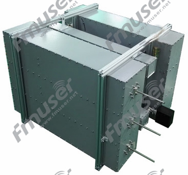
ਇੱਕ ਟ੍ਰਾਂਸਮੀਟਰ ਕੰਬਾਈਨਰ ਵਿੱਚ ਫਿਲਟਰਾਂ ਦੀ ਵਰਤੋਂ ਵਿਅਕਤੀਗਤ ਟ੍ਰਾਂਸਮੀਟਰ ਆਉਟਪੁੱਟ ਨੂੰ ਅਲੱਗ ਕਰਨ ਅਤੇ ਅਣਚਾਹੇ ਇੰਟਰਮੋਡੂਲੇਸ਼ਨ ਜਾਂ ਦਖਲਅੰਦਾਜ਼ੀ ਨੂੰ ਰੋਕਣ ਲਈ ਕੀਤੀ ਜਾਂਦੀ ਹੈ। ਡਿਵਾਈਡਰ ਹਰੇਕ ਟ੍ਰਾਂਸਮੀਟਰ ਤੋਂ ਪਾਵਰ ਨੂੰ ਵੰਡਦੇ ਹਨ ਅਤੇ ਇਸ ਨੂੰ ਕੰਬਾਈਨਰ ਨੈਟਵਰਕ ਤੇ ਭੇਜਦੇ ਹਨ। ਕੰਬਾਈਨਰ ਨੈਟਵਰਕ ਸਿਗਨਲਾਂ ਨੂੰ ਇੱਕ ਸਿੰਗਲ ਟਰਾਂਸਮਿਸ਼ਨ ਲਾਈਨ ਵਿੱਚ ਮਿਲਾਉਂਦਾ ਹੈ, ਸਹੀ ਰੁਕਾਵਟ ਮੇਲ ਨੂੰ ਯਕੀਨੀ ਬਣਾਉਂਦਾ ਹੈ ਅਤੇ ਸਿਗਨਲ ਦੇ ਨੁਕਸਾਨ ਨੂੰ ਘੱਟ ਕਰਦਾ ਹੈ।
ਟਰਾਂਸਮੀਟਰ ਕੰਬਾਈਨਰਾਂ ਨੂੰ ਟ੍ਰਾਂਸਮੀਟਰ ਆਉਟਪੁੱਟ ਦੇ ਵਿਚਕਾਰ ਉੱਚ ਆਈਸੋਲੇਸ਼ਨ ਪ੍ਰਦਾਨ ਕਰਨ ਲਈ ਤਿਆਰ ਕੀਤਾ ਗਿਆ ਹੈ, ਉਹਨਾਂ ਵਿਚਕਾਰ ਕ੍ਰਾਸ-ਟਾਕ ਜਾਂ ਦਖਲ ਨੂੰ ਰੋਕਣਾ। ਉਹ ਕੁਸ਼ਲ ਸਿਗਨਲ ਪ੍ਰਸਾਰਣ ਨੂੰ ਯਕੀਨੀ ਬਣਾਉਣ ਅਤੇ ਪ੍ਰਤੀਬਿੰਬ ਨੂੰ ਘਟਾਉਣ ਲਈ ਅੜਿੱਕਾ ਮਿਲਾਨ ਨੂੰ ਵੀ ਕਾਇਮ ਰੱਖਦੇ ਹਨ।
ਟ੍ਰਾਂਸਮੀਟਰ ਕੰਬਾਈਨਰਾਂ ਦੀ ਚੋਣ ਕਰਨਾ
ਟ੍ਰਾਂਸਮੀਟਰ ਕੰਬਾਈਨਰਾਂ ਦੀ ਚੋਣ ਕਰਦੇ ਸਮੇਂ ਹੇਠਾਂ ਦਿੱਤੇ ਕਾਰਕਾਂ 'ਤੇ ਗੌਰ ਕਰੋ:
- ਬਾਰੰਬਾਰਤਾ ਸੀਮਾ: ਆਪਣੇ ਟ੍ਰਾਂਸਮੀਟਰਾਂ ਦੀ ਬਾਰੰਬਾਰਤਾ ਸੀਮਾ ਨਿਰਧਾਰਤ ਕਰੋ। ਇੱਕ ਟ੍ਰਾਂਸਮੀਟਰ ਕੰਬਾਈਨਰ ਚੁਣੋ ਜੋ ਤੁਹਾਡੇ ਟ੍ਰਾਂਸਮੀਟਰਾਂ ਦੀ ਖਾਸ ਬਾਰੰਬਾਰਤਾ ਸੀਮਾ ਨੂੰ ਕਵਰ ਕਰਦਾ ਹੈ।
- ਟ੍ਰਾਂਸਮੀਟਰਾਂ ਦੀ ਗਿਣਤੀ: ਤੁਹਾਨੂੰ ਜੋੜਨ ਲਈ ਲੋੜੀਂਦੇ ਟ੍ਰਾਂਸਮੀਟਰਾਂ ਦੀ ਗਿਣਤੀ ਨਿਰਧਾਰਤ ਕਰੋ। ਆਪਣੇ ਸਾਰੇ ਟ੍ਰਾਂਸਮੀਟਰਾਂ ਨੂੰ ਅਨੁਕੂਲਿਤ ਕਰਨ ਲਈ ਲੋੜੀਂਦੇ ਇੰਪੁੱਟ ਪੋਰਟਾਂ ਵਾਲਾ ਇੱਕ ਟ੍ਰਾਂਸਮੀਟਰ ਕੰਬਾਈਨਰ ਚੁਣੋ।
- ਪਾਵਰ ਹੈਂਡਲਿੰਗ ਸਮਰੱਥਾ: ਪੁਸ਼ਟੀ ਕਰੋ ਕਿ ਟ੍ਰਾਂਸਮੀਟਰ ਕੰਬਾਈਨਰ ਤੁਹਾਡੇ ਟ੍ਰਾਂਸਮੀਟਰਾਂ ਦੇ ਪਾਵਰ ਲੈਵਲ ਨੂੰ ਸੰਭਾਲ ਸਕਦਾ ਹੈ। ਇਹ ਸੁਨਿਸ਼ਚਿਤ ਕਰੋ ਕਿ ਇਹ ਬਿਨਾਂ ਕਿਸੇ ਵਿਗਾੜ ਜਾਂ ਨੁਕਸਾਨ ਦੇ ਸੰਯੁਕਤ ਸ਼ਕਤੀ ਦਾ ਸਾਮ੍ਹਣਾ ਕਰ ਸਕਦਾ ਹੈ।
- ਅਲੱਗ-ਥਲੱਗ ਅਤੇ ਸੰਮਿਲਨ ਦਾ ਨੁਕਸਾਨ: ਟ੍ਰਾਂਸਮੀਟਰ ਕੰਬਾਈਨਰ ਦੇ ਅਲੱਗ-ਥਲੱਗ ਅਤੇ ਸੰਮਿਲਨ ਦੇ ਨੁਕਸਾਨ ਦੀਆਂ ਵਿਸ਼ੇਸ਼ਤਾਵਾਂ ਦਾ ਮੁਲਾਂਕਣ ਕਰੋ। ਉੱਚ ਆਈਸੋਲੇਸ਼ਨ ਟਰਾਂਸਮੀਟਰ ਆਉਟਪੁੱਟ ਦੇ ਵਿਚਕਾਰ ਘੱਟੋ-ਘੱਟ ਦਖਲਅੰਦਾਜ਼ੀ ਨੂੰ ਯਕੀਨੀ ਬਣਾਉਂਦਾ ਹੈ, ਜਦੋਂ ਕਿ ਘੱਟ ਸੰਮਿਲਨ ਨੁਕਸਾਨ ਕੁਸ਼ਲ ਸਿਗਨਲ ਪ੍ਰਸਾਰਣ ਨੂੰ ਯਕੀਨੀ ਬਣਾਉਂਦਾ ਹੈ।
- ਵਾਤਾਵਰਣ ਸੰਬੰਧੀ ਵਿਚਾਰ: ਵਾਤਾਵਰਣ ਦੀਆਂ ਸਥਿਤੀਆਂ ਦਾ ਮੁਲਾਂਕਣ ਕਰੋ ਜਿਸ ਨਾਲ ਟ੍ਰਾਂਸਮੀਟਰ ਕੰਬਾਈਨਰ ਦਾ ਸਾਹਮਣਾ ਕੀਤਾ ਜਾਵੇਗਾ, ਜਿਵੇਂ ਕਿ ਤਾਪਮਾਨ, ਨਮੀ ਅਤੇ ਵਾਈਬ੍ਰੇਸ਼ਨ। ਯਕੀਨੀ ਬਣਾਓ ਕਿ ਚੁਣਿਆ ਗਿਆ ਕੰਬਾਈਨਰ ਤੁਹਾਡੀ ਐਪਲੀਕੇਸ਼ਨ ਦੀਆਂ ਖਾਸ ਵਾਤਾਵਰਨ ਲੋੜਾਂ ਲਈ ਢੁਕਵਾਂ ਹੈ।
- ਆਕਾਰ ਅਤੇ ਫਾਰਮ ਫੈਕਟਰ: ਟ੍ਰਾਂਸਮੀਟਰ ਕੰਬਾਈਨਰ ਦੇ ਭੌਤਿਕ ਆਕਾਰ ਅਤੇ ਫਾਰਮ ਫੈਕਟਰ 'ਤੇ ਵਿਚਾਰ ਕਰੋ। ਯਕੀਨੀ ਬਣਾਓ ਕਿ ਇਹ ਉਪਲਬਧ ਥਾਂ ਦੇ ਅੰਦਰ ਫਿੱਟ ਹੈ ਅਤੇ ਤੁਹਾਡੇ RF ਸਿਸਟਮ ਵਿੱਚ ਆਸਾਨੀ ਨਾਲ ਏਕੀਕ੍ਰਿਤ ਕੀਤਾ ਜਾ ਸਕਦਾ ਹੈ।
ਐਫਐਮ ਕੰਬਾਈਨਰ
ਐਫਐਮ ਕੰਬਾਈਨਰ ਵਿਸ਼ੇਸ਼ ਤੌਰ 'ਤੇ ਐਫਐਮ (ਫ੍ਰੀਕੁਐਂਸੀ ਮੋਡੂਲੇਸ਼ਨ) ਟ੍ਰਾਂਸਮੀਟਰਾਂ ਲਈ ਤਿਆਰ ਕੀਤੇ ਗਏ ਹਨ। ਉਹ ਇੱਕ ਆਮ ਟ੍ਰਾਂਸਮਿਸ਼ਨ ਲਾਈਨ ਵਿੱਚ ਮਲਟੀਪਲ ਐਫਐਮ ਟ੍ਰਾਂਸਮੀਟਰ ਆਉਟਪੁੱਟ ਦੇ ਸੁਮੇਲ ਦੀ ਆਗਿਆ ਦਿੰਦੇ ਹਨ। ਐਫਐਮ ਕੰਬਾਈਨਰ ਆਮ ਤੌਰ 'ਤੇ ਪ੍ਰਸਾਰਣ ਪ੍ਰਣਾਲੀਆਂ, ਐਫਐਮ ਰੇਡੀਓ ਸਟੇਸ਼ਨਾਂ ਅਤੇ ਹੋਰ ਐਪਲੀਕੇਸ਼ਨਾਂ ਵਿੱਚ ਵਰਤੇ ਜਾਂਦੇ ਹਨ ਜਿਨ੍ਹਾਂ ਲਈ ਮਲਟੀਪਲ ਐਫਐਮ ਟ੍ਰਾਂਸਮੀਟਰਾਂ ਦੇ ਇੱਕੋ ਸਮੇਂ ਕੰਮ ਕਰਨ ਦੀ ਲੋੜ ਹੁੰਦੀ ਹੈ। >> ਹੋਰ ਜਾਣੋ
ਤੁਹਾਡੇ ਲਈ ਸਿਫ਼ਾਰਿਸ਼ ਕੀਤੇ FM ਟ੍ਰਾਂਸਮੀਟਰ ਕੰਬਾਈਨਰ
ਸੰਤੁਲਿਤ ਕਿਸਮ:
 |
 |
 |
 |
| 7/16 ਦਿਨ, 4kW, ਮਾਡਲ ਏ | 7/16 ਦਿਨ, 4kW, ਮਾਡਲ ਬੀ |
 |
 |
 |
| 40kW 3-1/8" | 3 ਜਾਂ 4-Cav, 3-1/8", 50kW |
ਸ਼ੁਰੂਆਤੀ ਕਿਸਮ:
 |
 |
 |
| 7/16 ਦਿਨ, 1 ਕਿਲੋਵਾਟ | 7/16 ਦਿਨ, 3 ਕਿਲੋਵਾਟ | 7/16 ਦਿਨ, 6 ਕਿਲੋਵਾਟ |
 |
 |
| 1-5/8", 10kW | 3-1/8", 20kW |
VHF ਕੰਬਾਈਨਰ
VHF (ਬਹੁਤ ਉੱਚ ਫ੍ਰੀਕੁਐਂਸੀ) ਕੰਬਾਈਨਰ ਮਲਟੀਪਲ VHF ਟ੍ਰਾਂਸਮੀਟਰਾਂ ਦੇ ਆਉਟਪੁੱਟ ਨੂੰ ਜੋੜਨ ਲਈ ਤਿਆਰ ਕੀਤੇ ਗਏ ਹਨ। ਉਹ ਇੱਕ ਸਿੰਗਲ ਟ੍ਰਾਂਸਮਿਸ਼ਨ ਲਾਈਨ ਵਿੱਚ VHF ਸਿਗਨਲਾਂ ਦੇ ਕੁਸ਼ਲ ਸੁਮੇਲ ਨੂੰ ਸਮਰੱਥ ਬਣਾਉਂਦੇ ਹਨ, ਸਿਗਨਲ ਦੇ ਨੁਕਸਾਨ ਅਤੇ ਦਖਲ ਨੂੰ ਘੱਟ ਕਰਦੇ ਹਨ। VHF ਕੰਬਾਈਨਰ ਆਮ ਤੌਰ 'ਤੇ ਟੈਲੀਵਿਜ਼ਨ ਪ੍ਰਸਾਰਣ, ਵਾਇਰਲੈੱਸ ਸੰਚਾਰ ਪ੍ਰਣਾਲੀਆਂ, ਅਤੇ VHF ਬਾਰੰਬਾਰਤਾ ਰੇਂਜ ਵਿੱਚ ਕੰਮ ਕਰਨ ਵਾਲੇ ਜਨਤਕ ਸੁਰੱਖਿਆ ਰੇਡੀਓ ਨੈਟਵਰਕਾਂ ਵਿੱਚ ਵਰਤੇ ਜਾਂਦੇ ਹਨ। >> ਹੋਰ ਜਾਣੋ
ਤੁਹਾਡੇ ਲਈ ਸਿਫ਼ਾਰਿਸ਼ ਕੀਤੇ VHF ਟ੍ਰਾਂਸਮੀਟਰ ਕੰਬਾਈਨਰ
ਸੰਤੁਲਿਤ ਕਿਸਮ:
 |
 |
 |
 |
| 3-1/8", 6-Cav, 24kW | 3 ਜਾਂ 4-Cav., 3-1/8", 40kW |
ਤਾਰਾ ਕਿਸਮ:
 |
 |
 |
 |
| 4 ਜਾਂ 6-Cav, 7/16 ਦਿਨ, 1kW | 4 ਜਾਂ 6-Cav, 1-5/8", 3kW | 4 ਜਾਂ 6-Cav, 1-5/8", 6kW | 3 ਜਾਂ 4-Cav., 1-5/8", 10kW |
UHF ਕੰਬਾਈਨਰ
UHF (ਅਲਟਰਾ ਹਾਈ ਫ੍ਰੀਕੁਐਂਸੀ) ਕੰਬਾਈਨਰ UHF ਟ੍ਰਾਂਸਮੀਟਰ ਆਉਟਪੁੱਟ ਦੇ ਸੁਮੇਲ ਲਈ ਤਿਆਰ ਕੀਤੇ ਗਏ ਹਨ। ਉਹ UHF ਸਿਗਨਲਾਂ ਨੂੰ ਇੱਕ ਆਮ ਟਰਾਂਸਮਿਸ਼ਨ ਲਾਈਨ ਵਿੱਚ ਕੁਸ਼ਲਤਾ ਨਾਲ ਮਿਲਾਉਣ ਦੀ ਇਜਾਜ਼ਤ ਦਿੰਦੇ ਹਨ, ਸਹੀ ਸਿਗਨਲ ਟ੍ਰਾਂਸਮਿਸ਼ਨ ਨੂੰ ਯਕੀਨੀ ਬਣਾਉਂਦੇ ਹਨ ਅਤੇ ਦਖਲਅੰਦਾਜ਼ੀ ਨੂੰ ਘੱਟ ਕਰਦੇ ਹਨ। UHF ਕੰਬਾਈਨਰ ਟੈਲੀਵਿਜ਼ਨ ਪ੍ਰਸਾਰਣ, ਵਾਇਰਲੈੱਸ ਸੰਚਾਰ ਪ੍ਰਣਾਲੀਆਂ, ਰਾਡਾਰ ਪ੍ਰਣਾਲੀਆਂ, ਅਤੇ UHF ਬਾਰੰਬਾਰਤਾ ਰੇਂਜ ਵਿੱਚ ਕੰਮ ਕਰਨ ਵਾਲੇ ਹੋਰ RF ਪ੍ਰਣਾਲੀਆਂ ਵਿੱਚ ਐਪਲੀਕੇਸ਼ਨ ਲੱਭਦੇ ਹਨ। >> ਹੋਰ ਜਾਣੋ
ਤੁਹਾਡੇ ਲਈ ਸਿਫ਼ਾਰਸ਼ੀ UHF ਟ੍ਰਾਂਸਮੀਟਰ ਕੰਬਾਈਨਰ
ਸੰਤੁਲਿਤ ਕਿਸਮ:


ਹੋਰ:
 |
 |
 |
 |
| 7-16 ਦਿਨ 6-Cav ਕੈਬਨਿਟ 1kW | 1-5/8" ਜਾਂ 3-1/8", 8/20 kW ਸਟ੍ਰੈਚਲਾਈਨ | 3-1/8", 4-Cav, 15/20 kW ਸਟਾਰ-ਟਾਈਪ |
ਐਲ ਬੈਂਡ ਕੰਬਾਈਨਰ
ਐਲ ਬੈਂਡ ਕੰਬਾਈਨਰ ਵਿਸ਼ੇਸ਼ ਤੌਰ 'ਤੇ ਐਲ ਬੈਂਡ ਟ੍ਰਾਂਸਮੀਟਰ ਆਉਟਪੁੱਟ ਦੇ ਸੁਮੇਲ ਲਈ ਤਿਆਰ ਕੀਤੇ ਗਏ ਹਨ। ਉਹ ਇੱਕ ਸਿੰਗਲ ਟਰਾਂਸਮਿਸ਼ਨ ਲਾਈਨ ਵਿੱਚ ਆਪਣੇ ਸਿਗਨਲਾਂ ਨੂੰ ਮਿਲਾ ਕੇ ਮਲਟੀਪਲ ਐਲ ਬੈਂਡ ਟ੍ਰਾਂਸਮੀਟਰਾਂ ਦੇ ਇੱਕੋ ਸਮੇਂ ਦੇ ਸੰਚਾਲਨ ਨੂੰ ਸਮਰੱਥ ਬਣਾਉਂਦੇ ਹਨ। L ਬੈਂਡ ਕੰਬਾਈਨਰ ਆਮ ਤੌਰ 'ਤੇ ਸੈਟੇਲਾਈਟ ਸੰਚਾਰ ਪ੍ਰਣਾਲੀਆਂ, ਐਰੋਨਾਟਿਕਲ ਐਪਲੀਕੇਸ਼ਨਾਂ, ਅਤੇ ਵਾਇਰਲੈੱਸ ਪ੍ਰਣਾਲੀਆਂ ਵਿੱਚ ਵਰਤੇ ਜਾਂਦੇ ਹਨ ਜਿਨ੍ਹਾਂ ਨੂੰ L ਬੈਂਡ ਫ੍ਰੀਕੁਐਂਸੀ ਰੇਂਜ ਵਿੱਚ ਲੰਬੀ ਦੂਰੀ ਦੇ ਸੰਚਾਰ ਦੀ ਲੋੜ ਹੁੰਦੀ ਹੈ। >> ਹੋਰ ਜਾਣੋ
ਤੁਹਾਡੇ ਲਈ ਸਿਫ਼ਾਰਸ਼ੀ UHF ਟ੍ਰਾਂਸਮੀਟਰ ਕੰਬਾਈਨਰ
 |
| 1-5/8" 6-Cav 3-ਚੈਨ 3kW |
ਵੇਵਗਾਈਡ ਕੰਪੋਨੈਂਟਸ
ਐਂਟੀਨਾ ਵੇਵਗਾਈਡ ਡੀਹਾਈਡਰਟਰ
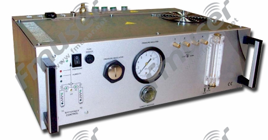
*ਐਂਟੀਨਾ ਵੇਵਗਾਈਡ ਡੀਹਾਈਡਰਟਰ
ਕਿਵੇਂ ਕਰਦਾ ਹੈ ਵੇਵਗਾਈਡ ਡੀਹਾਈਡਰਟਰ ਕੰਮ ਕਰਨ?
ਵੇਵਗਾਈਡ ਡੀਹਾਈਡ੍ਰੇਟਰ ਦੀ ਵਰਤੋਂ ਆਪਣੇ ਲਈ ਸੁੱਕੀ ਕੰਪਰੈੱਸਡ ਹਵਾ ਅਤੇ ਸਿਗਨਲ ਟਰਾਂਸਮਿਸ਼ਨ ਟਾਵਰਾਂ (ਜਿਵੇਂ ਕਿ ਮਾਈਕ੍ਰੋਵੇਵ, ਰਾਡਾਰ, ਐਂਟੀਨਾ ਸਿਸਟਮ, ਟੀਵੀ ਸੈਟੇਲਾਈਟ ਗਰਾਊਂਡ) ਅਤੇ ਵੱਖ-ਵੱਖ ਖੇਤਰਾਂ ਵਿੱਚ ਸਬੰਧਤ ਹਿੱਸਿਆਂ ਲਈ ਕੀਤੀ ਜਾਂਦੀ ਹੈ। ਇਹ ਧਿਆਨ ਦੇਣ ਯੋਗ ਹੈ ਕਿ ਸਿਗਨਲ ਪ੍ਰਸਾਰਣ ਦੀ ਗੁਣਵੱਤਾ ਨੂੰ ਯਕੀਨੀ ਬਣਾਉਣ ਲਈ, ਜਨਰਲ ਵੇਵਗਾਈਡ ਡੀਹਾਈਡਰਟਰ fmuser.-net ਦੁਆਰਾ ਪ੍ਰਦਾਨ ਕੀਤਾ ਗਿਆ ਕੰਪਰੈੱਸਡ ਹਵਾ ਦਾ ਦਬਾਅ ਵਾਯੂਮੰਡਲ ਦੇ ਦਬਾਅ ਤੋਂ ਵੱਧ ਹੋਵੇਗਾ। ਇੱਕ ਪਾਸੇ, ਇਹ ਪਾਣੀ ਨੂੰ ਦਾਖਲ ਹੋਣ ਤੋਂ ਰੋਕਦਾ ਹੈ, ਹਵਾ ਦੇ ਸੰਘਣੇਪਣ ਤੋਂ ਬਚਦਾ ਹੈ, ਅਤੇ ਸਭ ਤੋਂ ਸੁੱਕਾ ਪ੍ਰਭਾਵ ਪ੍ਰਾਪਤ ਕਰਦਾ ਹੈ;![]() ਦੂਜੇ ਪਾਸੇ, ਇਹ ਮੌਸਮ ਦੇ ਪ੍ਰਭਾਵ ਤੋਂ ਬਚਦਾ ਹੈ। ਇੰਟੈਗਰਲ ਕੰਪ੍ਰੈਸਰ ਦੇ ਨਿਰੰਤਰ ਸੰਚਾਲਨ ਦੀ ਬਜਾਏ ਸਟਾਪ-ਸਟਾਰਟ ਚੱਕਰ ਨੂੰ ਯਕੀਨੀ ਬਣਾਉਣ ਲਈ ਵੇਵਗਾਈਡ ਡੀਹਾਈਡਰਟਰ ਵਿੱਚ ਇੱਕ ਛੋਟਾ ਦਬਾਅ ਵਾਲਾ ਭਾਂਡਾ ਸਥਾਪਿਤ ਕੀਤਾ ਗਿਆ ਹੈ।
ਦੂਜੇ ਪਾਸੇ, ਇਹ ਮੌਸਮ ਦੇ ਪ੍ਰਭਾਵ ਤੋਂ ਬਚਦਾ ਹੈ। ਇੰਟੈਗਰਲ ਕੰਪ੍ਰੈਸਰ ਦੇ ਨਿਰੰਤਰ ਸੰਚਾਲਨ ਦੀ ਬਜਾਏ ਸਟਾਪ-ਸਟਾਰਟ ਚੱਕਰ ਨੂੰ ਯਕੀਨੀ ਬਣਾਉਣ ਲਈ ਵੇਵਗਾਈਡ ਡੀਹਾਈਡਰਟਰ ਵਿੱਚ ਇੱਕ ਛੋਟਾ ਦਬਾਅ ਵਾਲਾ ਭਾਂਡਾ ਸਥਾਪਿਤ ਕੀਤਾ ਗਿਆ ਹੈ।![]()
ਡਿਫਰੈਂਸ਼ੀਅਲ ਪ੍ਰੈਸ਼ਰ ਸਵਿੱਚ ਕੰਪ੍ਰੈਸਰ ਦੇ ਸੰਚਾਲਨ ਨੂੰ ਨਿਯੰਤਰਿਤ ਕਰਦਾ ਹੈ। ਕੰਟੇਨਰ ਉੱਚੇ ਦਬਾਅ 'ਤੇ ਸੁੱਕੀ ਹਵਾ ਨੂੰ ਸਟੋਰ ਕਰਦਾ ਹੈ ਅਤੇ ਰੈਗੂਲੇਟਰ ਦੁਆਰਾ ਨਿਰਧਾਰਤ ਘੱਟ ਦਬਾਅ 'ਤੇ ਵੇਵਗਾਈਡ ਵਿੱਚ ਪੰਪ ਕੀਤਾ ਜਾਂਦਾ ਹੈ। ਵਰਤਮਾਨ ਵਿੱਚ, ਮਾਰਕੀਟ ਵਿੱਚ ਬਹੁਤ ਸਾਰੇ ਵੇਵਗਾਈਡ ਡੀਹਾਈਡਰੇਟਰਾਂ ਵਿੱਚ ਬਿਲਟ-ਇਨ ਇਲੈਕਟ੍ਰਾਨਿਕ ਟਾਈਮਿੰਗ ਅਤੇ ਨਮੀ ਨਿਗਰਾਨੀ ਪ੍ਰਣਾਲੀਆਂ ਹਨ, ਜੋ ਕਿ ਤੇਜ਼ ਰਫਤਾਰ ਨਾਲ ਵੇਵਗਾਈਡ ਡੀਹਾਈਡਰੇਟਰਾਂ ਦੀਆਂ ਕੁਝ ਅਚਾਨਕ ਸਮੱਸਿਆਵਾਂ ਦਾ ਪਤਾ ਲਗਾ ਸਕਦੀਆਂ ਹਨ, ਯਾਨੀ ਸੁੱਕੀ ਹਵਾ ਦੀ ਨਾਕਾਫ਼ੀ ਸਟੋਰੇਜ ਕਾਰਨ ਹੋਣ ਵਾਲੀ ਸਮੱਸਿਆ। ਰੇ ਦੀ ਖੋਜ ਦੇ ਆਧਾਰ 'ਤੇ, ਓਪਰੇਟਰ ਇਹ ਯਕੀਨੀ ਬਣਾਉਣ ਲਈ ਜਾਣਬੁੱਝ ਕੇ ਥੋੜ੍ਹੀ ਜਿਹੀ ਹਵਾ ਪੇਸ਼ ਕਰ ਸਕਦਾ ਹੈ ਕਿ ਵੇਵਗਾਈਡ ਡੀਹਾਈਡ੍ਰੇਟਰ ਦੇ ਲਾਭਾਂ ਨੂੰ ਵੱਧ ਤੋਂ ਵੱਧ ਕਰਨ ਲਈ ਲੋੜ ਅਨੁਸਾਰ ਵੇਵਗਾਈਡ ਸਿਸਟਮ ਵਿੱਚ ਹਵਾ ਨੂੰ ਨਿਯਮਿਤ ਤੌਰ 'ਤੇ ਬਦਲਿਆ ਜਾਵੇ।![]()
ਇਸੇ ਵੇਵਗਾਈਡ ਡੀਹਾਈਡਰਟਰ ਮਹੱਤਵਪੂਰਨ ਹੈ?
ਕਿਉਂਕਿ ਵੇਵਗਾਈਡ ਵਿਚਲੇ ਕਣ ਪ੍ਰਤੀਬਿੰਬ ਅਤੇ ਸਿਗਨਲ ਦੇ ਨੁਕਸਾਨ ਜਾਂ ਅਟੈਨਯੂਏਸ਼ਨ ਦਾ ਕਾਰਨ ਬਣਦੇ ਹਨ, ਡੀਹਾਈਡ੍ਰੇਟਰ ਵੇਵਗਾਈਡ ਵਿੱਚ ਇੱਕ ਸਾਫ਼, ਸੁੱਕਾ, ਅਤੇ ਕਣ-ਮੁਕਤ ਵਾਤਾਵਰਣ ਰੱਖ ਸਕਦਾ ਹੈ, ਅਤੇ ਫੀਡ ਪਾਈਪ ਵਿੱਚ ਹਵਾ ਦਾ ਪ੍ਰਵਾਹ ਕਰ ਸਕਦਾ ਹੈ, ਤਾਂ ਜੋ ਐਂਟੀਨਾ ਐਸਡਬਲਯੂਆਰ ਨੂੰ ਰੋਕਿਆ ਜਾ ਸਕੇ। ਬਹੁਤ ਜ਼ਿਆਦਾ ਹੋਣਾ ਜਾਂ ਨਮੀ ਦੇ ਕਾਰਨ ਤਾਰ ਦਾ ਸ਼ਾਰਟ-ਸਰਕਟ ਹੋਣਾ। ਇਸ ਲਈ, ਵੇਵਗਾਈਡ ਡੀਹਾਈਡਰਟਰ ਜ਼ਿਆਦਾਤਰ ਸੰਚਾਰ ਕਾਰਜਾਂ ਵਿੱਚ ਇੱਕ ਮਹੱਤਵਪੂਰਨ ਭੂਮਿਕਾ ਨਿਭਾਉਂਦਾ ਹੈ।![]()
ਇਲੈਕਟ੍ਰੀਕਲ ਕੰਟਰੋਲ ਪੈਨਲ ਭਾਗ
ਇਲੈਕਟ੍ਰੀਕਲ ਕੰਟਰੋਲ ਪੈਨਲਾਂ ਦੇ ਹਿੱਸੇ ਵਿੱਚ, 6 ਪ੍ਰਾਇਮਰੀ ਉਪਕਰਣ ਸ਼ਾਮਲ ਕੀਤੇ ਗਏ ਹਨ, ਅਤੇ ਉਹ ਹਨ (ਵਿਜ਼ਿਟ ਕਰਨ ਲਈ ਕਲਿੱਕ ਕਰੋ):
- ਚਾਕੂ ਸਵਿੱਚ
- ਬਿਜਲੀ ਮੀਟਰ
- ਪਾਵਰ ਅਤੇ ਐਨਰਜੀ ਮਾਨੀਟਰਿੰਗ ਮੀਟਰ
- ਸਰਜ ਪ੍ਰੋਟੈਕਸ਼ਨ ਡਿਵਾਈਸ
- ਸਰਕਟ ਬਰੇਕਰ
- ਪ੍ਰੋਗਰਾਮਮੇਬਲ ਲਾਜਿਕ ਕੰਟਰੋਲਰ
*ਇੱਕ ਦੋ-ਪੋਲ ਚਾਕੂ ਸਵਿੱਚ
ਕਿਵੇਂ ਕਰਦਾ ਹੈ ਚਾਕੂ ਸਵਿੱਚ ਕੰਮ ਕਰਨ?
ਇੱਕ ਚਾਕੂ ਸਵਿੱਚ (ਜਿਸ ਨੂੰ ਚਾਕੂ ਸਵਿੱਚ ਜਾਂ ਡਿਸਕਨੈਕਟਰ ਵੀ ਕਿਹਾ ਜਾਂਦਾ ਹੈ) ਇੱਕ ਕਿਸਮ ਦਾ ਸਵਿੱਚ ਹੁੰਦਾ ਹੈ ਜਿਸ ਵਿੱਚ ਚਲਦੇ ਸੰਪਰਕ - ਚਾਕੂ ਸਵਿੱਚ, ਜੋ ਕਿ ਸਥਿਰ ਸੰਪਰਕ ਨਾਲ ਪਾੜਾ (ਜਾਂ ਵੱਖ ਕੀਤਾ ਜਾਂਦਾ ਹੈ) - ਜੋੜਨ (ਜਾਂ ਡਿਸਕਨੈਕਟ) ਕਰਨ ਲਈ ਅਧਾਰ 'ਤੇ ਚਾਕੂ ਧਾਰਕ ਹੁੰਦਾ ਹੈ। ਸਰਕਟ ਇੱਕ ਚਾਕੂ ਸਵਿੱਚ ਮੈਨੂਅਲ ਕੰਟਰੋਲ ਉਪਕਰਣ ਵਿੱਚ ਸਭ ਤੋਂ ਸਧਾਰਨ ਅਤੇ ਵਿਆਪਕ ਤੌਰ 'ਤੇ ਵਰਤੇ ਜਾਣ ਵਾਲੇ ਘੱਟ-ਵੋਲਟੇਜ ਬਿਜਲੀ ਉਪਕਰਣਾਂ ਵਿੱਚੋਂ ਇੱਕ ਹੈ। ਇਹ ਆਮ ਤੌਰ 'ਤੇ AC ਅਤੇ DC ਘੱਟ-ਵੋਲਟੇਜ (500V ਤੋਂ ਵੱਧ ਨਹੀਂ) ਸਰਕਟਾਂ ਵਿੱਚ ਵਰਤਿਆ ਜਾਂਦਾ ਹੈ ਜਿਨ੍ਹਾਂ ਨੂੰ fmuser.-net ਕੱਟਣ ਅਤੇ ਅਕਸਰ ਬੰਦ ਕਰਨ ਦੀ ਲੋੜ ਨਹੀਂ ਹੁੰਦੀ ਹੈ। ਰੇਟ ਕੀਤੀ ਵੋਲਟੇਜ ਦੇ ਤਹਿਤ, ਇਸਦਾ ਕਾਰਜਸ਼ੀਲ ਕਰੰਟ ਰੇਟ ਕੀਤੇ ਮੁੱਲ fmuser.-net ਤੋਂ ਵੱਧ ਨਹੀਂ ਹੋ ਸਕਦਾ ਹੈ। ਮਸ਼ੀਨ ਟੂਲ ਵਿੱਚ, ਚਾਕੂ ਸਵਿੱਚ ਨੂੰ ਮੁੱਖ ਤੌਰ 'ਤੇ ਪਾਵਰ ਸਵਿੱਚ ਵਜੋਂ ਵਰਤਿਆ ਜਾਂਦਾ ਹੈ, ਇਹ ਆਮ ਤੌਰ 'ਤੇ ਮੋਟਰ ਦੇ ਕਾਰਜਸ਼ੀਲ ਕਰੰਟ ਨੂੰ ਚਾਲੂ ਜਾਂ ਕੱਟਣ ਲਈ ਨਹੀਂ ਵਰਤਿਆ ਜਾਂਦਾ ਹੈ। ਆਮ ਤੌਰ 'ਤੇ ਵਰਤੇ ਜਾਣ ਵਾਲੇ ਚਾਕੂ ਸਵਿੱਚ ਹਨ ਐਚਡੀ ਟਾਈਪ ਸਿੰਗਲ ਥ੍ਰੋ ਨਾਈਫ਼ ਸਵਿੱਚ, ਐਚਐਸ ਟਾਈਪ ਡਬਲ ਥ੍ਰੋ ਨਾਈਫ਼ ਸਵਿੱਚ (ਨਾਈਫ਼ ਸਵਿੱਚ), ਐਚਆਰ ਟਾਈਪ ਫਿਊਜ਼ ਨਾਈਫ਼ ਸਵਿੱਚ, ਐਚਜ਼ਡ ਟਾਈਪ ਕੰਬੀਨੇਸ਼ਨ ਸਵਿੱਚ, ਐਚ.ਕੇ ਟਾਈਪ ਨਾਈਫ਼ ਸਵਿੱਚ, ਐਚਵਾਈ ਟਾਈਪ ਰਿਵਰਸ ਸਵਿੱਚ, ਅਤੇ ਐਚਐਚ ਟਾਈਪ ਆਈਰਨ ਕੇਸ। ਸਵਿੱਚ, ਆਦਿ, ਰੇ-ਫਮੂਜ਼ਰ ਕਹਿੰਦਾ ਹੈ।![]()
ਇਸੇ ਚਾਕੂ ਸਵਿੱਚ ਮਹੱਤਵਪੂਰਨ ਹੈ?
- ਚਾਕੂ ਸਵਿੱਚ ਸਰਕਟ ਅਤੇ ਸਾਜ਼ੋ-ਸਾਮਾਨ ਦੇ ਰੱਖ-ਰਖਾਅ ਦੀ ਸੁਰੱਖਿਆ ਨੂੰ ਯਕੀਨੀ ਬਣਾਉਣ ਲਈ ਜਾਂ ਰੇਟ ਕੀਤੇ ਕਰੰਟ ਤੋਂ ਹੇਠਾਂ ਲੋਡ ਨੂੰ ਕਦੇ-ਕਦਾਈਂ ਜੋੜਨ ਅਤੇ ਤੋੜਨ ਲਈ ਪਾਵਰ ਸਪਲਾਈ ਨੂੰ ਅਲੱਗ ਕਰਦਾ ਹੈ।
- ਚਾਕੂ ਸਵਿੱਚ ਲੋਡ ਨੂੰ ਤੋੜਦਾ ਹੈ, ਜਿਵੇਂ ਕਿ ਛੋਟੀ ਸਮਰੱਥਾ ਵਾਲੇ ਘੱਟ-ਵੋਲਟੇਜ ਸਰਕਟ ਨੂੰ ਕਦੇ-ਕਦਾਈਂ ਜੋੜਨਾ ਅਤੇ ਤੋੜਨਾ ਜਾਂ ਛੋਟੀ ਸਮਰੱਥਾ ਵਾਲੀ ਮੋਟਰ ਨੂੰ ਸਿੱਧਾ ਚਾਲੂ ਕਰਨਾ।

- ਜਦੋਂ ਚਾਕੂ ਸਵਿੱਚ ਬੰਦ ਸਥਿਤੀ ਵਿੱਚ ਹੁੰਦਾ ਹੈ, ਤਾਂ ਇਹ ਸਪੱਸ਼ਟ ਤੌਰ 'ਤੇ ਦੇਖਿਆ ਜਾ ਸਕਦਾ ਹੈ, ਜੋ ਸਰਕਟ ਰੱਖ-ਰਖਾਅ ਦੇ ਕਰਮਚਾਰੀਆਂ ਦੀ ਸੁਰੱਖਿਆ ਨੂੰ ਯਕੀਨੀ ਬਣਾ ਸਕਦਾ ਹੈ।
ਬਿਜਲੀ ਸਪਲਾਈ ਨੂੰ ਅਲੱਗ ਕਰਨ ਵਾਲੇ ਚਾਕੂ ਸਵਿੱਚ ਨੂੰ ਡਿਸਕਨੈਕਟਿੰਗ ਸਵਿੱਚ ਵੀ ਕਿਹਾ ਜਾਂਦਾ ਹੈ। ਆਈਸੋਲੇਸ਼ਨ ਲਈ ਚਾਕੂ ਸਵਿੱਚ ਆਮ ਤੌਰ 'ਤੇ ਇੱਕ ਨੋ-ਲੋਡ ਔਨ-ਆਫ ਡਿਵਾਈਸ ਹੈ, ਜੋ ਸਿਰਫ "ਨਗਨ ਕਰੰਟ" ਬਣਾ ਜਾਂ ਤੋੜ ਸਕਦਾ ਹੈ (ਵੋਲਟੇਜ, ਛੋਟੀ ਕੇਬਲ, ਜਾਂ ਵੋਲਟੇਜ ਟ੍ਰਾਂਸਫਾਰਮਰ ਵਾਲੀ ਬੱਸ ਦੇ ਕੈਪੇਸਿਟਿਵ ਕਰੰਟ ਨੂੰ ਦਰਸਾਉਂਦਾ ਹੈ)। ਕੁਝ ਚਾਕੂ ਸਵਿੱਚਾਂ ਵਿੱਚ ਕੁਝ ਔਨ-ਆਫ ਸਮਰੱਥਾਵਾਂ ਹੁੰਦੀਆਂ ਹਨ। ਜਦੋਂ ਉਹਨਾਂ ਦੀ ਆਨ-ਆਫ ਸਮਰੱਥਾ ਲੋੜੀਂਦੇ ਆਨ-ਆਫ ਕਰੰਟ ਲਈ ਢੁਕਵੀਂ ਹੁੰਦੀ ਹੈ, ਤਾਂ ਉਹ ਗੈਰ-ਨੁਕਸ ਵਾਲੀਆਂ ਸਥਿਤੀਆਂ ਵਿੱਚ ਇਲੈਕਟ੍ਰੀਕਲ ਉਪਕਰਨ fmuser-net ਜਾਂ ਪੂਰੇ ਉਪਕਰਣ ਦੇ ਹਿੱਸੇ ਨੂੰ ਚਾਲੂ ਜਾਂ ਬੰਦ ਕਰ ਸਕਦੇ ਹਨ। ਡਿਸਕਨੈਕਟਰ ਵਜੋਂ ਵਰਤੇ ਜਾਣ ਵਾਲੇ ਚਾਕੂ ਸਵਿੱਚ ਨੂੰ ਆਈਸੋਲੇਸ਼ਨ ਫੰਕਸ਼ਨ ਨੂੰ ਪੂਰਾ ਕਰਨਾ ਚਾਹੀਦਾ ਹੈ, ਯਾਨੀ, ਸਵਿੱਚ ਫ੍ਰੈਕਚਰ ਸਪੱਸ਼ਟ ਹੈ, ਅਤੇ ਫ੍ਰੈਕਚਰ ਦੂਰੀ ਯੋਗ ਹੈ। ਬਿਜਲਈ ਸਾਜ਼ੋ-ਸਾਮਾਨ ਦੇ ਰੱਖ-ਰਖਾਅ ਦੌਰਾਨ, ਇਸ ਨੂੰ ਲਾਈਵ ਹਿੱਸੇ ਤੋਂ ਵੱਖ ਕਰਨ ਲਈ ਬਿਜਲੀ ਸਪਲਾਈ ਨੂੰ ਕੱਟਣਾ ਜ਼ਰੂਰੀ ਹੈ, ਅਤੇ ਇੱਕ ਪ੍ਰਭਾਵੀ ਅਲੱਗ-ਥਲੱਗ ਦੂਰੀ ਬਣਾਈ ਰੱਖੋ। ਰੇ ਨੇ ਕੀ ਪਾਇਆ: ਇਹ ਲੋੜੀਂਦਾ ਹੈ ਕਿ ਸਪਲਿਟ ਭਾਗਾਂ ਦੇ ਵਿਚਕਾਰ ਓਵਰਵੋਲਟੇਜ ਦਾ ਸਾਮ੍ਹਣਾ ਕਰਨ ਵਾਲੇ ਵੋਲਟੇਜ ਪੱਧਰ ਦਾ ਸਾਮ੍ਹਣਾ ਕੀਤਾ ਜਾ ਸਕਦਾ ਹੈ। ਜਿਵੇਂ ਰੇ ਕਹਿੰਦਾ ਹੈ। ਚਾਕੂ ਸਵਿੱਚ ਦੀ ਵਰਤੋਂ ਪਾਵਰ ਸਪਲਾਈ ਨੂੰ ਅਲੱਗ ਕਰਨ ਲਈ ਇੱਕ ਸਵਿਚਿੰਗ ਡਿਵਾਈਸ ਵਜੋਂ ਕੀਤੀ ਜਾਂਦੀ ਹੈ।
ਚਾਕੂ ਸਵਿੱਚ ਅਤੇ ਫਿਊਜ਼ ਇੱਕ ਯੂਨਿਟ ਬਣਾਉਣ ਲਈ ਲੜੀ ਵਿੱਚ ਜੁੜੇ ਹੋਏ ਹਨ, ਜਿਸ ਨੂੰ ਚਾਕੂ ਸਵਿੱਚ ਫਿਊਜ਼ ਗਰੁੱਪ ਜਾਂ ਡਿਸਕਨੈਕਟਿੰਗ ਸਵਿੱਚ ਫਿਊਜ਼ ਗਰੁੱਪ ਕਿਹਾ ਜਾਂਦਾ ਹੈ; ਜਦੋਂ ਚਾਕੂ ਸਵਿੱਚ ਦਾ ਚੱਲਦਾ ਹਿੱਸਾ (ਮੂਵਿੰਗ ਕਾਂਟੈਕਟ) ਫਿਊਜ਼ ਲਿੰਕ ਦੇ ਨਾਲ ਫਿਊਜ਼ ਲਿਜਾਣ ਵਾਲੇ ਹਿੱਸਿਆਂ ਦਾ ਬਣਿਆ ਹੁੰਦਾ ਹੈ, ਤਾਂ ਇਸ ਨੂੰ ਫਿਊਜ਼ ਨਾਈਫ ਸਵਿੱਚ ਜਾਂ ਫਿਊਜ਼ ਡਿਸਕਨੈਕਟਿੰਗ ਸਵਿੱਚ fmuser ਕਿਹਾ ਜਾਂਦਾ ਹੈ। ਜਾਲ ਸਵਿੱਚ ਫਿਊਜ਼ ਨੂੰ ਸਹਾਇਕ ਭਾਗਾਂ ਨਾਲ ਜੋੜਿਆ ਜਾਂਦਾ ਹੈ, ਜਿਵੇਂ ਕਿ ਓਪਰੇਟਿੰਗ ਲੀਵਰ, ਸਪਰਿੰਗ, ਚਾਪ ਚਾਕੂ, ਆਦਿ। ਲੋਡ ਸਵਿੱਚ ਵਿੱਚ ਗੈਰ-ਨੁਕਸਦਾਰ ਸਥਿਤੀਆਂ ਵਿੱਚ ਲੋਡ ਕਰੰਟ ਨੂੰ ਚਾਲੂ ਜਾਂ ਬੰਦ ਕਰਨ ਦੀ ਸਮਰੱਥਾ ਹੁੰਦੀ ਹੈ ਅਤੇ ਇੱਕ ਖਾਸ ਸ਼ਾਰਟ-ਸਰਕਟ ਸੁਰੱਖਿਆ ਫੰਕਸ਼ਨ ਹੁੰਦਾ ਹੈ।![]()
2. ਬਿਜਲੀ ਮੀਟਰ
*ਇੱਕ ਰਵਾਇਤੀ ਬਿਜਲੀ ਮੀਟਰ
ਕਿਵੇਂ ਕਰਦਾ ਹੈ ਬਿਜਲੀ ਮੀਟਰ ਕੰਮ ਕਰਨ?
ਇੱਕ ਬਿਜਲੀ ਮੀਟਰ (ਇੱਕ ਬਿਜਲੀ ਮੀਟਰ, ਇਲੈਕਟ੍ਰਿਕ ਮੀਟਰ, ਇਲੈਕਟ੍ਰੀਕਲ ਮੀਟਰ, ਜਾਂ ਊਰਜਾ ਮੀਟਰ ਵਜੋਂ ਵੀ ਜਾਣਿਆ ਜਾਂਦਾ ਹੈ) ਰਿਹਾਇਸ਼ੀ, ਕਾਰੋਬਾਰ, ਜਾਂ ਇਲੈਕਟ੍ਰਿਕ ਉਪਕਰਣ fmuser-net ਦੁਆਰਾ ਖਪਤ ਕੀਤੀ ਬਿਜਲੀ ਊਰਜਾ ਨੂੰ ਮਾਪਣ ਲਈ ਇੱਕ ਉਪਕਰਣ ਹੈ। ਬਿਜਲੀ ਮੀਟਰਾਂ ਨੂੰ ਡਿਜੀਟਲ ਮੀਟਰ ਅਤੇ ਐਨਾਲਾਗ ਮੀਟਰਾਂ ਵਿੱਚ ਵੰਡਿਆ ਗਿਆ ਹੈ। ਬਿਜਲੀ ਮੀਟਰਾਂ ਦੀ ਸਥਾਪਨਾ ਅਤੇ ਅੰਤਮ ਬਿਲਿੰਗ ਆਮ ਤੌਰ 'ਤੇ ਬਿਜਲੀ ਕੰਪਨੀਆਂ ਲਈ ਹੁੰਦੀ ਹੈ। ਬਿਜਲੀ ਕੰਪਨੀਆਂ ਦਾ ਸਟਾਫ ਬਿਜਲੀ ਮੀਟਰ ਲਗਾਉਣਗੇ ਜਿੱਥੇ ਉਨ੍ਹਾਂ ਨੂੰ ਬਿਜਲੀ ਮੀਟਰਾਂ ਦੀ ਵਰਤੋਂ ਕਰਨ ਦੀ ਜ਼ਰੂਰਤ ਹੈ, ਅਤੇ ਸਮੇਂ-ਸਮੇਂ 'ਤੇ ਮੀਟਰਾਂ 'ਤੇ ਮਾਪਦੰਡਾਂ ਰਾਹੀਂ ਉਪਭੋਗਤਾਵਾਂ ਦੀ ਨਿਗਰਾਨੀ ਅਤੇ ਚਾਰਜ ਕਰਨਗੇ। ਜਦੋਂ ਤੁਹਾਡੇ ਘਰ ਨੂੰ ਇੱਕ ਤਾਰ ਤੋਂ ਬਿਜਲੀ ਮਿਲਦੀ ਹੈ, ਤਾਂ ਮੀਟਰ ਵਿੱਚ ਪਿਨੀਅਨਾਂ ਦਾ ਇੱਕ ਸੈੱਟ ਚਲਦਾ ਹੈ। ਕ੍ਰਾਂਤੀ ਉਸ ਡਾਇਲ ਦੁਆਰਾ ਰਿਕਾਰਡ ਕੀਤੀ ਜਾਂਦੀ ਹੈ ਜਦੋਂ ਤੁਸੀਂ ਮੀਟਰ fmuser.-net ਨੂੰ ਦੇਖਦੇ ਹੋ। ਰੋਟੇਸ਼ਨਲ ਗਤੀ ਖਪਤ ਸ਼ਕਤੀ ਦੁਆਰਾ ਨਿਰਧਾਰਤ ਕੀਤੀ ਜਾਂਦੀ ਹੈ। ਰੇ ਦਾ ਕਹਿਣਾ ਹੈ ਕਿ ਕੁਝ ਹੋਰ ਊਰਜਾ ਮਾਪਣ ਵਾਲੇ ਯੰਤਰਾਂ ਦਾ ਕੰਮ ਕਰਨ ਦਾ ਸਿਧਾਂਤ, ਇਲੈਕਟ੍ਰਿਕ ਮੀਟਰਾਂ ਦੇ ਸਮਾਨ ਹਨ, ਜਿਵੇਂ ਕਿ ਗੈਸ ਮੀਟਰ, ਪਾਈਪਲਾਈਨ ਵਿੱਚ ਚਲਦੀ ਗੈਸ ਦੇ ਬਲ ਨੂੰ ਮਾਪਣ ਲਈ ਹੈ। ਗੈਸ ਦੇ ਵਹਾਅ ਦੇ ਵਧਣ ਨਾਲ, ਡਾਇਲ ਤੇਜ਼ੀ ਨਾਲ ਘੁੰਮਦਾ ਹੈ, ਜਿਸਦਾ ਮਤਲਬ ਹੈ ਕਿ ਜ਼ਿਆਦਾ ਗੈਸ ਦੀ ਵਰਤੋਂ ਕੀਤੀ ਜਾਂਦੀ ਹੈ। ਇਹ ਧਿਆਨ ਦੇਣ ਯੋਗ ਹੈ ਕਿ ਬਿਜਲੀ ਦੀ ਰੀਡਿੰਗ ਅਕਸਰ kWh ਵਿੱਚ ਹੁੰਦੀ ਹੈ ਅਤੇ ਭਾਵੇਂ ਇਹ ਇੱਕ ਡਿਜੀਟਲ ਮੀਟਰ ਹੋਵੇ ਜਾਂ ਐਨਾਲਾਗ ਮੀਟਰ, ਡਿਸਪਲੇ 'ਤੇ ਦਿਖਾਈ ਗਈ ਬਿਜਲੀ ਦੀ kWh ਦੀ ਖਪਤ ਨੂੰ ਰੀਸੈਟ ਨਹੀਂ ਕੀਤਾ ਜਾਵੇਗਾ। ਜਦੋਂ ਬਿਜਲੀ ਕੰਪਨੀ ਦਾ ਸਟਾਫ ਮੀਟਰ 'ਤੇ ਪ੍ਰਦਰਸ਼ਿਤ ਮੌਜੂਦਾ ਮਹੀਨੇ (ਹਫ਼ਤੇ) ਵਿੱਚ ਖਪਤ ਹੋਈ ਬਿਜਲੀ ਨੂੰ ਪੜ੍ਹਦਾ ਹੈ, ਤਾਂ ਉਨ੍ਹਾਂ ਨੂੰ ਹਰ ਘਰ ਦੇ ਬਿੱਲ ਦੀ ਰਕਮ ਅਤੇ ਚਾਰਜ ਦੀ ਗਣਨਾ ਕਰਨ ਲਈ ਮਹੀਨੇ ਦੇ ਅੰਤ ਤੱਕ ਨੰਬਰ ਘਟਾਉਣ ਦੀ ਲੋੜ ਹੁੰਦੀ ਹੈ।
ਇਸੇ ਬਿਜਲੀ ਮੀਟਰ ਮਹੱਤਵਪੂਰਨ ਹੈ?
ਹੋ ਸਕਦਾ ਹੈ ਕਿ ਤੁਸੀਂ ਮੀਟਰ 'ਤੇ ਪੈਰਾਮੀਟਰਾਂ ਦੀਆਂ ਤਬਦੀਲੀਆਂ ਵੱਲ ਖਾਸ ਧਿਆਨ ਨਾ ਦਿਓ, ਪਰ ਤੁਹਾਨੂੰ ਮੀਟਰ ਪੈਨਲ 'ਤੇ ਪ੍ਰਦਰਸ਼ਿਤ ਸੰਖਿਆਵਾਂ ਨੂੰ ਕਿਵੇਂ ਵੇਖਣਾ ਹੈ, ਇਹ ਪਤਾ ਹੋਣਾ ਚਾਹੀਦਾ ਹੈ, ਤਾਂ ਜੋ ਤੁਸੀਂ ਨਿਗਰਾਨੀ ਕਰ ਸਕੋ ਕਿ ਤੁਸੀਂ ਪਿਛਲੇ ਮਹੀਨੇ ਦੇ ਮੁਕਾਬਲੇ ਹਰ ਮਹੀਨੇ ਜਾਂ ਹਫ਼ਤੇ ਵਿੱਚ ਕਿੰਨੀ ਊਰਜਾ ਦੀ ਵਰਤੋਂ ਕਰਦੇ ਹੋ। ਜਾਂ ਹਫ਼ਤਾ, ਅਤੇ ਬਿਲ ਦੀ ਰਕਮ ਦੀ ਜਾਂਚ ਕਰੋ ਜੋ ਤੁਹਾਨੂੰ ਪਾਵਰ ਕੰਪਨੀ ਦੁਆਰਾ ਅਦਾ ਕਰਨ ਦੀ ਲੋੜ ਹੈ ਅਤੇ ਕੁਝ ਸਧਾਰਨ ਗਣਨਾਵਾਂ ਦੁਆਰਾ ਆਪਣੇ ਆਪ ਦੀ ਗਣਨਾ ਕਰੋ, ਇਹ ਯਕੀਨੀ ਬਣਾਉਣ ਲਈ ਕਿ ਬੇਲੋੜੇ ਪੈਸੇ ਖਰਚ ਨਾ ਕਰੋ।
ਹਾਲਾਂਕਿ ਮੌਜੂਦਾ ਸਮੇਂ ਵਿੱਚ ਬਜ਼ਾਰ ਵਿੱਚ ਬਿਜਲੀ ਮੀਟਰਾਂ ਦੀਆਂ ਕਿਸਮਾਂ ਇੱਕਸਾਰ ਨਹੀਂ ਹਨ, ਪਰ ਬਿਜਲੀ ਖਪਤਕਾਰਾਂ ਅਤੇ ਬਿਜਲੀ ਊਰਜਾ ਸਪਲਾਇਰਾਂ ਦੋਵਾਂ ਲਈ ਡਿਜੀਟਲ ਬਿਜਲੀ ਮੀਟਰਾਂ ਦੀ ਵਰਤੋਂ ਕਰਨ ਦੇ ਬਹੁਤ ਸਾਰੇ ਫਾਇਦੇ ਹਨ। ਖਪਤਕਾਰਾਂ ਲਈ, ਮਜ਼ਬੂਤ ਮੰਗ ਦੀ ਮਿਆਦ (ਸ਼ਾਮ 6:00 - 11:00 ਵਜੇ) ਵਿੱਚ ਬਿਜਲੀ ਦੀ ਕੀਮਤ ਅਕਸਰ ਘੱਟ ਮੰਗ ਦੀ ਮਿਆਦ (0:00 ਵਜੇ - ਸ਼ਾਮ 7:00 ਵਜੇ) ਨਾਲੋਂ ਘੱਟ ਹੁੰਦੀ ਹੈ। ਜੇਕਰ ਤੁਸੀਂ ਪਰੰਪਰਾਗਤ ਆਟੋਮੈਟਿਕ ਮੀਟਰ ਰੀਡਿੰਗ (AMR) ਦੀ ਵਰਤੋਂ ਕਰਦੇ ਹੋ, ਤਾਂ ਤੁਸੀਂ ਬਿਜਲੀ ਦੇ ਬਿੱਲ 'ਤੇ ਜ਼ਿਆਦਾ ਖਰਚ ਕਰੋਗੇ, ਕਿਉਂਕਿ AMR ਤੁਹਾਡੀ ਬਿਜਲੀ ਦੀ ਖਪਤ ਨੂੰ ਟਰੈਕ ਕਰੇਗਾ ਅਤੇ ਪਾਵਰ ਕੰਪਨੀ ਤੁਹਾਡੇ ਤੋਂ ਪਿਛਲੇ ਸਾਈਕਲ fmuser.-net ਦੀ ਔਸਤ ਕੀਮਤ ਦੇ ਆਧਾਰ 'ਤੇ ਬਿਜਲੀ ਚਾਰਜ ਕਰੇਗੀ। ਡਿਜ਼ੀਟਲ ਮੀਟਰਾਂ ਦੀ ਵਰਤੋਂ ਨਾਲ ਬਿਜਲੀ ਦੀ ਖਪਤ ਦੀ ਸਹੀ ਨਿਗਰਾਨੀ ਕੀਤੀ ਜਾ ਸਕਦੀ ਹੈ ਤਾਂ ਜੋ ਤੁਹਾਡਾ ਪਾਵਰ ਊਰਜਾ ਸਪਲਾਇਰ ਤੁਹਾਡੇ ਦੁਆਰਾ ਵਰਤੀ ਜਾਂਦੀ ਬਿਜਲੀ ਦੀ ਖਾਸ ਸੰਖਿਆ ਦਾ ਪਤਾ ਲਗਾ ਸਕੇ, ਅਤੇ ਇਹ ਵੀ ਨਿਰਧਾਰਤ ਕਰ ਸਕੇ ਕਿ ਤੁਸੀਂ ਬਿਜਲੀ ਦੀ ਵਰਤੋਂ ਕਦੋਂ ਕਰਦੇ ਹੋ, ਤਾਂ ਜੋ ਬੇਲੋੜੇ ਬਿਜਲੀ ਬਿੱਲ ਦੇ ਖਰਚਿਆਂ ਤੋਂ ਬਚਿਆ ਜਾ ਸਕੇ। ਬਿਜਲੀ ਊਰਜਾ ਸਪਲਾਇਰਾਂ ਲਈ, ਸਮਾਰਟ ਮੀਟਰਾਂ ਦੀ ਵਰਤੋਂ ਉਹਨਾਂ ਦੇ ਸਟਾਫ਼ ਲਈ ਸੁਵਿਧਾਜਨਕ ਹੈ। ਹਰੇਕ ਘਰ ਦੁਆਰਾ ਖਪਤ ਕੀਤੀ ਗਈ ਬਿਜਲੀ ਦੀ ਗਿਣਤੀ ਦੀ ਗਿਣਤੀ ਕਰਨ ਦੀ ਬਜਾਏ, ਉਹ ਰਿਮੋਟ ਸੰਚਾਰ ਦੁਆਰਾ ਮੀਟਰ ਪੈਨਲ 'ਤੇ ਮਾਪਦੰਡਾਂ ਨੂੰ ਸਿੱਧਾ ਪੜ੍ਹ ਸਕਦੇ ਹਨ, ਜਿਸ ਨਾਲ ਪਾਵਰ ਕੰਪਨੀਆਂ ਦੀ ਸੰਚਾਲਨ ਲਾਗਤ ਅਤੇ ਮਜ਼ਦੂਰੀ ਦੀ ਲਾਗਤ ਬਹੁਤ ਘੱਟ ਜਾਂਦੀ ਹੈ।![]()
3. ਪਾਵਰ ਨਿਗਰਾਨੀ ਅਤੇ ਨਿਯੰਤਰਣ ਉਪਕਰਨ
* ਵਿੰਡੋ ਟਾਈਪ ਕਰੰਟ ਟ੍ਰਾਂਸਫਾਰਮਰ
ਕਿਸ ਕਰਦਾ ਹੈ ਮੌਜੂਦਾ ਟ੍ਰਾਂਸਫਾਰਮਰ ਕੰਮ ਕਰਨ?
ਕਰੰਟ ਟ੍ਰਾਂਸਫਾਰਮਰ (CT) ਇੱਕ ਕਿਸਮ ਦਾ ਇੰਸਟਰੂਮੈਂਟ ਟ੍ਰਾਂਸਫਾਰਮਰ ਹੈ, ਜੋ ਉੱਚ ਵੋਲਟੇਜ ਕਰੰਟ ਨੂੰ ਘੱਟ ਵੋਲਟੇਜ ਕਰੰਟ ਵਿੱਚ ਬਦਲ ਸਕਦਾ ਹੈ, ਯਾਨੀ ਕਰੰਟ ਨੂੰ ਉੱਚ ਮੁੱਲ ਤੋਂ ਅਨੁਪਾਤਕ ਕਰੰਟ ਵਿੱਚ ਅਤੇ ਫਿਰ ਹੇਠਲੇ ਮੁੱਲ ਵਿੱਚ ਬਦਲ ਸਕਦਾ ਹੈ। ਇਸਦੇ ਕਾਰਜਸ਼ੀਲ ਢਾਂਚੇ ਦੇ ਅਨੁਸਾਰ, ਮੌਜੂਦਾ ਟ੍ਰਾਂਸਫਾਰਮਰਾਂ ਨੂੰ ਇੱਕ ਪੱਟੀ ਕਿਸਮ, ਜ਼ਖ਼ਮ ਦੀ ਕਿਸਮ ਅਤੇ ਵਿੰਡੋ ਕਿਸਮ ਵਿੱਚ ਵੰਡਿਆ ਜਾ ਸਕਦਾ ਹੈ। ਇਸਦੀ ਪ੍ਰਕਿਰਤੀ ਦੇ ਅਨੁਸਾਰ, ਸੀਟੀ ਨੂੰ ਦੋ ਕਿਸਮਾਂ ਵਿੱਚ ਵੰਡਿਆ ਜਾ ਸਕਦਾ ਹੈ: ਸੁਰੱਖਿਆ ਮੌਜੂਦਾ ਟ੍ਰਾਂਸਫਾਰਮਰ ਅਤੇ ਮਾਪਣ ਵਾਲੇ ਮੌਜੂਦਾ ਟ੍ਰਾਂਸਫਾਰਮਰ fmuser-net। ਉਹਨਾਂ ਵਿੱਚੋਂ, ਸੁਰੱਖਿਆ ਕਰੰਟ ਟਰਾਂਸਫਾਰਮਰ ਕਰੰਟ, ਊਰਜਾ ਅਤੇ ਪਾਵਰ (ਦੂਜੇ ਮਾਪਣ ਵਾਲੇ ਉਪਕਰਣਾਂ ਦੇ ਨਾਲ ਇਕੱਠੇ ਵਰਤੇ ਜਾਂਦੇ ਹਨ) ਨੂੰ ਮਾਪਣ ਲਈ ਜ਼ਿੰਮੇਵਾਰ ਹੁੰਦੇ ਹਨ, ਜਦੋਂ ਕਿ ਮੌਜੂਦਾ ਟਰਾਂਸਫਾਰਮਰ ਨੂੰ ਇੱਕ ਟ੍ਰਿਪ ਕੋਇਲ, ਰੀਲੇਅ ਅਤੇ ਹੋਰ ਸੁਰੱਖਿਆ ਉਪਕਰਣਾਂ ਦੇ ਨਾਲ ਵਰਤਿਆ ਜਾਂਦਾ ਹੈ।![]()
ਇਸੇ ਮੌਜੂਦਾ ਟ੍ਰਾਂਸਫਾਰਮਰ ਮਹੱਤਵਪੂਰਨ ਹੈ?
ਮੌਜੂਦਾ ਟ੍ਰਾਂਸਫਾਰਮਰ ਪਾਵਰ ਸਿਸਟਮ ਦੇ ਮਹੱਤਵਪੂਰਨ ਤੱਤਾਂ ਵਿੱਚੋਂ ਇੱਕ ਹੈ, ਜੋ ਕਿ ਉੱਚ ਕਰੰਟ ਅਤੇ ਉੱਚ ਵੋਲਟੇਜ ਦੇ ਮਾਪ ਅਤੇ ਨਿਗਰਾਨੀ ਵਿੱਚ ਵਿਆਪਕ ਤੌਰ 'ਤੇ ਵਰਤਿਆ ਜਾਂਦਾ ਹੈ। ਇੱਕ ਮਿਆਰੀ ਐਮਮੀਟਰ ਦੀ ਵਰਤੋਂ ਕਰਕੇ, AC ਟਰਾਂਸਮਿਸ਼ਨ ਲਾਈਨ ਵਿੱਚ ਵਹਿ ਰਹੇ ਕਰੰਟ ਦੀ ਸੁਰੱਖਿਅਤ ਢੰਗ ਨਾਲ ਨਿਗਰਾਨੀ ਕੀਤੀ ਜਾ ਸਕਦੀ ਹੈ। ਉਦਾਹਰਨ ਲਈ, ਮੌਜੂਦਾ ਟ੍ਰਾਂਸਫਾਰਮਰ ਨੂੰ ਬਹੁਤ ਸਾਰੇ ਵੱਡੇ ਵਪਾਰਕ ਅਤੇ ਉਦਯੋਗਿਕ ਪਾਵਰ ਮੀਟਰਾਂ ਦੇ ਕੋਰ ਡਰਾਈਵਰ ਵਜੋਂ ਵਰਤਿਆ ਜਾ ਸਕਦਾ ਹੈ। ਜਿਵੇਂ ਕਿ ਰੇ ਕਹਿੰਦਾ ਹੈ, ਮੌਜੂਦਾ ਟ੍ਰਾਂਸਫਾਰਮਰਾਂ ਦੀ ਵਰਤੋਂ ਇਹਨਾਂ ਯੰਤਰਾਂ ਨੂੰ ਬਿਜਲੀ ਦੇ ਅਨੁਪਾਤਕ ਕਰੰਟ ਪ੍ਰਦਾਨ ਕਰਨ ਅਤੇ ਉੱਚ ਵੋਲਟੇਜ ਸਰਕਟਾਂ ਤੋਂ ਮਾਪਣ ਵਾਲੇ ਯੰਤਰਾਂ ਨੂੰ ਅਲੱਗ ਕਰਨ ਲਈ ਵੀ ਕੀਤੀ ਜਾਂਦੀ ਹੈ।![]()
4. ਸਰਜ ਪ੍ਰੋਟੈਕਸ਼ਨ ਡਿਵਾਈਸ
* ਸਰਜ ਪ੍ਰੋਟੈਕਸ਼ਨ ਡਿਵਾਈਸ
ਕਿਵੇਂ ਕਰਦਾ ਹੈ ਸਰਜ ਪ੍ਰੋਟੈਕਸ਼ਨ ਡਿਵਾਈਸ ਕੰਮ ਕਰਨ?
ਸਰਜ ਪ੍ਰੋਟੈਕਸ਼ਨ ਸਾਜ਼ੋ-ਸਾਮਾਨ (SPD), ਜਿਸਨੂੰ ਪਹਿਲਾਂ ਅਸਥਾਈ ਵੋਲਟੇਜ ਸਰਜ ਸਪ੍ਰੈਸਰ (TVSS) ਜਾਂ ਸੈਕੰਡਰੀ ਸਰਜ ਸਪ੍ਰੈਸਰ (SSA) ਵਜੋਂ ਜਾਣਿਆ ਜਾਂਦਾ ਸੀ, ਸਭ ਤੋਂ ਵੱਧ ਵਰਤੀ ਜਾਂਦੀ ਅਤੇ ਪ੍ਰਭਾਵਸ਼ਾਲੀ ਕਿਸਮ ਦੀ ਓਵਰਵੋਲਟੇਜ ਸੁਰੱਖਿਆ ਹੈ, ਜੋ ਕਿ ਵੋਲਟੇਜ ਸਪਾਈਕਸ ਨੂੰ ਰੋਕਣ ਲਈ ਤਿਆਰ ਕੀਤੀ ਗਈ ਹੈ fmuser .net ਜਾਂ "transients. ਨੁਕਸਾਨ ਪਹੁੰਚਾਉਣ ਵਾਲੇ ਇਲੈਕਟ੍ਰਾਨਿਕ ਉਪਕਰਣਾਂ ਤੋਂ, ਜੋ ਆਮ ਤੌਰ 'ਤੇ ਲੋਡ ਦੇ ਪਾਵਰ ਸਪਲਾਈ ਸਰਕਟ ਦੇ ਸਮਾਨਾਂਤਰ ਨਾਲ ਜੁੜਿਆ ਹੁੰਦਾ ਹੈ। ਇਲੈਕਟ੍ਰੀਕਲ ਇੰਸਟਾਲੇਸ਼ਨ ਸੁਰੱਖਿਆ ਪ੍ਰਣਾਲੀ ਦੇ ਇੱਕ ਮਹੱਤਵਪੂਰਨ ਹਿੱਸੇ ਦੇ ਰੂਪ ਵਿੱਚ, ਜਦੋਂ ਅਸਥਾਈ ਵੋਲਟੇਜ (ਜਿਵੇਂ ਕਿ ਬਿਜਲੀ ਦੀ ਹੜਤਾਲ ਜਾਂ ਪਾਵਰ ਲਾਈਨ ਦਾ ਨੁਕਸਾਨ) ਸੁਰੱਖਿਆ ਸਰਕਟ 'ਤੇ ਅਚਾਨਕ ਦਿਖਾਈ ਦਿੰਦਾ ਹੈ, ਤਾਂ SPD ਅਸਥਾਈ ਵੋਲਟੇਜ ਨੂੰ ਸੀਮਿਤ ਕਰਦਾ ਹੈ ਅਤੇ ਮੌਜੂਦਾ ਨੂੰ ਵਾਪਸ ਇਸਦੇ ਸਰੋਤ ਜਾਂ ਜ਼ਮੀਨ 'ਤੇ ਟ੍ਰਾਂਸਫਰ ਕਰਦਾ ਹੈ। ਜਦੋਂ ਵੋਲਟੇਜ ਇੱਕ ਨਿਸ਼ਚਿਤ ਬਿੰਦੂ 'ਤੇ ਪਹੁੰਚ ਜਾਂਦੀ ਹੈ, ਤਾਂ ਸਰਜ ਪ੍ਰੋਟੈਕਟਰ ਸੰਖੇਪ ਵਿੱਚ ਇੱਕ ਦਬਾਅ-ਸੰਵੇਦਨਸ਼ੀਲ ਵਾਲਵ ਦੇ ਕਾਰਜ ਦੇ ਕਾਰਨ ਵਾਧੂ ਊਰਜਾ ਨੂੰ ਮੁੜ ਵੰਡ ਸਕਦਾ ਹੈ। ਸਹੀ ਵੋਲਟੇਜ ਦੇ ਨਾਲ, ਕਰੰਟ ਆਮ ਤੌਰ 'ਤੇ ਵਹਿ ਜਾਵੇਗਾ। ਸਰਜ ਪ੍ਰੋਟੈਕਸ਼ਨ ਸਾਜ਼ੋ-ਸਾਮਾਨ fmuser -net ਦੀ ਵਰਤੋਂ ਪਾਵਰ ਨੈਟਵਰਕ ਦੇ ਸਾਰੇ ਪੱਧਰਾਂ 'ਤੇ ਵੀ ਕੀਤੀ ਜਾ ਸਕਦੀ ਹੈ, SPD ਆਮ ਓਪਰੇਟਿੰਗ ਵੋਲਟੇਜ ਦੇ ਅਧੀਨ ਇੱਕ ਉੱਚ ਰੁਕਾਵਟ ਸਥਿਤੀ ਵਿੱਚ ਹੈ ਅਤੇ ਸਿਸਟਮ ਨੂੰ ਪ੍ਰਭਾਵਤ ਨਹੀਂ ਕਰਦਾ ਹੈ। ਜਦੋਂ ਸਰਕਟ 'ਤੇ ਅਸਥਾਈ ਵੋਲਟੇਜ ਹੁੰਦੀ ਹੈ, ਤਾਂ SPD ਆਨ ਸਟੇਟ (ਜਾਂ ਘੱਟ ਰੁਕਾਵਟ) ਵਿੱਚ ਦਾਖਲ ਹੁੰਦਾ ਹੈ ਅਤੇ ਸਰਜ ਕਰੰਟ ਨੂੰ ਵਾਪਸ ਇਸਦੇ ਸਰੋਤ ਜਾਂ ਜ਼ਮੀਨ 'ਤੇ ਟ੍ਰਾਂਸਫਰ ਕਰਦਾ ਹੈ। ਇਹ ਵੋਲਟੇਜ ਜਾਂ ਕਲੈਂਪ ਨੂੰ ਸੁਰੱਖਿਅਤ ਪੱਧਰ ਤੱਕ ਸੀਮਤ ਕਰ ਦੇਵੇਗਾ। ਅਸਥਾਈ ਤਬਾਦਲੇ ਤੋਂ ਬਾਅਦ, SPD ਆਪਣੇ ਆਪ ਹੀ ਆਪਣੀ ਉੱਚ ਅੜਿੱਕਾ ਸਥਿਤੀ 'ਤੇ ਰੀਸੈਟ ਹੋ ਜਾਵੇਗਾ।![]()
ਪਾਵਰ ਡਿਸਟ੍ਰੀਬਿਊਸ਼ਨ ਸਿਸਟਮ ਦੀ ਪਛਾਣ ਕਰਨ ਤੋਂ ਬਾਅਦ ਕਿਸੇ ਨੂੰ ਵੱਖ-ਵੱਖ ਉਪਲਬਧ ਡਿਵਾਈਸਾਂ ਦੀ ਤੁਲਨਾ ਕਰਨੀ ਚਾਹੀਦੀ ਹੈ ਜਿਸ ਨਾਲ SPD ਨੂੰ ਕਨੈਕਟ ਕੀਤਾ ਜਾਣਾ ਹੈ, 5 ਚੀਜ਼ਾਂ ਨੂੰ ਧਿਆਨ ਵਿੱਚ ਰੱਖਣ ਦੀ ਲੋੜ ਹੈ:
- ਅਧਿਕਤਮ ਨਿਰੰਤਰ ਓਪਰੇਟਿੰਗ ਵੋਲਟੇਜ (MCOV)।
- ਵੋਲਟੇਜ ਪ੍ਰੋਟੈਕਸ਼ਨ ਰੇਟਿੰਗ (VPR) ਜਾਂ ਵੋਲਟੇਜ ਪ੍ਰੋਟੈਕਸ਼ਨ ਲੈਵਲ (ਉੱਪਰ)।
- ਨਾਮਾਤਰ ਡਿਸਚਾਰਜ ਮੌਜੂਦਾ (ਵਿੱਚ) ਰੇਟਿੰਗ।
- ਸੰਕੇਤ ਸਥਿਤੀ।
- ਮੌਜੂਦਾ ਸਮਰੱਥਾ ਜਾਂ ਅਧਿਕਤਮ ਵਾਧਾ ਰੇਟਿੰਗ ਵਧਾਓ।
ਇਸੇ ਸਰਜ ਪ੍ਰੋਟੈਕਸ਼ਨ ਡਿਵਾਈਸ ਮਹੱਤਵਪੂਰਨ ਹੈ?
ਸਰਜ ਪ੍ਰੋਟੈਕਸ਼ਨ ਯੰਤਰ (SPD) ਮਸ਼ੀਨ ਨੂੰ ਬੰਦ ਕਰਨ ਤੋਂ ਰੋਕ ਸਕਦਾ ਹੈ, ਸਿਸਟਮ ਅਤੇ ਡੇਟਾ ਭਰੋਸੇਯੋਗਤਾ ਨੂੰ ਬਿਹਤਰ ਬਣਾ ਸਕਦਾ ਹੈ ਅਤੇ ਅਸਥਾਈ ਅਤੇ ਪਾਵਰ ਅਤੇ ਸਿਗਨਲ ਲਾਈਨਾਂ ਦੇ ਵਾਧੇ ਕਾਰਨ ਉਪਕਰਨ ਦੇ ਨੁਕਸਾਨ ਨੂੰ ਖਤਮ ਕਰ ਸਕਦਾ ਹੈ। ਵਾਧਾ ਬਾਹਰੋਂ ਪੈਦਾ ਹੋ ਸਕਦਾ ਹੈ, ਜਿਵੇਂ ਕਿ ਬਿਜਲੀ ਦਾ ਉਤਪਾਦਨ ਜਾਂ ਬਿਜਲੀ ਦੇ ਲੋਡ ਪਰਿਵਰਤਨ ਦੀ ਅੰਦਰੂਨੀ ਪੀੜ੍ਹੀ। ਇਹਨਾਂ ਅੰਦਰੂਨੀ ਵਾਧੇ ਦੇ ਸਰੋਤਾਂ (ਸਾਰੇ ਪਰਿਵਰਤਨਾਂ ਦਾ 65 ਪ੍ਰਤੀਸ਼ਤ) ਵਿੱਚ ਖੁੱਲੇ ਅਤੇ ਬੰਦ ਲੋਡ, ਰੀਲੇਅ ਜਾਂ ਸਰਕਟ ਬ੍ਰੇਕਰਾਂ ਦਾ ਸੰਚਾਲਨ, ਹੀਟਿੰਗ ਸਿਸਟਮ, ਮੋਟਰਾਂ, ਅਤੇ ਦਫਤਰੀ ਉਪਕਰਣ ਸ਼ਾਮਲ ਹੋ ਸਕਦੇ ਹਨ, ਜਿਵੇਂ ਕਿ ਰੇ ਸਮਝਦਾ ਹੈ।
ਸਰਜ ਪ੍ਰੋਟੈਕਸ਼ਨ ਯੰਤਰ (SPD) ਉਦਯੋਗ, ਵਣਜ, ਅਤੇ ਨਿਵਾਸ ਵਿੱਚ ਲਗਭਗ ਕਿਸੇ ਵੀ ਸਹੂਲਤ 'ਤੇ ਲਾਗੂ ਹੁੰਦਾ ਹੈ, ਅਤੇ ਹੇਠਾਂ ਕੁਝ ਖਾਸ ਸਰਜ ਪ੍ਰੋਟੈਕਸ਼ਨ ਉਪਕਰਣ ਐਪਲੀਕੇਸ਼ਨ ਹਨ:
ਸੰਚਾਰ ਸਰਕਟ, ਅਲਾਰਮ ਸਿਗਨਲ ਸਰਕਟ, ਘਰੇਲੂ ਉਪਕਰਨ, PLC ਵੰਡ, ਸਟੈਂਡਬਾਏ ਪਾਵਰ ਸਪਲਾਈ, UPS, ਸਾਜ਼ੋ-ਸਾਮਾਨ ਦੀ ਨਿਗਰਾਨੀ, ਨਾਜ਼ੁਕ ਲੋਡ (1000 ਵੋਲਟ ਤੋਂ ਘੱਟ), ਮੈਡੀਕਲ ਉਪਕਰਣ ਅਤੇ HVAC ਉਪਕਰਣ, ਆਦਿ
ਨੈਸ਼ਨਲ ਇਲੈਕਟ੍ਰੀਕਲ ਰੈਗੂਲੇਸ਼ਨ (NEC) ਅਤੇ ANSI/UL 1449 ਦੇ ਅਨੁਸਾਰ, SPD ਨੂੰ ਹੇਠਾਂ ਦਿੱਤੇ ਅਨੁਸਾਰ ਨਿਰਦਿਸ਼ਟ ਕੀਤਾ ਗਿਆ ਹੈ:![]()
-
ਕਿਸਮ 1: ਸਥਾਈ ਕਨੈਕਸ਼ਨ
ਇਹ ਸਰਵਿਸ ਟ੍ਰਾਂਸਫਾਰਮਰ ਦੇ ਸੈਕੰਡਰੀ ਅਤੇ ਸਰਵਿਸ ਡਿਸਕਨੈਕਟ ਓਵਰਕਰੰਟ ਉਪਕਰਣ (ਸੇਵਾ ਉਪਕਰਣ) ਦੇ ਲਾਈਨ ਸਾਈਡ ਦੇ ਵਿਚਕਾਰ ਸਥਾਪਤ ਕਰਨ ਲਈ ਤਿਆਰ ਕੀਤਾ ਗਿਆ ਹੈ। ਉਹਨਾਂ ਦਾ ਮੁੱਖ ਉਦੇਸ਼ ਬਿਜਲੀ ਪ੍ਰਣਾਲੀ ਦੇ ਇਨਸੂਲੇਸ਼ਨ ਪੱਧਰ ਦੀ ਰੱਖਿਆ ਕਰਨਾ ਹੈ ਤਾਂ ਜੋ ਬਿਜਲੀ ਜਾਂ ਆਮ ਕੈਪੀਸੀਟਰ ਬੈਂਕਾਂ ਦੀ ਸਵਿਚਿੰਗ ਕਾਰਨ ਹੋਣ ਵਾਲੇ ਬਾਹਰੀ ਵਾਧੇ ਨੂੰ ਰੋਕਿਆ ਜਾ ਸਕੇ।
-
ਕਿਸਮ 2: ਸਥਾਈ ਕਨੈਕਸ਼ਨ
ਇਸ ਨੂੰ ਬ੍ਰਾਂਡ ਪੈਨਲ ਦੀ ਸਥਿਤੀ ਸਮੇਤ, ਮੌਜੂਦਾ ਸਾਜ਼ੋ-ਸਾਮਾਨ (ਸੇਵਾ ਉਪਕਰਣ) ਉੱਤੇ ਡਿਸਕਨੈਕਟ ਕੀਤੀ ਸੇਵਾ ਦੇ ਲੋਡ ਸਾਈਡ 'ਤੇ ਸਥਾਪਤ ਕਰਨ ਲਈ ਤਿਆਰ ਕੀਤਾ ਗਿਆ ਹੈ। ਉਹਨਾਂ ਦਾ ਮੁੱਖ ਉਦੇਸ਼ ਸੰਵੇਦਨਸ਼ੀਲ ਇਲੈਕਟ੍ਰਾਨਿਕ ਸਾਜ਼ੋ-ਸਾਮਾਨ ਅਤੇ ਮਾਈਕ੍ਰੋਪ੍ਰੋਸੈਸਰ-ਅਧਾਰਿਤ ਲੋਡਾਂ ਨੂੰ ਬਚੀ ਬਿਜਲੀ ਊਰਜਾ, ਮੋਟਰ ਦੁਆਰਾ ਤਿਆਰ ਕੀਤੇ ਵਾਧੇ, ਅਤੇ ਹੋਰ ਅੰਦਰੂਨੀ ਵਾਧੇ ਦੀਆਂ ਘਟਨਾਵਾਂ ਦੇ ਪ੍ਰਭਾਵ ਤੋਂ ਬਚਾਉਣਾ ਹੈ।
-
ਕਿਸਮ 3: SPD ਕਨੈਕਸ਼ਨ
ਬਿਜਲਈ ਸੇਵਾ ਪੈਨਲ ਤੋਂ ਵਰਤੋਂ ਦੇ ਸਥਾਨ ਤੱਕ 10 ਮੀਟਰ (30 ਫੁੱਟ) ਦੀ ਘੱਟੋ-ਘੱਟ ਕੰਡਕਟਰ ਲੰਬਾਈ 'ਤੇ ਸਥਾਪਿਤ ਪੁਆਇੰਟ SPD ਦੀ ਵਰਤੋਂ ਕਰਨਾ। ਉਦਾਹਰਨਾਂ ਵਿੱਚ ਕੇਬਲ ਕਨੈਕਸ਼ਨ, ਡਾਇਰੈਕਟ ਪਲੱਗ-ਇਨ, ਅਤੇ ਸਾਕਟ ਕਿਸਮ ਦੇ ਸਰਜ ਪ੍ਰੋਟੈਕਸ਼ਨ ਡਿਵਾਈਸ ਸ਼ਾਮਲ ਹਨ
5. ਸਰਕਟ ਤੋੜਨ ਵਾਲਾ
*ਇਲੈਕਟ੍ਰਿਕ ਮਿੰਨੀ ਸਰਕਟ ਬ੍ਰੇਕਰ
ਕਿਵੇਂ ਕਰਦਾ ਹੈ ਸਰਕਟ ਬਰੇਕਰ ਕੰਮ ਕਰਨ?
ਸਰਕਟ ਬ੍ਰੇਕਰ ਜ਼ਰੂਰੀ ਤੌਰ 'ਤੇ ਰੀਸੈਟ ਫਿਊਜ਼ ਹੈ। ਹਰੇਕ ਸਰਕਟ ਬਰੇਕਰ ਦੇ ਅੰਦਰ ਸੋਲਡਰ ਦੇ ਇੱਕ ਛੋਟੇ ਜਿਹੇ ਟੁਕੜੇ (ਇੱਕ ਫਿਊਜ਼ੀਬਲ ਮਿਸ਼ਰਤ) ਉੱਤੇ ਇੱਕ ਸਪਰਿੰਗ ਹੂਕ ਹੁੰਦੀ ਹੈ। ਹਰ ਇੱਕ ਸਰਕਟ ਬਰੇਕਰ ਘਰ ਵਿੱਚੋਂ ਲੰਘਦੀ ਇੱਕ ਤਾਰ ਨਾਲ ਜੁੜਿਆ ਹੁੰਦਾ ਹੈ। ਸੋਲਡਰ ਰਾਹੀਂ ਕਰੰਟ ਘਰ ਵਿੱਚ ਵਹਿੰਦਾ ਹੈ। ਸਰਕਟ ਬ੍ਰੇਕਰ ਟ੍ਰਿਪ ਨਹੀਂ ਕਰੇਗਾ ਅਤੇ ਸੋਲਡਰ ਪਿਘਲ ਜਾਵੇਗਾ ਜਦੋਂ ਕਨੈਕਟ ਕੀਤੀ ਵਾਇਰਿੰਗ ਓਵਰਹੀਟਿੰਗ ਦੇ ਖ਼ਤਰੇ ਵਿੱਚ ਹੁੰਦੀ ਹੈ। ਜਿੰਨਾ ਚਿਰ ਮੌਜੂਦਾ ਸੁਰੱਖਿਅਤ ਪੱਧਰ ਤੋਂ ਉੱਪਰ ਛਾਲ ਮਾਰਦਾ ਹੈ, fmuser-net ਸਰਕਟ ਨੂੰ ਓਵਰਹੀਟਿੰਗ, ਪਿਘਲਣ, ਅਤੇ ਸੰਭਾਵੀ ਅੱਗ ਤੋਂ ਬਚਣ ਲਈ ਕੱਟਿਆ ਜਾ ਸਕਦਾ ਹੈ। ਫਿਊਜ਼ ਤੋਂ ਵੱਖ ਹੈ ਜੋ ਸਿਰਫ਼ ਇੱਕ ਵਾਰ ਚਲਾਇਆ ਜਾ ਸਕਦਾ ਹੈ ਅਤੇ ਇਸਨੂੰ ਬਦਲਿਆ ਜਾਣਾ ਚਾਹੀਦਾ ਹੈ, ਸਰਕਟ ਬ੍ਰੇਕਰ ਨੂੰ ਆਪਣੇ ਆਪ ਰੀਸੈਟ ਕੀਤਾ ਜਾ ਸਕਦਾ ਹੈ fmuser.-net ਜਾਂ ਹੱਥੀਂ ਆਮ ਕਾਰਵਾਈ ਨੂੰ ਮੁੜ ਸ਼ੁਰੂ ਕਰਨ ਲਈ ਅਲੌਏ ਨੂੰ ਠੰਢਾ ਕਰਨ ਤੋਂ ਬਾਅਦ। ਸਰਕਟ ਬ੍ਰੇਕਰਾਂ ਦੀ ਨਿਰਮਾਣ ਪ੍ਰਕਿਰਿਆ ਉਹਨਾਂ ਨੂੰ ਵੱਖ-ਵੱਖ ਆਕਾਰਾਂ ਦੇ ਸਰਕਟ ਉਪਕਰਣਾਂ, ਜਿਵੇਂ ਕਿ ਸਿੰਗਲ ਘਰੇਲੂ ਉਪਕਰਣ ਜਾਂ ਸ਼ਹਿਰੀ ਉੱਚ-ਵੋਲਟੇਜ ਪਾਵਰ ਸਪਲਾਈ ਸਰਕਟਾਂ ਵਿੱਚ ਚੰਗੀ ਤਰ੍ਹਾਂ ਵਰਤੇ ਜਾਂਦੇ ਹਨ। ਸਰਕਟ ਤੋੜਨ ਵਾਲੇ ਸੁਰੱਖਿਆ ਸਵਿੱਚਾਂ ਨਾਲੋਂ ਵਧੇਰੇ ਪ੍ਰਭਾਵਸ਼ਾਲੀ ਹੋ ਸਕਦੇ ਹਨ, ਪਰ ਉਹ ਸਵਿੱਚ ਨਹੀਂ ਹਨ। ਜਿਵੇਂ ਕਿ ਰੇ ਕਹਿੰਦਾ ਹੈ, ਸਰਕਟ ਬ੍ਰੇਕਰ ਅਤੇ ਸੁਰੱਖਿਆ ਸਵਿੱਚ ਆਪਸ ਵਿੱਚ ਬਦਲਣਯੋਗ ਨਹੀਂ ਹਨ। ਇਸ ਲਈ, ਸਰਕਟ ਬ੍ਰੇਕਰਾਂ ਨੂੰ ਸਵਿੱਚਾਂ ਵਜੋਂ ਵਰਤਣ ਦੀ ਸਿਫਾਰਸ਼ ਨਹੀਂ ਕੀਤੀ ਜਾਂਦੀ।![]()
ਇਸੇ ਸਰਕਟ ਬਰੇਕਰ ਮਹੱਤਵਪੂਰਨ ਹੈ?
ਇੱਕ ਸਰਕਟ ਬ੍ਰੇਕਰ ਇੱਕ ਸੁਰੱਖਿਆ ਯੰਤਰ ਹੈ ਜੋ ਮੋਟਰ ਅਤੇ ਤਾਰਾਂ ਨੂੰ ਹੋਣ ਵਾਲੇ ਨੁਕਸਾਨ ਨੂੰ ਰੋਕਦਾ ਹੈ ਜਦੋਂ ਸਰਕਟ ਦੁਆਰਾ ਵਹਿ ਰਿਹਾ ਕਰੰਟ ਇਸਦੀ ਡਿਜ਼ਾਈਨ ਸੀਮਾ ਤੋਂ ਵੱਧ ਜਾਂਦਾ ਹੈ। ਇਹ ਅਸੁਰੱਖਿਅਤ ਸਥਿਤੀ ਦੀ ਸਥਿਤੀ ਵਿੱਚ ਸਰਕਟ ਤੋਂ ਕਰੰਟ ਨੂੰ ਹਟਾ ਕੇ ਪ੍ਰਾਪਤ ਕੀਤਾ ਜਾਂਦਾ ਹੈ। ਸਵਿੱਚ ਦੇ ਉਲਟ, ਸਰਕਟ ਬ੍ਰੇਕਰ ਆਪਣੇ ਆਪ ਹੀ ਇਹ ਕਾਰਵਾਈ ਕਰਦਾ ਹੈ ਅਤੇ ਤੁਰੰਤ ਪਾਵਰ ਬੰਦ ਕਰ ਦਿੰਦਾ ਹੈ, ਜਾਂ ਤੁਰੰਤ ਪਾਵਰ ਬੰਦ ਕਰ ਦਿੰਦਾ ਹੈ। ਇਸ ਤਰ੍ਹਾਂ, ਇਸਨੂੰ ਅੱਗ ਅਤੇ ਬਿਜਲੀ ਦੇ ਝਟਕੇ ਦੇ ਵਿਰੁੱਧ ਇੱਕ ਆਟੋਮੈਟਿਕ ਸੇਵਾ ਸੁਰੱਖਿਆ ਉਪਕਰਣ ਵਜੋਂ ਵਰਤਿਆ ਜਾ ਸਕਦਾ ਹੈ।
6. ਪ੍ਰੋਗਰਾਮੇਬਲ ਤਰਕ ਕੰਟਰੋਲਰ
*ਪ੍ਰੋਗਰਾਮੇਬਲ ਲਾਜਿਕ ਕੰਟਰੋਲਰ ਡਿਵਾਈਸ
ਕਿਸ ਕਰਦਾ ਹੈ ਪ੍ਰੋਗਰਾਮਮੇਬਲ ਲਾਜਿਕ ਕੰਟਰੋਲਰ ਕੰਮ ਕਰਨ?
ਪ੍ਰੋਗਰਾਮੇਬਲ ਲੌਜਿਕ ਕੰਟਰੋਲਰ (PLC) ਇੱਕ ਕਿਸਮ ਦਾ ਉਦਯੋਗਿਕ ਆਟੋਮੇਸ਼ਨ ਸੋਲਿਡ-ਸਟੇਟ ਜਨਰਲ ਕੰਟਰੋਲ ਇਲੈਕਟ੍ਰਾਨਿਕ ਉਪਕਰਣ ਹੈ, ਅਤੇ ਇਹ ਇੱਕ ਲਚਕਦਾਰ ਅਤੇ ਸ਼ਕਤੀਸ਼ਾਲੀ ਨਿਯੰਤਰਣ ਹੱਲ ਹੈ, ਜੋ ਲਗਭਗ ਸਾਰੀਆਂ ਐਪਲੀਕੇਸ਼ਨਾਂ ਲਈ ਢੁਕਵਾਂ ਹੈ। ਆਮ PLC ਵਿੱਚ CPU, ਐਨਾਲਾਗ ਇਨਪੁਟ, ਐਨਾਲਾਗ ਆਉਟਪੁੱਟ, ਅਤੇ DC ਆਉਟਪੁੱਟ fmuser.-net ਸ਼ਾਮਲ ਹਨ। ਪ੍ਰੈਕਟੀਕਲ ਐਪਲੀਕੇਸ਼ਨ ਵਿੱਚ, PLC ਨੂੰ ਇੱਕ ਕਿਸਮ ਦਾ ਡਿਜੀਟਲ ਕੰਪਿਊਟਰ ਸਮਝਿਆ ਜਾ ਸਕਦਾ ਹੈ। ਇਸਦਾ ਕੰਮ ਪੂਰੀ ਆਟੋਮੈਟਿਕ ਉਤਪਾਦਨ ਪ੍ਰਕਿਰਿਆ ਲਈ ਤਰਕ fmuser.-net ਦੇ ਅਧਾਰ ਤੇ ਫੈਸਲੇ ਲੈਣਾ, ਉਦਯੋਗਿਕ ਮਸ਼ੀਨਾਂ ਨੂੰ ਨਿਯੰਤਰਿਤ ਕਰਨਾ, ਪ੍ਰੈਸ਼ਰ ਸੈਂਸਰਾਂ, ਤਾਪਮਾਨ ਸੈਂਸਰਾਂ, ਸੀਮਾ ਸਵਿੱਚਾਂ, ਸਹਾਇਕ ਸੰਪਰਕਾਂ, ਅਤੇ ਪਾਇਲਟ ਡਿਵਾਈਸਾਂ ਤੋਂ ਇਨਪੁਟਸ ਦੀ ਨਿਗਰਾਨੀ ਕਰਨਾ, ਅਤੇ ਫਿਰ ਉਹਨਾਂ ਨੂੰ ਇਸ ਤੋਂ ਜੋੜਨਾ ਹੈ। ਕਨੈਕਟ ਕੀਤੇ ਸੈਂਸਰ ਜਾਂ ਇਨਪੁਟ ਯੰਤਰ ਸਿਗਨਲ ਪ੍ਰਾਪਤ ਕਰਦੇ ਹਨ, ਡੇਟਾ ਦੀ ਪ੍ਰਕਿਰਿਆ ਕਰਦੇ ਹਨ, ਅਤੇ ਪੂਰਵ-ਪ੍ਰੋਗਰਾਮ ਕੀਤੇ ਪੈਰਾਮੀਟਰਾਂ ਦੇ ਅਨੁਸਾਰ ਆਉਟਪੁੱਟ ਨੂੰ ਟਰਿੱਗਰ ਕਰਦੇ ਹਨ।![]()
PLC ਦੇ ਆਮ ਭਾਗਾਂ ਵਿੱਚ ਸ਼ਾਮਲ ਹਨ:
- HMI - ਰੀਅਲ-ਟਾਈਮ ਵਿੱਚ PLC ਨਾਲ ਗੱਲਬਾਤ ਕਰਨ ਲਈ, ਉਪਭੋਗਤਾਵਾਂ ਨੂੰ HMI ਜਾਂ ਇੱਕ ਮਨੁੱਖੀ-ਮਸ਼ੀਨ ਇੰਟਰਫੇਸ ਦੀ ਲੋੜ ਹੁੰਦੀ ਹੈ। ਇਹ ਆਪਰੇਟਰ ਇੰਟਰਫੇਸ ਟੈਕਸਟ ਰੀਡਰਾਂ ਅਤੇ ਕੀਬੋਰਡਾਂ, ਜਾਂ ਵੱਡੇ ਟੱਚ-ਸਕ੍ਰੀਨ ਪੈਨਲਾਂ ਦੇ ਨਾਲ ਸਧਾਰਨ ਡਿਸਪਲੇ ਹੋ ਸਕਦੇ ਹਨ, ਜੋ ਕਿ ਖਪਤਕਾਰ ਇਲੈਕਟ੍ਰੋਨਿਕਸ ਨਾਲ ਮਿਲਦੇ-ਜੁਲਦੇ ਹਨ, ਪਰ ਕਿਸੇ ਵੀ ਤਰੀਕੇ ਨਾਲ, ਜਿਵੇਂ ਕਿ ਰੇ ਕਹਿੰਦਾ ਹੈ, ਉਹ ਉਪਭੋਗਤਾਵਾਂ ਨੂੰ ਅਸਲ-ਸਮੇਂ ਵਿੱਚ ਜਾਣਕਾਰੀ ਦੇਖਣ ਅਤੇ ਇਸਨੂੰ PLC ਵਿੱਚ ਇਨਪੁਟ ਕਰਨ ਦੀ ਇਜਾਜ਼ਤ ਦਿੰਦੇ ਹਨ। .
- ਸੰਚਾਰ - ਇਨਪੁਟ ਅਤੇ ਆਉਟਪੁੱਟ ਡਿਵਾਈਸਾਂ ਤੋਂ ਇਲਾਵਾ, PLC ਨੂੰ ਹੋਰ ਕਿਸਮਾਂ ਦੇ ਸਿਸਟਮਾਂ ਨਾਲ ਕਨੈਕਟ ਕਰਨ ਦੀ ਲੋੜ ਹੋ ਸਕਦੀ ਹੈ। ਉਦਾਹਰਨ ਲਈ, ਇੱਕ ਉਪਭੋਗਤਾ PLC ਦੁਆਰਾ ਰਿਕਾਰਡ ਕੀਤੇ ਐਪਲੀਕੇਸ਼ਨ ਡੇਟਾ ਨੂੰ ਇੱਕ ਨਿਗਰਾਨੀ ਅਤੇ ਡਾਟਾ ਪ੍ਰਾਪਤੀ (SCADA) ਸਿਸਟਮ ਵਿੱਚ ਨਿਰਯਾਤ ਕਰਨਾ ਚਾਹ ਸਕਦਾ ਹੈ ਜੋ ਮਲਟੀਪਲ ਕਨੈਕਟ ਕੀਤੇ ਡਿਵਾਈਸਾਂ fmuser-.net ਦੀ ਨਿਗਰਾਨੀ ਕਰਦਾ ਹੈ। PLC ਇਹ ਯਕੀਨੀ ਬਣਾਉਣ ਲਈ ਪੋਰਟਾਂ ਅਤੇ ਸੰਚਾਰ ਪ੍ਰੋਟੋਕੋਲਾਂ ਦੀ ਇੱਕ ਲੜੀ ਪ੍ਰਦਾਨ ਕਰਦਾ ਹੈ ਕਿ PLC ਇਹਨਾਂ ਹੋਰ ਪ੍ਰਣਾਲੀਆਂ ਨਾਲ ਸੰਚਾਰ ਕਰ ਸਕਦਾ ਹੈ।
- ਪ੍ਰੋਗਰਾਮਿੰਗ ਜੰਤਰ - ਪ੍ਰੋਸੈਸਰ ਦੀ ਮੈਮੋਰੀ ਵਿੱਚ ਪ੍ਰੋਗਰਾਮਾਂ ਨੂੰ ਇਨਪੁਟ ਕਰਨ ਲਈ ਵਰਤਿਆ ਜਾਂਦਾ ਹੈ।
- ਪਾਵਰ ਸਪਲਾਈ - ਹਾਲਾਂਕਿ ਜ਼ਿਆਦਾਤਰ PLC 24 VDC ਜਾਂ 220 VAC 'ਤੇ ਕੰਮ ਕਰਦੇ ਹਨ, ਕੁਝ ਕੋਲ ਅਲੱਗ ਬਿਜਲੀ ਸਪਲਾਈ ਹੁੰਦੀ ਹੈ।
- CPU - ਤਰੁਟੀਆਂ ਨੂੰ ਰੋਕਣ ਅਤੇ ਗਣਿਤ ਅਤੇ ਤਰਕ ਕਿਰਿਆਵਾਂ ਵਰਗੇ ਕਾਰਜ ਕਰਨ ਲਈ ਨਿਯਮਿਤ ਤੌਰ 'ਤੇ PLC ਦੀ ਜਾਂਚ ਕਰੋ।
- ਮੈਮੋਰੀ - ਸਿਸਟਮ ROM CPU ਦੁਆਰਾ ਵਰਤੇ ਗਏ ਫਿਕਸਡ ਡੇਟਾ ਨੂੰ ਸਥਾਈ ਤੌਰ 'ਤੇ ਸਟੋਰ ਕਰਦਾ ਹੈ, ਜਦੋਂ ਕਿ RAM ਇਨਪੁਟ ਅਤੇ ਆਉਟਪੁੱਟ ਡਿਵਾਈਸ ਜਾਣਕਾਰੀ, ਟਾਈਮਰ ਮੁੱਲ, ਕਾਊਂਟਰ, ਅਤੇ ਹੋਰ ਅੰਦਰੂਨੀ ਡਿਵਾਈਸਾਂ ਨੂੰ ਸਟੋਰ ਕਰਦਾ ਹੈ।
- ਆਈ/ਓ ਸੈਕਸ਼ਨ - ਇੱਕ ਇਨਪੁਟ ਸੈਕਸ਼ਨ ਜੋ ਫੀਲਡ ਡਿਵਾਈਸਾਂ ਜਿਵੇਂ ਕਿ ਸਵਿੱਚਾਂ ਅਤੇ ਸੈਂਸਰਾਂ ਨੂੰ ਟਰੈਕ ਕਰਦਾ ਹੈ।
- ਓ / ਪੀ ਭਾਗ - ਇਹ ਹਿੱਸਾ ਪੰਪਾਂ, ਸੋਲਨੋਇਡਜ਼, ਲੈਂਪਾਂ ਅਤੇ ਮੋਟਰਾਂ ਲਈ ਆਉਟਪੁੱਟ ਕੰਟਰੋਲ ਪ੍ਰਦਾਨ ਕਰਦਾ ਹੈ।

ਇਸੇ ਪ੍ਰੋਗਰਾਮੇਬਲ ਤਰਕ ਕੰਟਰੋਲਰ ਮਹੱਤਵਪੂਰਨ ਹੈ?
PLC ਪ੍ਰੋਗਰਾਮਿੰਗ ਕਰਦੇ ਸਮੇਂ ਸਮਝਣ ਲਈ ਪੰਜ ਚੀਜ਼ਾਂ:
- ਸਮਝੋ ਕਿ ਪ੍ਰੋਗਰਾਮ ਅਤੇ I/O ਸਕੈਨ ਕਿਵੇਂ ਕੰਮ ਕਰਦੇ ਹਨ
- ਸਿੱਖੋ ਕਿ I/O ਨੂੰ ਕਿਵੇਂ ਸੰਭਾਲਣਾ ਹੈ
- ਅੰਦਰੂਨੀ ਮੈਮੋਰੀ ਐਡਰੈਸਿੰਗ ਨੂੰ ਸਮਝਣਾ
- ਹਦਾਇਤ ਸੈੱਟ (ਪੌੜੀ ਚਿੱਤਰ) ਤੋਂ ਜਾਣੂ
- ਪ੍ਰੋਗਰਾਮਿੰਗ ਸੌਫਟਵੇਅਰ ਨਾਲ ਜਾਣੂ (ਇੱਕ ਪ੍ਰੋਜੈਕਟ ਬਣਾਓ, ਤਰਕ ਜੋੜੋ, ਕੰਟਰੋਲਰ ਨੂੰ ਡਾਊਨਲੋਡ ਕਰੋ, ਔਨਲਾਈਨ ਨਿਗਰਾਨੀ ਕਰੋ ਅਤੇ ਔਨਲਾਈਨ ਸੰਪਾਦਿਤ ਕਰੋ)
ਇੰਪੁੱਟ ਅਤੇ ਆਉਟਪੁੱਟ ਦੇ ਅਨੁਸਾਰ, PLC ਚੱਲ ਰਹੇ ਡੇਟਾ ਦੀ ਨਿਗਰਾਨੀ ਅਤੇ ਰਿਕਾਰਡ ਕਰ ਸਕਦਾ ਹੈ, ਜਿਵੇਂ ਕਿ ਮਸ਼ੀਨ ਦੀ ਉਤਪਾਦਕਤਾ ਜਾਂ ਕੰਮ ਕਰਨ ਦਾ ਤਾਪਮਾਨ, ਪ੍ਰਕਿਰਿਆ ਨੂੰ ਆਪਣੇ ਆਪ ਸ਼ੁਰੂ ਅਤੇ ਬੰਦ ਕਰ ਸਕਦਾ ਹੈ, ਅਤੇ ਮਸ਼ੀਨ ਦੇ ਅਸਫਲ ਹੋਣ 'ਤੇ ਅਲਾਰਮ ਪੈਦਾ ਕਰ ਸਕਦਾ ਹੈ।![]()
ਸੰਖੇਪ ਵਿੱਚ, PLC ਆਟੋਮੇਸ਼ਨ ਪ੍ਰਕਿਰਿਆ ਦਾ ਮਾਡਿਊਲਰ "ਦਿਮਾਗ" ਹੈ, ਜਿਸਨੂੰ ਤੁਸੀਂ ਵੱਖ-ਵੱਖ ਸੈਟਿੰਗਾਂ ਵਿੱਚ ਜੋੜ ਸਕਦੇ ਹੋ। ਉਹ ਮਜ਼ਬੂਤ ਹੁੰਦੇ ਹਨ ਅਤੇ ਉੱਚ ਤਾਪਮਾਨ, ਠੰਡ, ਧੂੜ ਅਤੇ ਬਹੁਤ ਜ਼ਿਆਦਾ ਨਮੀ ਵਰਗੀਆਂ ਕਠੋਰ ਸਥਿਤੀਆਂ ਦਾ ਸਾਮ੍ਹਣਾ ਕਰ ਸਕਦੇ ਹਨ .fmuser.-net, ਪਰ ਉਹਨਾਂ ਦੀ ਪ੍ਰੋਗ੍ਰਾਮਿੰਗ ਭਾਸ਼ਾ ਨੂੰ ਸਮਝਣਾ ਆਸਾਨ ਹੈ, ਇਸਲਈ ਉਹਨਾਂ ਨੂੰ ਆਸਾਨੀ ਨਾਲ ਪ੍ਰੋਗ੍ਰਾਮ ਕੀਤਾ ਜਾ ਸਕਦਾ ਹੈ। ਲੋਡ ਦੇ ਹੇਠਾਂ ਸਵਿਚ ਕਰਨ ਦੇ ਮਾਮਲੇ ਵਿੱਚ, fmuser.-net ਰਿਲੇਅ ਸੰਪਰਕਾਂ ਦੇ ਵਿਚਕਾਰ ਇੱਕ ਉੱਚ-ਤਾਪਮਾਨ ਚਾਪ ਦਾ ਕਾਰਨ ਬਣੇਗਾ, ਜਿਸ ਨਾਲ ਰਿਲੇਅ ਵਿੱਚ ਸੰਪਰਕ ਬੰਦ ਹੋਣ ਕਾਰਨ ਵਿਗੜ ਜਾਣਗੇ, ਅਤੇ ਅੰਤ ਵਿੱਚ ਉਪਕਰਣ ਅਸਫਲ ਹੋ ਜਾਣਗੇ। ਇੱਕ PLC ਨਾਲ ਰੀਲੇਅ ਨੂੰ ਬਦਲਣ ਨਾਲ ਸੰਪਰਕਾਂ ਦੇ ਓਵਰਹੀਟਿੰਗ ਨੂੰ ਰੋਕਣ ਵਿੱਚ ਮਦਦ ਮਿਲਦੀ ਹੈ।
ਪ੍ਰੋਗਰਾਮੇਬਲ ਕੰਟਰੋਲਰ ਬਹੁਤ ਸਾਰੇ ਉਦਯੋਗਾਂ ਅਤੇ ਐਪਲੀਕੇਸ਼ਨਾਂ ਵਿੱਚ ਮੁੱਖ ਆਟੋਮੇਸ਼ਨ ਵਿਧੀ ਬਣ ਗਿਆ ਹੈ, ਜੋ ਸਹੀ, ਭਰੋਸੇਮੰਦ, ਅਤੇ ਨਿਯੰਤਰਣ ਨੂੰ ਸੋਧਣ ਵਿੱਚ ਆਸਾਨ ਪ੍ਰਦਾਨ ਕਰ ਸਕਦਾ ਹੈ। ਵੱਖਰੇ ਅਤੇ ਪ੍ਰਕਿਰਿਆਤਮਕ ਫੰਕਸ਼ਨਾਂ ਤੋਂ ਇਲਾਵਾ, ਰੇ ਨੇ ਇਹ ਵੀ ਪਾਇਆ ਕਿ ਕੰਟਰੋਲਰ ਗੁੰਝਲਦਾਰ ਕੰਮ ਜਿਵੇਂ ਕਿ ਮੋਸ਼ਨ, ਡੇਟਾ ਲੌਗਿੰਗ, ਵੈਬ ਸਰਵਰ ਐਕਸੈਸ, ਅਤੇ ਈ-ਮੇਲ ਕਰ ਸਕਦਾ ਹੈ।![]()
ਪੈਰੀਫਿਰਲ ਸਹਾਇਕ ਭਾਗ
ਪੈਰੀਫਿਰਲ ਹਿੱਸੇ ਵਿੱਚ, 9 ਉਪਕਰਣ ਸ਼ਾਮਲ ਕੀਤੇ ਗਏ ਹਨ, ਅਤੇ ਉਹ ਹਨ (ਵਿਜ਼ਿਟ ਕਰਨ ਲਈ ਕਲਿੱਕ ਕਰੋ):
- ੲੇ.ਸੀ
- ਇਲੈਕਟ੍ਰੀਕਲ ਜੰਕਸ਼ਨ ਬਾਕਸ
- ਐਮਰਜੈਂਸੀ ਲਾਈਟ
- ਘੜੀ
- ਨਿਗਰਾਨੀ ਕੈਮਰਾ
- ਅੰਦਰੂਨੀ ਥਰਮਾਮੀਟਰ
- ਡਿਜੀਟਲ ਨਮੀ ਮੀਟਰ
- ਅੱਗ ਬੁਝਾਉਣ ਵਾਲਾ ਯੰਤਰ
- ਨਿਕਾਸ ਫੇਨ
ਪੈਰੀਫਿਰਲ ਸਪੋਰਟਿੰਗ ਹਿੱਸੇ ਵਿਚਲੇ ਉਪਕਰਣਾਂ ਦੀ ਵਰਤੋਂ ਰੈਕ ਰੂਮ ਦੀ ਸਥਿਤੀ ਨੂੰ ਪ੍ਰਦਰਸ਼ਿਤ ਕਰਨ ਅਤੇ ਰੇਡੀਓ ਰੈਕ ਰੂਮ fmuser.-net ਵਿੱਚ ਪ੍ਰਸਾਰਣ ਉਪਕਰਣਾਂ ਲਈ ਬਿਹਤਰ ਕੰਮ ਕਰਨ ਵਾਲੇ ਵਾਤਾਵਰਣ ਨੂੰ ਅਨੁਕੂਲ ਬਣਾਉਣ ਲਈ ਕੀਤੀ ਜਾਂਦੀ ਹੈ, ਜਿਸ ਵਿੱਚ ਠੰਡੀ ਅਤੇ ਖੁਸ਼ਕ ਹਵਾ ਪ੍ਰਦਾਨ ਕਰਨਾ, ਅੱਗ ਬੁਝਾਉਣਾ ਆਦਿ ਸ਼ਾਮਲ ਹਨ।
1. ਏਅਰ ਕੰਡੀਸ਼ਨਰ
ਕਿਵੇਂ ਕਰਦਾ ਹੈ ੲੇ.ਸੀ ਕੰਮ ਕਰਨ?
ਰੇਡੀਓ ਰੂਮ ਲਈ, ਏਅਰ ਕੰਡੀਸ਼ਨਿੰਗ ਇੱਕ ਜ਼ਰੂਰੀ ਕੂਲਿੰਗ ਟੂਲ ਹੈ। ਕੁਝ ਰੇਡੀਓ ਉਪਕਰਨ, ਜਿਵੇਂ ਕਿ ਉੱਚ-ਪਾਵਰ ਐਫਐਮ ਰੇਡੀਓ ਟ੍ਰਾਂਸਮੀਟਰ, ਜਦੋਂ ਇਹ ਲੰਬੇ ਸਮੇਂ ਤੱਕ ਚੱਲਦਾ ਹੈ ਤਾਂ ਲਾਜ਼ਮੀ ਤੌਰ 'ਤੇ ਗਰਮ ਹੋ ਜਾਂਦਾ ਹੈ। ਰੇ ਕਹਿੰਦਾ ਹੈ ਕਿ ਏਅਰ ਕੰਡੀਸ਼ਨਿੰਗ ਤੋਂ ਠੰਡੀ ਹਵਾ ਕਮਰੇ ਦੇ ਪੂਰੇ ਤਾਪਮਾਨ ਨੂੰ ਚੰਗੀ ਤਰ੍ਹਾਂ ਨਿਯੰਤਰਿਤ ਕਰ ਸਕਦੀ ਹੈ, ਰੇਡੀਓ ਉਪਕਰਣਾਂ ਨੂੰ ਠੰਡਾ ਕਰ ਸਕਦੀ ਹੈ, ਅਤੇ ਬਹੁਤ ਜ਼ਿਆਦਾ ਤਾਪਮਾਨ ਕਾਰਨ ਮਸ਼ੀਨ ਦੀ ਬੇਲੋੜੀ ਅਸਫਲਤਾ ਤੋਂ ਬਚ ਸਕਦੀ ਹੈ।![]()
2. ਇਲੈਕਟ੍ਰੀਕਲ ਜੰਕਸ਼ਨ ਬਾਕਸ
ਕਿਵੇਂ ਕਰਦਾ ਹੈ ਇਲੈਕਟ੍ਰੀਕਲ ਜੰਕਸ਼ਨ ਬਾਕਸ ਕੰਮ ਕਰਨ?
ਜੰਕਸ਼ਨ ਬਾਕਸ ਇੱਕ ਅਜਿਹਾ ਯੰਤਰ ਹੈ ਜੋ ਬ੍ਰਾਂਚ ਸਰਕਟ ਦੇ ਸਾਂਝੇ ਜੰਕਸ਼ਨ ਪੁਆਇੰਟ ਦੇ ਤੌਰ 'ਤੇ ਧਾਤੂ ਜਾਂ ਪਲਾਸਟਿਕ ਦੇ ਸ਼ੈੱਲ ਦੀ ਵਰਤੋਂ ਕਰਦਾ ਹੈ, ਜੋ ਕਿ ਕੁਝ ਕੁਦਰਤੀ ਪ੍ਰਭਾਵਾਂ ਜਿਵੇਂ ਕਿ ਖਰਾਬ ਤੱਤਾਂ ਜਾਂ ਵਾਤਾਵਰਣ ਦੇ ਕਾਰਨ ਹੋਣ ਵਾਲੇ ਨੁਕਸਾਨ ਤੋਂ ਢਾਂਚੇ ਦੇ ਬਿਜਲਈ ਕਨੈਕਸ਼ਨ ਨੂੰ ਅਨੁਕੂਲ ਅਤੇ ਸੁਰੱਖਿਅਤ ਢੰਗ ਨਾਲ ਸੁਰੱਖਿਅਤ ਕਰ ਸਕਦਾ ਹੈ। ਨਾਲ ਹੀ ਮਾਨਵਵਾਦੀ ਖਤਰਨਾਕ ਜਾਂ ਅਣਜਾਣੇ ਵਿੱਚ ਛੇੜਛਾੜ fmuser.-net. ਜੰਕਸ਼ਨ ਬਾਕਸ ਰੇਡੀਓ ਸਟੇਸ਼ਨ ਦੇ ਟਰਾਂਸਮੀਟਰ ਰੂਮ ਵਿੱਚ ਟਰਾਂਸਮਿਸ਼ਨ ਸਿਸਟਮ ਦਾ ਇੱਕ ਮਹੱਤਵਪੂਰਨ ਹਿੱਸਾ ਵੀ ਹੈ, ਅਤੇ ਇਹ ਇਲੈਕਟ੍ਰੀਕਲ ਸ਼ੈੱਲ ਆਮ ਤੌਰ 'ਤੇ ਢਾਂਚੇ ਦੇ ਬਿਜਲੀ ਕੁਨੈਕਸ਼ਨ ਦੀ ਰੱਖਿਆ ਲਈ ਵਰਤੇ ਜਾਂਦੇ ਹਨ। FMUSERRay ਦੀਆਂ ਖੋਜਾਂ ਦੇ ਅਨੁਸਾਰ, ਇੱਥੇ ਦੋ ਆਕਾਰ ਹਨ: 2 ਇੰਚ ਗੁਣਾ 3 ਇੰਚ ਅਤੇ 2.5 ਇੰਚ ਦੀ ਡੂੰਘਾਈ ਵਾਲਾ ਤਿੰਨ-ਤਾਰ ਵਾਲਾ ਬਕਸਾ, ਅਤੇ 2 ਇੰਚ ਗੁਣਾ 3 ਇੰਚ ਦੇ ਆਕਾਰ ਵਾਲਾ ਪੰਜ ਜਾਂ ਵੱਧ ਤਾਰਾਂ ਵਾਲਾ ਇੱਕ ਬਾਕਸ ਅਤੇ ਇੱਕ 3.5 ਇੰਚ ਦੀ ਡੂੰਘਾਈ।![]()
3. ਐਮਰਜੈਂਸੀ ਲਾਈਟ
ਕਿਵੇਂ ਕਰਦਾ ਹੈ ਐਮਰਜੈਂਸੀ ਲਾਈਟ ਕੰਮ ਕਰਨ?
ਐਮਰਜੈਂਸੀ ਰੋਸ਼ਨੀ ਇੱਕ ਸੁਤੰਤਰ ਬੈਟਰੀ ਪਾਵਰ ਸਪਲਾਈ ਵਾਲੇ ਲਾਈਟ ਸਰੋਤ ਡਿਵਾਈਸ ਨੂੰ ਦਰਸਾਉਂਦੀ ਹੈ ਜੋ ਬਾਹਰੀ ਪਾਵਰ (ਜਿਵੇਂ ਕਿ ਬਿਜਲੀ ਦੀ ਅਸਫਲਤਾ, ਅੱਗ, ਆਦਿ) ਦੇ ਨੁਕਸਾਨ ਦੀ ਸਥਿਤੀ ਵਿੱਚ ਸ਼ੁਰੂ ਕੀਤੀ ਜਾਂਦੀ ਹੈ। ਗੈਰ-ਐਮਰਜੈਂਸੀ ਸਥਿਤੀਆਂ ਵਿੱਚ, ਐਮਰਜੈਂਸੀ ਰੋਸ਼ਨੀ ਆਪਣੇ ਆਪ ਚਾਰਜ ਹੋ ਜਾਵੇਗੀ। ਹਾਲਾਂਕਿ ਐਮਰਜੈਂਸੀ ਲਾਈਟਿੰਗ ਰੋਸ਼ਨੀ ਸਰੋਤ ਦੀ ਚਮਕ ਆਮ ਰੋਸ਼ਨੀ ਸਰੋਤ ਚਮਕ fmuser.-net ਦੇ ਸਿਰਫ 19% ਤੋਂ 21% ਹੈ, ਇਹ ਐਮਰਜੈਂਸੀ ਰੋਸ਼ਨੀ ਦੀ ਸਸਟੇਨੇਬਲ ਲਾਈਟਿੰਗ ਮਿਆਦ ਨੂੰ ਵਧਾਉਂਦੀ ਹੈ। ਐਮਰਜੈਂਸੀ ਲਾਈਟਿੰਗ ਰੱਖ-ਰਖਾਅ ਵਾਲੇ ਕਰਮਚਾਰੀਆਂ ਨੂੰ ਜਿੰਨੀ ਜਲਦੀ ਹੋ ਸਕੇ ਐਮਰਜੈਂਸੀ ਤੋਂ ਸੁਰੱਖਿਅਤ ਢੰਗ ਨਾਲ ਬਾਹਰ ਕੱਢਣ ਵਿੱਚ ਮਦਦ ਕਰ ਸਕਦੀ ਹੈ।![]()
4. ਘੜੀ
ਘੜੀ ਕਿਵੇਂ ਕੰਮ ਕਰਦੀ ਹੈ?
ਘੜੀ ਆਮ ਤੌਰ 'ਤੇ ਸਾਜ਼-ਸਾਮਾਨ ਦੇ ਸਮੇਂ ਨੂੰ ਮਾਪਣ, ਤਸਦੀਕ ਕਰਨ, ਰੱਖਣ ਅਤੇ ਦਰਸਾਉਣ ਲਈ ਵਰਤੀ ਜਾਂਦੀ ਕਿਸੇ ਵੀ ਨਿਯਮਤ ਪ੍ਰਣਾਲੀ ਨੂੰ ਦਰਸਾਉਂਦੀ ਹੈ। ਆਮ ਤੌਰ 'ਤੇ, ਘੜੀ ਵਿੱਚ ਇੱਕ ਮਿੰਟ ਅਤੇ ਇੱਕ ਸਕਿੰਟ ਹੁੰਦਾ ਹੈ। ਘੜੀ ਸਭ ਤੋਂ ਛੋਟੇ ਪੈਮਾਨੇ ਦੀ ਇਕਾਈ ਦੇ ਤੌਰ 'ਤੇ ਮਿੰਟ ਲੈਂਦੀ ਹੈ ਅਤੇ ਹਰ 12 ਘੰਟੇ ਨੂੰ ਇੱਕ ਚੱਕਰ fmuser.-net ਵਜੋਂ ਲੈਂਦੀ ਹੈ। ਘੜੀ ਵੀ ਰੇਡੀਓ ਰੂਮ ਦੀ ਸਾਜ਼ੋ-ਸਾਮਾਨ ਦੀ ਸੂਚੀ ਵਿੱਚ ਸਾਜ਼-ਸਾਮਾਨ ਦੇ ਇੱਕ ਲਾਜ਼ਮੀ ਟੁਕੜੇ ਵਿੱਚੋਂ ਇੱਕ ਹੈ, ਜੋ ਸਾਜ਼-ਸਾਮਾਨ ਦੇ ਰੱਖ-ਰਖਾਅ ਕਰਨ ਵਾਲੇ ਕਰਮਚਾਰੀਆਂ ਨੂੰ ਖਾਸ ਸਮੇਂ ਦੇ ਅਨੁਸਾਰ ਸਾਜ਼-ਸਾਮਾਨ ਸੈੱਟ ਕਰਨ ਵਿੱਚ ਮਦਦ ਕਰ ਸਕਦੀ ਹੈ।
5. ਨਿਗਰਾਨੀ ਕੈਮਰਾ
ਕਿਵੇਂ ਕਰਦਾ ਹੈ ਨਿਗਰਾਨੀ ਕੈਮਰਾ ਕੰਮ ਕਰਨ?
ਨਿਗਰਾਨੀ ਕੈਮਰਾ ਅਸਲ ਵਿੱਚ ਬੰਦ-ਸਰਕਟ ਨਿਗਰਾਨੀ ਦਾ ਇੱਕ ਹਿੱਸਾ ਹੈ. ਰੇਡੀਓ ਸਟੇਸ਼ਨ ਲਈ, ਰੈਕ ਰੂਮ ਵਿੱਚ ਸਾਜ਼-ਸਾਮਾਨ ਦੀ ਸੰਚਾਲਨ ਸਥਿਤੀ ਨੂੰ ਰਿਮੋਟ ਨਿਗਰਾਨੀ ਲਈ ਇੱਕ ਸਪਸ਼ਟ ਅਤੇ ਅਸਲ-ਸਮੇਂ ਦੀ ਪ੍ਰਣਾਲੀ ਦੀ ਲੋੜ ਹੁੰਦੀ ਹੈ। ਇਸ ਤਰ੍ਹਾਂ, ਅਸੀਂ ਨਾ ਸਿਰਫ਼ ਪ੍ਰਸਾਰਣ ਸਾਜ਼ੋ-ਸਾਮਾਨ ਦੀ ਅਸਲ-ਸਮੇਂ ਦੀ ਸੰਚਾਲਨ ਸਥਿਤੀ ਨੂੰ ਸਮਝ ਸਕਦੇ ਹਾਂ, ਸਗੋਂ ਡਾਟਾ ਨਿਰੀਖਣ ਅਤੇ ਜਾਣਕਾਰੀ ਇਕੱਠੀ ਕਰਨ ਦੀ ਸਹੂਲਤ ਵੀ fmuser.-net ਬਣਾ ਸਕਦੇ ਹਾਂ, ਪਰ ਜਦੋਂ ਰੈਕ ਰੂਮ ਵਿੱਚ ਸਾਜ਼ੋ-ਸਾਮਾਨ ਅਚਾਨਕ ਹਾਲਾਤਾਂ ਵਿੱਚ ਟੁੱਟ ਜਾਂਦਾ ਹੈ ਤਾਂ ਅਸੀਂ ਸਮੇਂ ਸਿਰ ਜਵਾਬ ਵੀ ਦਿੰਦੇ ਹਾਂ। . ਰੇ ਕਹਿੰਦਾ ਹੈ ਕਿ ਕੰਪਿਊਟਰ ਰੂਮ ਵਿੱਚ ਰੱਖ-ਰਖਾਅ ਕਰਨ ਵਾਲੇ ਕਰਮਚਾਰੀਆਂ ਨੂੰ ਹੁਣ ਪਿੱਛੇ-ਪਿੱਛੇ ਭੱਜਣ ਦੀ ਲੋੜ ਨਹੀਂ ਹੈ ਜਦੋਂ ਰੈਕ ਰੂਮ ਵਿੱਚ ਸਾਜ਼ੋ-ਸਾਮਾਨ ਗਲਤ ਹੋ ਜਾਂਦਾ ਹੈ, ਜੋ ਕਿ ਲੇਬਰ ਦੀ ਲਾਗਤ ਨੂੰ ਬਚਾਉਂਦਾ ਹੈ ਅਤੇ ਉਪਕਰਣ ਦੀ ਕਾਰਜ ਕੁਸ਼ਲਤਾ ਵਿੱਚ ਸੁਧਾਰ ਕਰਦਾ ਹੈ।![]()
ਇੱਕ ਆਮ ਬੰਦ-ਸਰਕਟ ਨਿਗਰਾਨੀ ਪ੍ਰਣਾਲੀ ਵਿੱਚ ਹੇਠ ਲਿਖੇ ਤੱਤ ਹੁੰਦੇ ਹਨ
- ਮਾਨੀਟਰ
- ਡਿਜੀਟਲ ਵੀਡੀਓ ਰਿਕਾਰਡਰ
- ਫਿਲਮ ਕੈਮਰਾ
- ਕੇਬਲ
6. ਇਨਡੋਰ-ਆਊਟਡੋਰ ਥਰਮਾਮੀਟਰ
ਕਿਵੇਂ ਕਰਦਾ ਹੈ ਇਨਡੋਰ-ਆਊਟਡੋਰ ਥਰਮਾਮੀਟਰ ਕੰਮ ਕਰਨ?
ਇੱਕ ਅੰਦਰੂਨੀ ਅਤੇ ਬਾਹਰੀ ਥਰਮਾਮੀਟਰ ਇੱਕ ਕਿਸਮ ਦਾ ਥਰਮਾਮੀਟਰ ਹੈ ਜੋ ਅਸਲ-ਸਮੇਂ ਵਿੱਚ ਅੰਦਰੂਨੀ ਅਤੇ ਬਾਹਰੀ ਤਾਪਮਾਨ ਪ੍ਰਦਾਨ ਕਰ ਸਕਦਾ ਹੈ। ਇਹ ਤੁਹਾਨੂੰ ਸੀਮਤ ਥਾਂ ਤੋਂ ਬਾਹਰ ਜਾਣ ਤੋਂ ਬਿਨਾਂ ਬਾਹਰੀ ਤਾਪਮਾਨ ਨੂੰ ਮਾਪਣ ਦੀ ਆਗਿਆ ਦਿੰਦਾ ਹੈ। ਬੇਸ਼ੱਕ, ਇਸ ਨੂੰ ਮਾਪਣ ਲਈ ਇੱਕ ਰਿਮੋਟ ਸੈਂਸਿੰਗ ਯੰਤਰ ਦੀ ਲੋੜ ਹੈ। ਬਾਹਰੀ ਤਾਪਮਾਨ ਨੂੰ ਮਾਪਣ ਤੋਂ ਇਲਾਵਾ, ਇਹ ਸੀਮਤ ਥਾਂ ਦੇ ਅੰਦਰੂਨੀ ਤਾਪਮਾਨ, ਨਮੀ ਜਾਂ ਹਵਾ ਦੇ ਦਬਾਅ ਨੂੰ ਵੀ ਮਾਪ ਸਕਦਾ ਹੈ। ਅੰਦਰੂਨੀ ਅਤੇ ਬਾਹਰੀ ਥਰਮਾਮੀਟਰ ਖਾਸ ਤੌਰ 'ਤੇ ਬਹੁਤ ਜ਼ਿਆਦਾ ਮੌਸਮੀ ਸਥਿਤੀਆਂ ਵਿੱਚ ਵਰਤਣ ਲਈ ਅਨੁਕੂਲ ਹੈ fmuser.-net. ਰੇਡੀਓ ਸਟੇਸ਼ਨਾਂ ਲਈ, ਅੰਦਰੂਨੀ ਅਤੇ ਬਾਹਰੀ ਥਰਮਾਮੀਟਰ ਦੀ ਖਰੀਦ ਕੰਪਿਊਟਰ ਰੂਮ ਦੇ ਰੱਖ-ਰਖਾਅ ਕਰਮਚਾਰੀਆਂ ਨੂੰ ਇਹ ਨਿਰਧਾਰਤ ਕਰਨ ਵਿੱਚ ਮਦਦ ਕਰ ਸਕਦੀ ਹੈ ਕਿ ਕੀ ਕੰਪਿਊਟਰ ਰੂਮ ਦੀਆਂ ਅੰਦਰੂਨੀ ਸਥਿਤੀਆਂ ਸਾਜ਼ੋ-ਸਾਮਾਨ ਦੇ ਸੰਚਾਲਨ ਲਈ ਢੁਕਵੇਂ ਹਨ ਜਾਂ ਨਹੀਂ ਅਤੇ ਸਮੇਂ ਸਿਰ ਸਮਾਯੋਜਨ ਕਰ ਸਕਦੇ ਹਨ ਕਿਉਂਕਿ ਕੁਝ ਅਦਿੱਖ ਵਾਯੂਮੰਡਲ ਮਾਪਦੰਡ (ਜਿਵੇਂ ਕਿ ਜਿਵੇਂ ਕਿ ਹਵਾ ਦੀ ਨਮੀ ਅਤੇ ਤਾਪਮਾਨ) ਬਹੁਤ ਜ਼ਿਆਦਾ ਜਾਂ ਬਹੁਤ ਘੱਟ ਹਨ, ਜੋ ਉੱਚ ਕੀਮਤ 'ਤੇ ਖਰੀਦੇ ਗਏ ਪ੍ਰਸਾਰਣ ਉਪਕਰਣਾਂ ਦੇ ਸੰਚਾਲਨ ਨੂੰ ਸਿੱਧੇ ਤੌਰ 'ਤੇ ਪ੍ਰਭਾਵਤ ਕਰਨਗੇ ਜਾਂ ਮੁੱਖ ਹਿੱਸਿਆਂ ਨੂੰ ਨੁਕਸਾਨ ਪਹੁੰਚਾਉਣ ਵਾਲੇ ਉਪਕਰਣਾਂ ਦੇ ਸੰਚਾਲਨ ਦੀ ਅਗਵਾਈ ਕਰਨਗੇ, ਰੇ ਕਹਿੰਦਾ ਹੈ।![]()
7. ਅੱਗ ਬੁਝਾਉਣ ਵਾਲਾ
ਕਿਵੇਂ ਕਰਦਾ ਹੈ ਅੱਗ ਬੁਝਾਉਣ ਵਾਲਾ ਯੰਤਰ ਕੰਮ ਕਰਨ?
ਅੱਗ ਬੁਝਾਊ ਯੰਤਰ ਇੱਕ ਕਿਸਮ ਦਾ ਪੋਰਟੇਬਲ ਉਪਕਰਨ ਹੈ ਜੋ ਗੈਰ-ਜਲਣਸ਼ੀਲ ਪਦਾਰਥਾਂ (ਜਿਵੇਂ ਕਿ ਪਾਣੀ, ਕਾਰਬਨ ਡਾਈਆਕਸਾਈਡ, ਆਦਿ) ਨੂੰ ਡਿਸਚਾਰਜ ਕਰਕੇ ਵੱਖ-ਵੱਖ ਜਲਣਸ਼ੀਲ ਪਦਾਰਥਾਂ ਦੇ ਬਲਨ ਕਾਰਨ ਪੈਦਾ ਹੋਣ ਵਾਲੀ ਲਾਟ ਨੂੰ ਬੁਝਾ ਸਕਦਾ ਹੈ। ਬਰਤਨ ਤੁਹਾਨੂੰ ਬੱਸ ਪੁੱਲ ਰਿੰਗ ਨੂੰ ਬਾਹਰ ਕੱਢਣ ਦੀ ਲੋੜ ਹੈ, fmuser-.net ਦੀ ਨੋਜ਼ਲ ਨੂੰ ਫੜ ਕੇ ਰੱਖੋ, ਅਤੇ ਅੱਗ ਬੁਝਾਉਣ ਲਈ ਬਲਣ ਵਾਲੀਆਂ ਚੀਜ਼ਾਂ 'ਤੇ ਨਿਸ਼ਾਨਾ ਲਗਾਓ। ਰੇਡੀਓ ਸਟੇਸ਼ਨ ਦੇ ਕਮਰੇ ਲਈ ਅੱਗ ਬੁਝਾਊ ਯੰਤਰ ਜ਼ਰੂਰੀ ਹੈ। ਸਮੇਂ ਸਿਰ ਅੱਗ ਬੁਝਾਉਣ ਨਾਲ ਨੁਕਸਾਨ ਨੂੰ ਘੱਟ ਕੀਤਾ ਜਾ ਸਕਦਾ ਹੈ। ਆਖਰਕਾਰ, ਕੋਈ ਵੀ ਲੱਖਾਂ ਪ੍ਰਸਾਰਣ ਉਪਕਰਣਾਂ ਨੂੰ ਇੱਕ ਅੱਗ ਵਿੱਚ ਸਾੜਨਾ ਨਹੀਂ ਚਾਹੁੰਦਾ ਹੈ।![]()
- ਫੋਮ ਅੱਗ ਬੁਝਾਉਣ ਵਾਲਾ
- ਡਰਾਈ ਪਾਊਡਰ ਅੱਗ ਬੁਝਾਉਣ ਵਾਲਾ
- ਕਲੀਨਰ ਅੱਗ ਬੁਝਾਉਣ ਵਾਲਾ
- ਕਾਰਬਨ ਡਾਈਆਕਸਾਈਡ ਅੱਗ ਬੁਝਾਉਣ ਵਾਲਾ
- ਪਾਣੀ ਦੀ ਧੁੰਦ ਅੱਗ ਬੁਝਾਉਣ ਵਾਲਾ
- ਗਿੱਲਾ ਰਸਾਇਣਕ ਅੱਗ ਬੁਝਾਉਣ ਵਾਲਾ
8. ਐਗਜ਼ੌਸਟ ਫੈਨ
ਕਿਵੇਂ ਕਰਦਾ ਹੈ ਨਿਕਾਸ ਫੇਨ ਕੰਮ ਕਰਨ?
ਇੱਕ ਐਗਜ਼ੌਸਟ ਫੈਨ ਇੱਕ ਕਿਸਮ ਦੇ ਉਪਕਰਣਾਂ ਨੂੰ ਦਰਸਾਉਂਦਾ ਹੈ ਜੋ ਅੰਦਰਲੀ ਹਵਾ ਵਿੱਚ ਹਾਨੀਕਾਰਕ ਪਦਾਰਥਾਂ (ਜਿਵੇਂ ਕਿ ਵਾਧੂ ਪਾਣੀ, ਤਿੱਖੀ ਗੰਧ, ਜ਼ਹਿਰੀਲਾ ਧੂੰਆਂ, ਆਦਿ) ਨੂੰ ਬਾਹਰ ਕੱਢਣ ਦੁਆਰਾ ਬਾਹਰ ਕੱਢਣ ਲਈ ਵਰਤਿਆ ਜਾਂਦਾ ਹੈ। ਰੇਡੀਓ ਸਟੇਸ਼ਨ ਦੇ ਮਸ਼ੀਨ ਰੂਮ ਵਿੱਚ, ਹਵਾ ਵਿੱਚ ਬਹੁਤ ਸਾਰੀਆਂ ਅਸ਼ੁੱਧੀਆਂ, ਖਾਸ ਤੌਰ 'ਤੇ ਨਮੀ fmuser.-net ਦੇ ਕਾਰਨ ਕੁਝ ਉਪਕਰਣ ਲਾਜ਼ਮੀ ਤੌਰ 'ਤੇ ਅਸਧਾਰਨ ਤੌਰ 'ਤੇ ਚੱਲਣਗੇ। ਇੱਕ ਪੇਸ਼ੇਵਰ ਰੇਡੀਓ ਕਮਰੇ ਵਿੱਚ ਪ੍ਰਸਾਰਣ ਸਾਜ਼ੋ-ਸਾਮਾਨ ਲਈ ਇੱਕ ਬਹੁਤ ਹੀ ਖੁਸ਼ਕ, ਹਵਾਦਾਰ, ਠੰਡਾ ਵਾਤਾਵਰਣ ਹੋਣਾ ਚਾਹੀਦਾ ਹੈ, ਅਤੇ ਐਗਜ਼ੌਸਟ ਪੱਖਾ ਉਪਕਰਣ ਨੂੰ ਇੱਕ ਖੁਸ਼ਕ, ਹਵਾਦਾਰ ਅਤੇ ਸਾਫ਼ ਵਾਤਾਵਰਣ ਪ੍ਰਦਾਨ ਕਰਨ ਲਈ ਅਜਿਹੀ ਭੂਮਿਕਾ ਨਿਭਾਉਂਦਾ ਹੈ।
ਕੇਬਲ ਕੁਨੈਕਸ਼ਨ ਭਾਗ
ਪੈਰੀਫਿਰਲ ਹਿੱਸੇ ਵਿੱਚ, 6 ਉਪਕਰਣ ਸ਼ਾਮਲ ਕੀਤੇ ਗਏ ਹਨ, ਅਤੇ ਉਹ ਹਨ:
- ਆਡੀਓ ਕੇਬਲ
- USB ਕੇਬਲ
- RS-232/486 ਕੰਟਰੋਲ ਲਾਈਨ
- ਪਾਵਰ ਪਲੱਗ-ਇਨ
- ਨੈੱਟਵਰਕ ਕੇਬਲ ਉਪਕਰਨ ਲੇਬਲ
ਵੱਖ-ਵੱਖ ਪ੍ਰਸਾਰਣ ਉਪਕਰਣ ਵੱਖ-ਵੱਖ ਇੰਟਰਫੇਸਾਂ ਨੂੰ ਸਾਂਝਾ ਕਰਦੇ ਹਨ, ਇਸਲਈ ਵੱਖ-ਵੱਖ ਕਨੈਕਟ ਕਰਨ ਵਾਲੀਆਂ ਤਾਰਾਂ ਦੀ ਲੋੜ ਹੁੰਦੀ ਹੈ, fmuser.-net, ਉਦਾਹਰਨ ਲਈ, ਇੱਕ USB ਕੇਬਲ ਨੂੰ ਇੱਕ USB ਇੰਟਰਫੇਸ ਨਾਲ ਜੁੜਨ ਦੀ ਲੋੜ ਹੁੰਦੀ ਹੈ, ਅਤੇ ਇੱਕ ਰੇਡੀਓ ਟ੍ਰਾਂਸਮੀਟਰ ਨਾਲ ਜੁੜਨ ਲਈ ਇੱਕ RS232/486 ਕੰਟਰੋਲ ਲਾਈਨ ਦੀ ਵਰਤੋਂ ਕਰਨ ਦੀ ਲੋੜ ਹੁੰਦੀ ਹੈ। ਪਾਵਰ ਸਪਲਾਈ fmuser.-net. ਕਨੈਕਟ ਕਰਨ ਵਾਲੀ ਤਾਰ ਸਭ ਤੋਂ ਵੱਧ ਅਸਪਸ਼ਟ ਪੈਰੀਫਿਰਲ ਸਹਾਇਕ ਉਪਕਰਣਾਂ ਵਿੱਚੋਂ ਇੱਕ ਹੈ। ਪਰ, ਇਹਨਾਂ ਜੋੜਨ ਵਾਲੀਆਂ ਤਾਰਾਂ ਤੋਂ ਬਿਨਾਂ, ਉਹ ਮਹਿੰਗੇ ਪ੍ਰਸਾਰਣ ਯੰਤਰ ਆਮ ਤੌਰ 'ਤੇ ਸ਼ੁਰੂ ਅਤੇ ਕੰਮ ਨਹੀਂ ਕਰ ਸਕਦੇ ਹਨ, ਰੇ ਕਹਿੰਦਾ ਹੈ.![]()
1. ਆਡੀਓ ਕੇਬਲ
ਆਡੀਓ ਕੇਬਲ ਦੀ ਵਰਤੋਂ ਆਡੀਓ ਸਿਗਨਲ ਦੇ ਇੰਪੁੱਟ ਅਤੇ ਆਉਟਪੁੱਟ ਨੂੰ ਯਕੀਨੀ ਬਣਾਉਣ ਲਈ ਕੀਤੀ ਜਾਂਦੀ ਹੈ
2. USB ਕੇਬਲ
USB ਕੇਬਲ ਦੀ ਵਰਤੋਂ ਉਸ ਡਿਵਾਈਸ ਨੂੰ ਕਨੈਕਟ ਕਰਨ ਲਈ ਕੀਤੀ ਜਾਂਦੀ ਹੈ ਜਿਸਨੂੰ ਕੰਪਿਊਟਰ ਨਾਲ ਕਨੈਕਟ ਕਰਨ ਦੀ ਲੋੜ ਹੁੰਦੀ ਹੈ।
3. RS232/486 ਕੰਟਰੋਲ ਲਾਈਨ
ਵਰਤਮਾਨ ਵਿੱਚ, ਰੇਡੀਓ ਰੂਮ ਵਿੱਚ ਰਿਮੋਟ ਖੋਜ ਅਤੇ ਨਿਯੰਤਰਣ ਲਈ ਆਮ ਤੌਰ 'ਤੇ ਵਰਤੇ ਜਾਂਦੇ ਸਾਰੇ ਸੰਚਾਰ ਇੰਟਰਫੇਸ।
4. ਪਾਵਰ ਪਲੱਗ-ਇਨ
ਪਾਵਰ ਪਲੱਗ-ਇਨ ਦੀ ਵਰਤੋਂ ਸਾਜ਼ੋ-ਸਾਮਾਨ ਨੂੰ ਪਾਵਰ ਸਪਲਾਈ ਨਾਲ ਜੋੜਨ ਲਈ ਕੀਤੀ ਜਾਂਦੀ ਹੈ।
5. ਨੈੱਟਵਰਕ ਕੇਬਲ
ਨੈੱਟਵਰਕ ਕੇਬਲ ਦੀ ਵਰਤੋਂ ਉਹਨਾਂ ਡਿਵਾਈਸਾਂ ਨੂੰ ਕਨੈਕਟ ਕਰਨ ਲਈ ਕੀਤੀ ਜਾਂਦੀ ਹੈ ਜਿਹਨਾਂ ਨੂੰ ਨੈੱਟਵਰਕ ਨਾਲ ਕਨੈਕਟ ਕਰਨ ਦੀ ਲੋੜ ਹੁੰਦੀ ਹੈ
ਬੈਕਅੱਪ ਸਹਾਇਕ ਭਾਗ
ਬੈਕਅੱਪ ਸਹਿਯੋਗੀ ਹਿੱਸੇ ਵਿੱਚ, 6 ਉਪਕਰਣ ਸ਼ਾਮਲ ਕੀਤੇ ਗਏ ਹਨ, ਅਤੇ ਉਹ ਹਨ:
- ਉਪਕਰਣ ਲੇਬਲ
- ਅੰਦਰੂਨੀ ਪੌੜੀ
- ਮੇਨਟੇਨੈਂਸ ਟੂਲਬਾਕਸ
- ਓਪਰੇਸ਼ਨ ਰਿਕਾਰਡਿੰਗ ਮੈਨੂਅਲ
- ਡਿਊਟੀ ਰਿਕਾਰਡ
- ਉਪਕਰਣ ਬਦਲਣਾ
- ਰੇਡੀਓ ਪ੍ਰਾਪਤ ਕਰਨ ਵਾਲਾ
ਇਸ ਤੋਂ ਪਹਿਲਾਂ ਕਿ ਰੱਖ-ਰਖਾਅ ਵਾਲੇ ਕਰਮਚਾਰੀ ਪ੍ਰਸਾਰਣ ਕਮਰੇ ਵਿੱਚ ਸਾਜ਼ੋ-ਸਾਮਾਨ ਦੀ ਮੁਰੰਮਤ ਕਰਦੇ ਹਨ, ਉਹਨਾਂ ਨੂੰ ਅਕਸਰ ਕੁਝ ਮੁਰੰਮਤ ਸਾਜ਼ੋ-ਸਾਮਾਨ ਦੀ ਲੋੜ ਹੁੰਦੀ ਹੈ, ਜਿਵੇਂ ਕਿ ਇੱਕ ਐਲੂਮੀਨੀਅਮ ਮਿਸ਼ਰਤ ਪੌੜੀ, ਮੁਰੰਮਤ ਕਿੱਟ, ਬਦਲਣ ਵਾਲੇ ਹਿੱਸੇ, ਆਦਿ fmuser.-net। ਮੇਨਟੇਨੈਂਸ ਕਰਮਚਾਰੀਆਂ ਦੁਆਰਾ ਪ੍ਰਸਾਰਣ ਕਮਰੇ ਦੇ ਸਾਜ਼ੋ-ਸਾਮਾਨ ਦੇ ਰੱਖ-ਰਖਾਅ ਨੂੰ ਪੂਰਾ ਕਰਨ ਤੋਂ ਬਾਅਦ, ਉਹਨਾਂ ਨੂੰ ਸਾਜ਼ੋ-ਸਾਮਾਨ ਦੇ ਡੇਟਾ ਨੂੰ ਰਿਕਾਰਡ ਕਰਨ ਦੀ ਲੋੜ ਹੁੰਦੀ ਹੈ. ਇਸ ਸਮੇਂ, ਉਹਨਾਂ ਨੂੰ ਪੈਂਫਲੇਟਾਂ ਦੀ ਵਰਤੋਂ ਕਰਨ ਦੀ ਜ਼ਰੂਰਤ ਹੈ ਜਿਵੇਂ ਕਿ ਰੱਖ-ਰਖਾਅ ਰਿਕਾਰਡ ਮੈਨੂਅਲ, ਜੋ ਕਿ ਅਸਲ-ਸਮੇਂ ਦੀ ਸਥਿਤੀ ਨੂੰ ਰਿਕਾਰਡ ਕਰ ਸਕਦਾ ਹੈ। ਪ੍ਰਸਾਰਣ ਉਪਕਰਣ, ਰੇ ਕਹਿੰਦਾ ਹੈ। ਪ੍ਰਸਾਰਣ ਉਪਕਰਣਾਂ ਦੀ ਸੰਚਾਲਨ ਸਥਿਤੀ ਦੀ ਜਾਂਚ ਕਰਨ ਲਈ, ਉਹਨਾਂ ਨੂੰ ਪ੍ਰਸਾਰਣ ਪ੍ਰਾਪਤ ਕਰਨ ਵਾਲੇ ਉਪਕਰਣ ਜਿਵੇਂ ਕਿ ਰੇਡੀਓ ਦੀ ਵਰਤੋਂ ਕਰਨ ਦੀ ਜ਼ਰੂਰਤ ਹੁੰਦੀ ਹੈ। ਜੇ ਤੁਹਾਨੂੰ ਵਧੇਰੇ ਪੇਸ਼ੇਵਰ ਮਾਰਗਦਰਸ਼ਨ ਦੀ ਲੋੜ ਹੈ, ਤਾਂ ਕਿਰਪਾ ਕਰਕੇ ਹੇਠਾਂ ਦਿੱਤੀ ਉਪਕਰਣ ਸੂਚੀ ਤੁਹਾਡੇ ਲਈ ਇੱਕ ਹਵਾਲਾ ਪ੍ਰਦਾਨ ਕਰ ਸਕਦੀ ਹੈ FMUSER ਨਾਲ ਸੰਪਰਕ ਕਰੋ!
1. ਉਪਕਰਨ ਲੇਬਲ
ਸਾਜ਼ੋ-ਸਾਮਾਨ ਦੇ ਲੇਬਲ ਦੀ ਵਰਤੋਂ ਡੇਟਾ ਰਿਕਾਰਡਿੰਗ ਲਈ ਸਾਜ਼-ਸਾਮਾਨ ਨੂੰ ਲੇਬਲ ਕਰਨ ਲਈ ਕੀਤੀ ਜਾਂਦੀ ਹੈ।![]()
2. ਅੰਦਰੂਨੀ ਪੌੜੀ
ਜਦੋਂ ਮਸ਼ੀਨ ਰੂਮ ਦੇ ਰੱਖ-ਰਖਾਅ ਕਰਮਚਾਰੀਆਂ ਨੂੰ ਇੱਕ ਵਿਆਪਕ ਰੱਖ-ਰਖਾਅ ਦੇ ਦ੍ਰਿਸ਼ਟੀਕੋਣ ਦੀ ਜ਼ਰੂਰਤ ਹੁੰਦੀ ਹੈ ਜਾਂ ਉੱਚੀ ਮਸ਼ੀਨ ਦੇ ਇੱਕ ਖਾਸ ਹਿੱਸੇ ਤੱਕ ਨਹੀਂ ਪਹੁੰਚ ਸਕਦੇ, ਤਾਂ ਉਹ ਪੌੜੀ ਦੀ ਵਰਤੋਂ ਕਰ ਸਕਦੇ ਹਨ।![]()
3. ਮੇਨਟੇਨੈਂਸ ਟੂਲਬਾਕਸ (ਸਕ੍ਰਿਊਡ੍ਰਾਈਵਰ, ਰੈਂਚ, ਯੂਨੀਵਰਸਲ ਵਾਚ, ਆਦਿ)
ਹਰੇਕ ਰੱਖ-ਰਖਾਅ ਵਾਲੇ ਕਰਮਚਾਰੀਆਂ ਨੂੰ ਮਸ਼ੀਨ ਰੂਮ ਸਾਜ਼ੋ-ਸਾਮਾਨ ਦੇ ਰੱਖ-ਰਖਾਅ ਕਿੱਟਾਂ ਦਾ ਪੂਰਾ ਸੈੱਟ ਚੁੱਕਣ ਦੀ ਲੋੜ ਹੁੰਦੀ ਹੈ। ਜਦੋਂ ਮਸ਼ੀਨ ਵਿੱਚ ਅਚਾਨਕ ਨੁਕਸ ਹੁੰਦੇ ਹਨ, ਤਾਂ ਕਿੱਟ ਵਿੱਚ ਰੱਖ-ਰਖਾਅ ਦੇ ਸਾਧਨ ਮਸ਼ੀਨ ਦੀ ਮੁਰੰਮਤ ਕਰਨ ਵਿੱਚ ਦੇਖਭਾਲ ਕਰਮਚਾਰੀਆਂ ਦੀ ਪ੍ਰਭਾਵਸ਼ਾਲੀ ਢੰਗ ਨਾਲ ਮਦਦ ਕਰ ਸਕਦੇ ਹਨ।![]()
4. ਉਪਕਰਨ ਸੰਚਾਲਨ ਰਿਕਾਰਡਿੰਗ ਮੈਨੂਅਲ
ਇਸਦੀ ਵਰਤੋਂ ਰੱਖ-ਰਖਾਅ ਤੋਂ ਪਹਿਲਾਂ ਅਤੇ ਬਾਅਦ ਵਿੱਚ ਮਸ਼ੀਨ ਦੀ ਕੰਮਕਾਜੀ ਸਥਿਤੀ ਨੂੰ ਰਿਕਾਰਡ ਕਰਨ ਲਈ ਕੀਤੀ ਜਾਂਦੀ ਹੈ ਜੋ ਰੱਖ-ਰਖਾਅ ਦੇ ਕਰਮਚਾਰੀਆਂ ਨੂੰ ਜਲਦੀ ਇਹ ਨਿਰਧਾਰਤ ਕਰਨ ਵਿੱਚ ਮਦਦ ਕਰ ਸਕਦੀ ਹੈ ਕਿ ਕੀ ਮਸ਼ੀਨ ਆਮ ਤੌਰ 'ਤੇ ਕੰਮ ਕਰ ਰਹੀ ਹੈ ਅਤੇ ਕੀ ਕੰਮ ਕਰਨ ਵਾਲੇ ਮਾਪਦੰਡਾਂ ਨੂੰ ਐਡਜਸਟ ਕਰਨ ਦੀ ਲੋੜ ਹੈ। ਇਸ ਦੇ ਨਾਲ ਹੀ, ਇਹ ਨੁਕਸ ਸਹਿਣਸ਼ੀਲਤਾ ਦਰ ਨੂੰ ਵੀ ਸੁਧਾਰ ਸਕਦਾ ਹੈ ਜਦੋਂ ਮਸ਼ੀਨ ਨੂੰ ਭਵਿੱਖ ਵਿੱਚ ਦੁਬਾਰਾ ਓਵਰਹਾਲ ਕੀਤਾ ਜਾਂਦਾ ਹੈ।![]()
5. ਡਿਊਟੀ ਰਿਕਾਰਡ
ਇਹ ਸਾਜ਼-ਸਾਮਾਨ ਦੇ ਰੱਖ-ਰਖਾਅ ਦੇ ਇੰਚਾਰਜ ਵਿਅਕਤੀ ਨੂੰ ਰਿਕਾਰਡ ਕਰਨ ਲਈ ਵਰਤਿਆ ਜਾਂਦਾ ਹੈ, ਜੋ ਕਿ ਜ਼ਿੰਮੇਵਾਰੀ ਨੂੰ ਟਰੇਸ ਕਰਨ ਲਈ ਸੁਵਿਧਾਜਨਕ ਹੈ।![]()
6. ਉਪਕਰਣ ਬਦਲਣ ਲਈ ਸਪੇਅਰ ਪਾਰਟਸ
ਪ੍ਰਸਾਰਣ ਉਪਕਰਣ ਇੱਕ ਬਹੁਤ ਹੀ ਸਟੀਕ ਸਾਧਨ ਹੈ, ਜਿਸ ਵਿੱਚ ਵੱਖ-ਵੱਖ ਆਕਾਰਾਂ ਦੇ ਬਹੁਤ ਸਾਰੇ ਜ਼ਰੂਰੀ ਹਿੱਸੇ ਹੁੰਦੇ ਹਨ। ਜਦੋਂ ਸਾਜ਼-ਸਾਮਾਨ ਫੇਲ ਹੋ ਜਾਂਦਾ ਹੈ, ਤਾਂ ਨੁਕਸਾਨੇ ਗਏ ਹਿੱਸਿਆਂ ਨੂੰ ਬਦਲਣ ਲਈ ਤੁਰੰਤ ਸਪੇਅਰ ਪਾਰਟਸ ਹੋਣਾ ਜ਼ਰੂਰੀ ਹੁੰਦਾ ਹੈ, ਤਾਂ ਜੋ ਸਾਜ਼-ਸਾਮਾਨ ਦੇ ਕੰਮ ਨੂੰ ਯਕੀਨੀ ਬਣਾਇਆ ਜਾ ਸਕੇ।![]()
7. ਰੇਡੀਓ ਰਿਸੀਵਰ
ਇੱਕ ਯੰਤਰ ਜੋ ਇੱਕ ਰੇਡੀਓ ਸਟੇਸ਼ਨ ਤੋਂ ਰੇਡੀਓ ਸਿਗਨਲ ਪ੍ਰਾਪਤ ਕਰਨ ਅਤੇ ਉਹਨਾਂ ਨੂੰ ਰੇਡੀਓ ਪ੍ਰੋਗਰਾਮਾਂ ਵਿੱਚ ਬਦਲਣ ਲਈ ਵਰਤਿਆ ਜਾਂਦਾ ਹੈ![]()
ਆਦਿ ...
ਅਸੀਂ ਤੁਹਾਡਾ ਰੇਡੀਓ ਸਟੇਸ਼ਨ ਬਣਾਉਣ ਦੇ ਮਾਹਰ ਹਾਂ
ਇੱਕ ਆਮ ਰੇਡੀਓ ਸਟੇਸ਼ਨ ਲਈ ਲੋੜੀਂਦੇ ਪ੍ਰਸਾਰਣ ਉਪਕਰਣਾਂ ਦੀ ਇਹ ਸੂਚੀ ਸਭ ਤੋਂ ਵਿਸਤ੍ਰਿਤ ਹੈ, ਹਾਲਾਂਕਿ ਸਭ ਤੋਂ ਸੰਪੂਰਨ ਨਹੀਂ ਹੈ। ਕਿਸੇ ਵੀ ਰੇਡੀਓ ਸਟੇਸ਼ਨ ਲਈ, ਰੇਡੀਓ ਟ੍ਰਾਂਸਮੀਟਰ, ਟ੍ਰਾਂਸਮੀਟਿੰਗ ਐਂਟੀਨਾ, ਅਤੇ ਹੋਰ ਪੇਸ਼ੇਵਰ ਪ੍ਰਸਾਰਣ ਉਪਕਰਣ ਰੇਡੀਓ ਸਟੇਸ਼ਨ ਦੀ ਪ੍ਰੋਗਰਾਮ ਗੁਣਵੱਤਾ ਨਿਰਧਾਰਤ ਕਰਦੇ ਹਨ। ਸ਼ਾਨਦਾਰ ਪ੍ਰਸਾਰਣ ਕਮਰੇ ਦਾ ਸਾਜ਼ੋ-ਸਾਮਾਨ ਤੁਹਾਡੇ ਰੇਡੀਓ ਸਟੇਸ਼ਨ ਨੂੰ ਸ਼ਾਨਦਾਰ ਧੁਨੀ ਗੁਣਵੱਤਾ ਇੰਪੁੱਟ ਅਤੇ ਆਉਟਪੁੱਟ ਪ੍ਰਦਾਨ ਕਰ ਸਕਦਾ ਹੈ ਤਾਂ ਜੋ ਤੁਹਾਡਾ ਪ੍ਰਸਾਰਣ ਅਤੇ ਤੁਹਾਡੇ ਪ੍ਰੋਗਰਾਮ ਦੇ ਦਰਸ਼ਕ ਅਸਲ ਵਿੱਚ ਇੱਕ ਦੂਜੇ ਨਾਲ ਜੁੜੇ ਹੋਣ। FMUSER ਲਈ, ਰੇਡੀਓ ਸਰੋਤਿਆਂ ਲਈ ਬਿਹਤਰ ਅਨੁਭਵ ਨੂੰ ਯਕੀਨੀ ਬਣਾਉਣਾ ਵੀ ਸਾਡੇ ਮਿਸ਼ਨਾਂ ਵਿੱਚੋਂ ਇੱਕ ਹੈ। ਸਾਡੇ ਕੋਲ ਸਭ ਤੋਂ ਸੰਪੂਰਨ ਟਰਨਕੀ ਰੇਡੀਓ ਸਟੇਸ਼ਨ ਹੱਲ ਹੈ ਅਤੇ ਰੇਡੀਓ ਉਪਕਰਣਾਂ ਦੇ ਉਤਪਾਦਨ ਅਤੇ ਨਿਰਮਾਣ ਵਿੱਚ ਦਹਾਕਿਆਂ ਦਾ ਤਜਰਬਾ ਹੈ। ਅਸੀਂ ਤੁਹਾਨੂੰ ਇੱਕ ਵਿਅਕਤੀਗਤ ਅਤੇ ਉੱਚ-ਗੁਣਵੱਤਾ ਵਾਲਾ ਰੇਡੀਓ ਸਟੇਸ਼ਨ ਬਣਾਉਣ ਲਈ ਪੇਸ਼ੇਵਰ ਸਲਾਹ ਅਤੇ ਔਨਲਾਈਨ ਤਕਨੀਕੀ ਸਹਾਇਤਾ ਪ੍ਰਦਾਨ ਕਰ ਸਕਦੇ ਹਾਂ। ਸਾਡੇ ਨਾਲ ਸੰਪਰਕ ਕਰੋ ਅਤੇ ਸਾਨੂੰ ਤੁਹਾਡੇ ਰੇਡੀਓ ਸਟੇਸ਼ਨ ਦੇ ਸੁਪਨੇ ਨੂੰ ਬਣਾਉਣ ਵਿੱਚ ਤੁਹਾਡੀ ਮਦਦ ਕਰਨ ਦਿਓ!
ਸਾਂਝਾ ਕਰਨਾ ਦੇਖਭਾਲ ਹੈ!
 |
"ਇਸ ਪੋਸਟ ਨੂੰ ਪਹਿਲੀ ਵਾਰ ਸੰਪਾਦਿਤ ਕੀਤਾ ਗਿਆ ਸੀ ਰੇ ਚੈਨ, ਜੋ Fmuser ਦੇ ਤਜਰਬੇਕਾਰ ਸੀਨੀਅਰ ਕਰਮਚਾਰੀਆਂ ਵਿੱਚੋਂ ਇੱਕ ਹੈ ਅਤੇ Google ਖੋਜ ਇੰਜਨ ਔਪਟੀਮਾਈਜੇਸ਼ਨ ਵਿੱਚ ਇੱਕ ਮਾਹਰ ਹੈ। ਉਹ ਰੇਡੀਓ ਸ਼ੌਕੀਨਾਂ ਅਤੇ ਪੇਸ਼ੇਵਰ ਗਾਹਕਾਂ ਲਈ ਸਪਸ਼ਟ, ਬਿਨਾਂ ਕਿਸੇ ਗੜਬੜ ਵਾਲੀ ਪੜ੍ਹਨ ਵਾਲੀ ਸਮੱਗਰੀ ਬਣਾਉਣ ਲਈ ਸਮਰਪਿਤ ਹੈ ਜਿਨ੍ਹਾਂ ਨੂੰ ਰੇਡੀਓ ਸਟੇਸ਼ਨ ਉਪਕਰਣਾਂ ਦੀ ਲੋੜ ਹੈ। ਜਦੋਂ ਉਹ ਲਿਖਦਾ ਜਾਂ ਖੋਜ ਨਹੀਂ ਕਰ ਰਿਹਾ ਹੁੰਦਾ, ਤਾਂ ਉਸਨੂੰ ਬਾਸਕਟਬਾਲ ਖੇਡਣਾ ਅਤੇ ਕਿਤਾਬ ਪੜ੍ਹਨਾ ਪਸੰਦ ਹੁੰਦਾ ਹੈ" |

ਸਾਡੇ ਨਾਲ ਸੰਪਰਕ ਕਰੋ


FMUSER ਇੰਟਰਨੈਸ਼ਨਲ ਗਰੁੱਪ ਲਿਮਿਟੇਡ
ਅਸੀਂ ਹਮੇਸ਼ਾ ਆਪਣੇ ਗਾਹਕਾਂ ਨੂੰ ਭਰੋਸੇਮੰਦ ਉਤਪਾਦ ਅਤੇ ਵਿਚਾਰਸ਼ੀਲ ਸੇਵਾਵਾਂ ਪ੍ਰਦਾਨ ਕਰਦੇ ਹਾਂ।
ਜੇਕਰ ਤੁਸੀਂ ਸਾਡੇ ਨਾਲ ਸਿੱਧਾ ਸੰਪਰਕ ਰੱਖਣਾ ਚਾਹੁੰਦੇ ਹੋ, ਤਾਂ ਕਿਰਪਾ ਕਰਕੇ ਇਸ 'ਤੇ ਜਾਓ ਸਾਡੇ ਨਾਲ ਸੰਪਰਕ ਕਰੋ
-
![Home]()
ਮੁੱਖ
-
![Tel]()
ਤੇਲ
-
![Email]()
ਈਮੇਲ
-
![Contact]()
ਸੰਪਰਕ


